

Abstract
In uniaxial tension and compression experiments, carbon nanotube (CNT)-polymer nanocomposites have demonstrated exceptional mechanical and coupled electrostatic properties in the form of piezoresistivity. In order to better understand the correlation of the piezoresistive response with the CNT dispersion at the mesoscale, a 3D computational multiscale micromechanics model based on finite element analysis is constructed to predict the effective macroscale piezoresistive response of CNT/polymer nanocomposites. The key factors that may contribute to the overall piezoresistive response, i.e. the nanoscale electrical tunneling effect, the inherent CNT piezoresistivity and the CNT mesoscale network effect are incorporated in the model based on a 3D multiscale mechanical–electrostatic coupled code. The results not only explain how different nanoscale mechanisms influence the overall macroscale piezoresistive response through the mesoscale CNT network, but also give reason and provide bounds for the wide range of gauge factors found in the literature offering insight regarding how control of the mesoscale CNT networks can be used to tailor nanocomposite piezoresistive response.
Export citation and abstract BibTeX RIS
1. Introduction
It has been found that in the small strain range, i.e. less than 5% applied strain, with a small wt% loading (typically under 1 wt%) of single-walled carbon nanotubes (SWCNT) or multi-walled carbon nanotubes (MWCNTs), linear, reversible and path independent piezoresistive responses have been observed in a variety of polymer nanocomposites including nanocomposites based on polycarbonate [1], poly(methyl methacrylate) [2], polyimide [3], epoxy [4], and polysulfone [5] among others. It has also been found in the literature that the gauge factor of the nanocomposites, the metric used to assess the degree of mechanical–electrostatic coupling within the material, can vary over a relatively large range, as seen in figure 1. The reason for the large amount of variation in the observed gauge factors is that the coupled effective electromechanical response for nanocomposites is highly sensitive to the fraction of carbon nanotubes (CNTs) in the matrix, their distribution and orientation among other factors including CNT aspect ratio, functionalization and matrix rheology. In some experimental studies it has been observed that the maximum gauge factors are achieved at CNT concentrations just above the percolation threshold concentration [2, 3, 5–8], i.e. typically around 0.1–1 wt%, which makes CNT/polymer nanocomposites very attractive in the manufacturing of high gauge-factor light-weight strain gauges [1–3, 9–14]. In addition to applications as strain gauges, carbon/glass fiber laminates with CNTs dispersed in the matrix medium could provide inherent strain sensing capabilities in structural components [14–16].
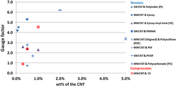
Figure 1. Gauge factors of the CNT/polymer nanocomposites under tension and compression as found in the literature [1–8].
Download figure:
Standard image High-resolution imageCurrently, several nanoscale mechanisms have been identified as contributors to the overall piezoresistive response of the CNT/polymer nanocomposites including (1) the electrical tunneling or electron hopping effect [17–25], (2) the inherent piezoresistive effect of the CNTs [24, 26–32], and (3) the CNT network effect [22, 24, 25]. Due to van der Waals forces, the CNTs tend to form bundles having large aspect ratios and, depending on the processing technique, these CNT bundles can form networks with specific mesoscale architectures, e.g. randomly dispersed or aligned. The mesoscale network of CNT bundles not only results in the nanocomposites being electrically percolated at extremely low weight percentages of the CNTs, but also plays a key role in determining the overall piezoresistivity of the nanocomposites when coupled with local electrical tunneling and inherent CNT piezoresistive effects which originate at the nanoscale.
Efforts to model the piezoresistive response of nanocomposites have included resistor network models [22, 24, 25] and micromechanics models [33–35] based on finite element analysis (FEA). The advantage of the resistor network model is that it can capture the randomness of the CNTs in a more direct sense by modeling the CNTs as rectangles or cylinders that are randomly dispersed in the 2D or 3D unit cell. The disadvantage of this modeling approach is that it does not precisely obtain the local kinematics and electrostatics of the CNT and the polymer matrix within the network which are crucial for modeling the piezoresistive response of the nanocomposites. On the other hand, although the micromechanics models based on FEA can more precisely obtain the kinematics and electrostatics of the local nanocomposite representative volume elements (RVEs), due to computational challenges in terms of meshing and large degrees of freedom, these models have only been focused on the local transverse and axial tip-to-tip piezoresistive responses of the CNT bundles [33–35]. Without the 3D network effect, the micromechanics models have not been able to directly capture how the electrical percolation and the piezoresistive responses of the nanocomposites can occur at such low CNT weight percentages and why the measured gauge factors can vary significantly in experiments.
In this paper, to model the piezoresistive response of the macroscale nanocomposite specimen and to address the multiscale nature of the problem, a 3D computational multiscale piezoresistive model is developed. In this model, idealized 3D cubic mesoscale RVEs and a 3D hexagonal nanoscale RVE are used to obtain the coupled electromechanical properties representing the macroscale nanocomposite and nanoscale effective bundles, respectively. The nanoscale RVEs are critical to directly capture the electrical tunneling and inherent CNT piezoresistivity effects while the mesoscale RVEs provide insight on the sensitivity of the macroscale response to the mesoscale network features such as longer range dispersion, alignment and bundle aspect ratio. The multiscale approach employs a concurrent coupling of scales wherein effective properties are first passed up from the nanoscale and are then used to start a top-down/bottom-up iterative incremental loading process during which global state variables are passed to the finer scale and updated effective properties are passed up to the coarser scale. The concurrent multiscale model accounts for the interactions between the CNT bundles through the local effective properties as against direct bundle interactions studies using CNT network models. By studying a range of meso and nanoscale dispersions of CNTs, the multiscale modeling approach is able to provide a qualitative understanding of the multiscale effects driving the macroscale gauge factors observed in experiments. This is achieved by studying several mesoscale CNT bundle distribution and orientation cases to establish the bounds for the observed gauge factors and to provide an assessment of the governing mechanisms behind the observed piezoresistivity.
2. Model description
2.1. Mesoscale dispersion scenarios for 3D computational multiscale model
The macroscale boundary value problem selected for the present work consists of a nanocomposite dogbone specimen with electrodes for monitoring the macroscale piezoresistive response (figure 2(a)). The configuration corresponds to a uniform state of strain and electric field at the macroscale applied on a representative cube of nanocomposite mesoscale RVE with an edge length of 1 mm, as seen in figure 2(b). The mesoscale RVE is meshed by eight-node linear hexahedron elements. For each element, there are eight subelements encompassing the eight gaussian integration points, as seen in figure 2(c). Within each element of figure 2(b), it is assumed that the material is either pure polymer matrix or polymer nanocomposites reinforced by CNT bundles, which can be aligned in any orientation within each subelement, as seen in figure 2(d). To simplify the problem, it is further assumed that the individual CNTs within the bundle are arranged in a hexagonal packing, locally aligned, with different cases of infinite or finite aspect ratios ( ), for which the hexagonal nanoscale RVE [36], as shown in figure 2(e), is used. Although the CNT orientation and weight (or volume) fractions of the local nanoscale RVE are not necessarily the same for the subelements in figure 2(c), the global weight fractions of CNTs within the mesoscale RVE is fixed, while different mesoscale dispersions are considered.
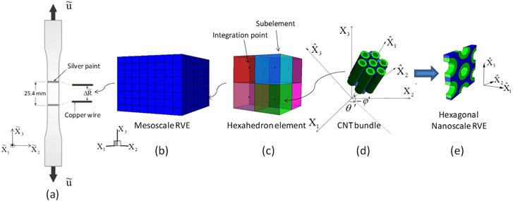
Figure 2. Schematics of the 3D computational multiscale micromechanics model for the nanocomposite specimen under uniaxial strains. (a) The macroscale nanocomposite specimen under uniaxial strains. (b) The mesoscale RVE (1 mm3) for the nanocomposite material within the specimen. Note that in real computations the number of elements used is 8 000, i.e. 64 000 subelements. (c) One single hexahedron element within the mesoscale RVE. (d) Illustration of the CNT bundle within the subelement. (e) The nanoscale RVE representing the CNT bundle. Note that  on the coordinate system denotes the macroscale whereas the
  denotes the nanoscale, with the mesoscale denoted with an unmodified Xi coordinate system.
Download figure:
Standard image High-resolution imageIn order to classify and correlate some of the range of possibilities for mesoscale CNT bundle dispersion scenarios, a diagram of idealized mesoscale CNT bundle dispersions at fixed global weight percent is provided in figure 3. The diagram is constructed based on three axes which represent the three dispersion factors considered: (1) the CNT mesoscale subcell dispersions, (2) the local CNT orientations within the subcell, and (3) the local CNT volume fraction within the subcell. In traveling from left to right along microstructure subcell distribution axis, the dispersion of the CNT occupied cells is transitioned from the extreme of statistically well-dispersed, to the intermediate of partially columned, to fully columned, and to the other extreme of fully locally agglomerated. In moving from the bottom up in the subcell orientation axis, the local orientations of the CNTs within the subcell are transitioned from the extreme of vertically aligned to the intermediate of randomly aligned, and further to another extreme of transversely aligned. Finally, in moving from back to front along the local volume fraction axis, the distribution of local subcell volume fractions of the CNTs is transitioned from the extreme of all CNTs concentrated in a single subcell (i.e. the maximum local subcell volume fraction with all other subcells being pure matrix) to a small number of subcells having a lower local subcell volume fraction, to several subcells having a mixture of lower local subcell volume fraction. Finally, we get to the other extreme of all subcells having an equal and still lower local subcell volume fraction which is therefore equal to the global CNT volume fraction of the nanocomposite. Each of the subcells presented in figure 3 is equivalent to an element in the mesoscale RVE shown in figure 2(b).
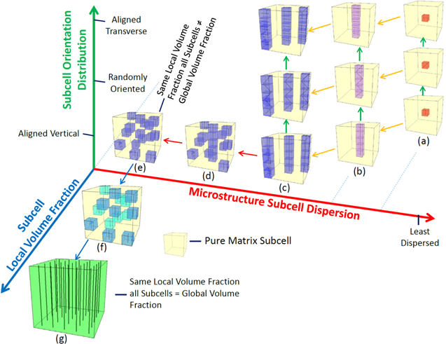
Figure 3. The diagram of mesoscale CNT dispersions for the 3D multiscale model. It is to be noted that each of the subcells presented here is equivalent to an element in the mesoscale RVE shown in figure 2(b).
Download figure:
Standard image High-resolution imageOne potential path relating the extreme cases is (a)–(g) in figure 3. The path begins with the fully agglomerated, vertically aligned dispersion in (a), transitions to single and multiple aligned columns in (b) and (c), respectively, disperses the multiple columns into partially and fully randomly dispersed subcells in (d) and (e), respectively, and finally begins dispersing the CNTs into more subcells in (f), until all subcells have the same local volume fraction of aligned CNTs, i.e. the fully dispersed case in (g). Although such idealized mesoscale dispersions do not directly correspond to the experimentally observed dispersions, they do resonate with experimental efforts to control CNT dispersion. For example, several authors [6, 37, 38] have employed dielectrophoresis as means to take initially well-dispersed and randomly oriented CNTs (i.e. moving up the orientation axis from (g) in figure 3) to a mostly aligned filament structure of CNTs which might be represented somewhere in the vicinity slightly above and between cases (d) and (e) with the CNTs mostly aligned and mostly in columns. Thus, understanding the difference in gauge factors between different subcell orientation cases of (d) and (e) can aid in obtaining a qualitative appreciation for the advantages of aligning CNTs, and perhaps point towards preferred dispersions for obtaining tailored gauge factor values. While the diagram in figure 3 is intended to show a spectrum of CNT dispersion possibilities for the 3D multiscale model, here we focus on only a few cases in an effort to demonstrate the sensitivity of the observed gauge factors to the meso and nanoscale dispersions and model parameters.
2.2. Computational procedures for the 3D multiscale model
The computations are conducted using an in-house multiscale finite element code which follows similar procedures as those discussed in detail in [39] and are briefly summarized here. It is assumed that the mechanical properties of the CNT and the polymer matrix are linear elastic under small strain assumptions. In order to initialize the local mechanical properties for the mesoscale RVE, the nanoscale effective stiffness tensor  of the local nanocomposites reinforced by CNT bundles is obtained from the computational micromechanics method by solving several periodic boundary value problems on the hexagonal nanoscale RVE5
[36]. The nanoscale effective stiffness is then substituted into the integration points of the mesoscale RVE using coordinate transformations [39] between the local nanoscale and mesoscale coordinate systems. By applying the computational micromechanics method again, i.e. solving the same periodic boundary conditions on the mesoscale RVE, the effective mechanical stiffness tensor Ceff of the mesoscale RVE is obtained. It is noted that in the absence of damage initiation and evolution as is assumed herein, these effective mechanical properties at the meso and nanoscales remain fixed throughout the remainder of the multiscale piezoresistive simulation. The local electrical properties, however, will evolve based on the nanoscale local electrical tunneling and inherent CNT piezoresistivity in response to applied strains.
of the local nanocomposites reinforced by CNT bundles is obtained from the computational micromechanics method by solving several periodic boundary value problems on the hexagonal nanoscale RVE5
[36]. The nanoscale effective stiffness is then substituted into the integration points of the mesoscale RVE using coordinate transformations [39] between the local nanoscale and mesoscale coordinate systems. By applying the computational micromechanics method again, i.e. solving the same periodic boundary conditions on the mesoscale RVE, the effective mechanical stiffness tensor Ceff of the mesoscale RVE is obtained. It is noted that in the absence of damage initiation and evolution as is assumed herein, these effective mechanical properties at the meso and nanoscales remain fixed throughout the remainder of the multiscale piezoresistive simulation. The local electrical properties, however, will evolve based on the nanoscale local electrical tunneling and inherent CNT piezoresistivity in response to applied strains.
Once the mechanical properties of the multiscale model are obtained following the bottom-up algorithm, incremental strains representative of uniform macroscale strain fields are applied on the mesoscale RVE to demonstrate the multiscale piezoresistive response using a top-down/bottom-up algorithm. The top-down portion of the algorithm begins with the homogeneous macroscale strain field increment  of the specimen being applied to the mesoscale RVE as periodic boundary conditions, as a result of which the mesoscale strain tensor
  at every integration point of the mesoscale RVE is obtained. These mesoscale strains are then applied to the nanoscale RVEs as periodic boundary conditions by coordinate transformation such that the local kinematics of the nanoscale RVEs at the various subelement locations throughout the mesoscale RVE can be obtained. The electrical tunneling algorithm within the finite element domain of the nanoscale RVEs has been discussed in detail in [34]. Applying this algorithm to all matrix integration points in the well-dispersed hexagonal nanoscale RVEs leads to electrical tunneling pathways within the matrix for percolated weight concentrations [34, 39]. The shape and local resistivity of these tunneling paths are dependent on the relative locations of the CNTs within the hexagonal nanoscale RVE and therefore are evolving in accordance with the local mesoscale strain applied at the boundary of the nanoscale RVE. The CNTs within the nanoscale RVEs are also expected to exhibit inherent piezoresistivity such that the change in resistivity of the CNT is related to the strain in the CNT through the piezoresistive strain coefficients as [33],

Though there have been many efforts reported which have employed either modeling or experimental techniques to assess the inherent piezoresistive response of the CNTs when subjected to applied deformation in the CNT axial direction [24, 26–32], the complete set of coefficients for the CNT inherent piezoresistive strain tensor are yet to be obtained. In the current study, based on the expected diagonal nature of the CNT resistivity and the similarity of the axial and hoop directions of the CNT corresponding to the rolled graphene sheet, it is assumed that  with all other
  being zero. This assumption allows for the identification of the distinct contributions to the inherent piezoresistive response of what are expected to be the largest strain contributions, though if identified from experiments or atomistic/quantum simulations, cross coupling (e.g.
  ) and shear effects (e.g.
  or
or  ) could readily be introduced to the model without loss of generality.
Once the distribution of resistivities within the nanoscale RVEs is obtained, the effective electrical properties are obtained at each scale following again a bottom-up algorithm. The electrical energy equivalence method [33] is used to obtain the effective electrostatic properties  of the nanoscale RVE. For the cases with finite aspect ratio of CNTs, it is noted that the end to end electron hopping between CNT bundles is rare given that the end to end distances are typically larger than electrical tunneling range (1–5 nm). It has been shown that even in the presence of tip to tip electron hopping, the electric fields and current density are uniform away from the tip [34]. Thus, only the end effects related to transition between the CNT and polymer medium at the ends is considered in this work. In the current work, the axial electrical conductivity for the finite aspect ratio CNTs is then evaluated by modifying the axial resistivities obtained from the nanoscale RVEs using energy equivalence in order to account for the end effects. The axial effective resistivities are modified using a composite cylinder model accounting for the polymer medium at the ends using the procedure discussed in [41, 42]6
. The geometries of the axisymmetric model are chosen to be LCNT/
of the nanoscale RVE. For the cases with finite aspect ratio of CNTs, it is noted that the end to end electron hopping between CNT bundles is rare given that the end to end distances are typically larger than electrical tunneling range (1–5 nm). It has been shown that even in the presence of tip to tip electron hopping, the electric fields and current density are uniform away from the tip [34]. Thus, only the end effects related to transition between the CNT and polymer medium at the ends is considered in this work. In the current work, the axial electrical conductivity for the finite aspect ratio CNTs is then evaluated by modifying the axial resistivities obtained from the nanoscale RVEs using energy equivalence in order to account for the end effects. The axial effective resistivities are modified using a composite cylinder model accounting for the polymer medium at the ends using the procedure discussed in [41, 42]6
. The geometries of the axisymmetric model are chosen to be LCNT/ and
and  /
/ , where
  is the length of CNTs,
  is the radius of the CNTs and
  is the edge length of the axisymmetric RVE, such that
  increases from
  to
to 
 . The axial resistivities, however, are only evaluated once in the unstrained state and modified for the finite aspect ratios assuming that for small applied strains, the CNT governed axial conductivity does not undergo a significant variation.
Once the effective electrostatic properties  of the nanoscale RVE are obtained, they are then substituted into the integration points of the mesoscale RVE by coordinate transformation to represent the effective electrostatic properties of the mesoscale subelements. The electrical energy equivalence method is then used again to obtain the effective electrostatic properties
  of the mesoscale, which, given the uniform macroscale electric field, are taken to be representative of the macroscale effective properties of the nanocomposite. Similar top-down/bottom-up procedure is followed in applying homogeneous macroscale strain increments (
 ) as displacement boundary conditions on the mesoscale RVE, up to a maximum macroscale applied strain of
  , while obtaining the effective mesoscale resistivity,
  , of the mesoscale RVE. Under the applied macroscale strain field, correlation between the mechanical and electrostatic properties (i.e. piezoresistivity) of the macroscale nanocomposites can then be obtained and quantified as the macroscale effective gauge factor defined as [33]:
It is noted that the ratio  can be directly attributed to the nanoscale piezoresistive mechanisms of the material, i.e. the electrical tunneling effect and inherent piezoresistivity of the CNT, and that in absence of these nanoscale effects the ratio becomes 1 meaning that the piezoresistive response is only dependent on geometric effects [43] associated with the Poisson's ratio as it is in the metal wires of typical strain gauges.
3. Results and discussion
The modeling work is focused on the piezoresistive response of macroscale nanocomposite under small uniaxial tension or compression tests ( ). To be consistent with experiments, the study is focused on the MWCNT/vinyl ester (VE) nanocomposites with 1.0%wt of the CNTs [8]. The weight concentrations were converted to volume fractions based on the densities of the CNT (1.4
  ) and the polymer (1.17
  [44]). The outer and inner diameters of MWCNTs are fixed at 13 and 4 nm, respectively [45]. The Young's modulus and Poisson's ratio of the CNT are taken to be 1.1 TPa and 0.14 [46]. The Young's modulus of VE is 3.60 GPa [44], and the Poisson's ratios of VE is chosen to be 0.3. The initial isotropic resistivity within the CNT annulus is chosen to be
 [42, 47], and VE is likewise isotropic with resistivity of 1015
  in the absence of electrical tunneling, which is within the typical range of values commonly reported for insulating polymers in experiments. For the electrical tunneling effect within the polymer matrix, an average barrier height of λ = 1.5 eV [25] is considered for VE. In some studies [24, 48] inherent CNT piezoresistive gauge factors are reported to be
  7 under small strains, while in contrast, Stampfer et al [31] reported CNT inherent piezoresistive gauge factor can be as large as 2900. In this study a CNT inherent gauge factor of 10 will be converted into diagonal isotropic piezoresistive coefficients
  [33] to study its influence on the overall piezoresistive response of the CNT/polymer nanocomposites.
3.1. The first CNT dispersion scenario (S1)
The first CNT dispersion scenario (S1) is the ideal dispersion case wherein the CNT subcells are statistically well-dispersed such that for every subcell the CNT local volume fraction is equal to the global volume fraction of the nanocomposites. For this scenario, the vertical, random, and transverse orientation cases are considered corresponding to those moving up the orientation axis from (g) in figure 3. The resistivity distribution for the meso and nanoscale RVEs for this scenario are provided in figures 4(a) and (b), respectively. It is noted that with ideal dispersion, every subelement of the mesoscale contains CNTs, i.e. there are no pure polymer subelements, and as such, every subelement of the mesoscale RVE has a corresponding nanoscale RVE to represent the local nanoscale response. Further, as the local nanoscale weight percentage of the hexagonally packed CNTs equals to the global weight percentage, which is chosen to be 1.0%wt, the CNT separation distances at the nanoscale (110.8 nm) are far greater than the maximum hopping range (3.59 nm [34]) for the hopping barrier considered herein (1.5 eV). Thus, there are no electrical tunneling conductive paths between the CNTs in figure 4(b) and only the inherent CNT piezoresistivity mechanism is active for cases in scenario 17 .
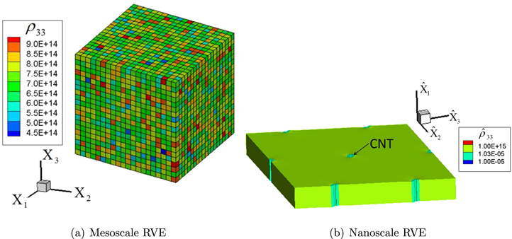
Figure 4. The 3D multiscale model for scenario 1 (S1) with infinitely long CNTs. (a) Illustration of the mesoscale RVE with well-dispersed, randomly oriented, and 1.0%wt nanoscale RVEs. (b) Illustration of the 1.0%wt nanoscale RVE under the transformed mesoscale strain field of  , in which R can be found in [39] (displacement magnification factor: 37).
Download figure:
Standard image High-resolution imageThree different cases of CNT distribution within the subelements is studied for the first dispersion scenario viz. (a) vertically aligned case where all CNTs are oriented in the  direction (case S1V), (b) transverse plane alignment case where the CNTs are randomly oriented in the
  plane (case S1R2) and (c) the random orientation case where the CNTs are oriented randomly in the 3D space (case S1R3). For each of these cases, both infinitely long and finite aspect ratio of CNTs are considered8
. Following the bottom-up algorithm, the mesoscale RVE's effective mechanical properties for each of the orientation cases are obtained and are summarized in table 1 with infinitely long CNTs. The mechanical properties of the pure polymer matrix are also listed in table 1 for comparison purposes. It is observed that, in agreement with the CNT dispersion symmetries, the nanocomposites with vertically aligned (S1V) and transverse plane CNTs (S1R2) both yield transversely isotropic effective mechanical properties, with the axis of symmetries in
plane (case S1R2) and (c) the random orientation case where the CNTs are oriented randomly in the 3D space (case S1R3). For each of these cases, both infinitely long and finite aspect ratio of CNTs are considered8
. Following the bottom-up algorithm, the mesoscale RVE's effective mechanical properties for each of the orientation cases are obtained and are summarized in table 1 with infinitely long CNTs. The mechanical properties of the pure polymer matrix are also listed in table 1 for comparison purposes. It is observed that, in agreement with the CNT dispersion symmetries, the nanocomposites with vertically aligned (S1V) and transverse plane CNTs (S1R2) both yield transversely isotropic effective mechanical properties, with the axis of symmetries in  direction. In contrast, the nanocomposites with randomly oriented CNTs (S1R3) yield isotropic effective mechanical properties. In addition, the mechanical properties for the nanocomposites is observed to be larger especially in the directions corresponding to local CNT alignment directions. For example, compared to the pure polymer matrix, the nanocomposite with vertically aligned CNTs (S1V) have a 228% increase in the effective Young's modulus of
  . In contrast, while
  of nanocomposite with transverse plane CNTs (S1R2) increased only by 14% relative to pure polymer because of CNT orientation in the transverse plane, the effective in-plane properties of
  and
and  increase by a much higher 57 and 71%, respectively. The increase in the in-plane elastic components for the transverse orientation case is large enough to make the transverse plane stiffer than the
  direction such that
  is larger for the S1R2 case as compared to S1V. Finally, for the nanocomposite with randomly oriented CNTs, the effective Young's modulus is only improved by 36% relative to the pure polymer. However, the improvement is in all the spatial directions because of the 3D random alignment of CNTs, and thus yields an
  larger than the transverse plane case as at least some of the CNTs are aligned in
  direction.
Table 1. The effective mechanical properties of the three mesoscale RVE cases for the first scenario (ideally well-dispersed) for the three different local CNT orientation cases studied herein. (Unit: GPa except for dimensionless Poisson's ratio.)
| Orientation |

|

|

|

|

|

|
| Vertical (S1V) | 11.82 | 0.298 | 1.408 | 1.403 | 3.501 | 3.889 |
| Transverse (S1R2) | 4.098 | 0.192 | 1.405 | 2.371 | 5.440 | 6.232 |
| Orientation |

|

|
— | — | — | — |
| Random (S1R3) | 4.910 | 0.289 | — | — | — | — |
| Pure polymer (VE) | 3.600 | 0.300 | — | — | — | — |
Having solved the mechanical problem by using the bottom-up algorithm, the macroscale strain field ( to ±1%,
  ,
,  ) is applied to the cubic mesoscale RVE in 10 equally increased load steps, and with the mesoscale strain at each step passed down to the subelement nanoscale RVEs using the top-down portion of the of the multiscale algorithm. As an illustration, the strain distribution of the mesoscale RVE with randomly oriented CNTs and under the macroscale field of (
 ,
,  ,
,  ) is shown in figure 5. The mesoscale strain field at every integration point of the mesoscale RVE is rotated to the local nanoscale coordinates and applied to the nanoscale RVE, such that the strains in the CNTs and the distances between them are obtained and used to update the electrical resistivities within the nanoscale RVE. The resistivity distribution of the nanoscale RVE at an integration point of the mesoscale RVE and under the macroscale strain field of
  ,
,  ,
,  is shown in figure 4(b). It is observed that the local resistivities of the polymer medium do not change with applied strains in absence of electrical tunneling mechanism because of large intertube distances. However, the inherent CNT piezoresistivity leads to a distribution of local resistivities within the CNTs. Following the bottom-up portion of the algorithm at each load step, the effective resistivities
  of the nanoscale RVE are obtained by using the energy equivalence method, and are rotated back into the mesoscale coordinate system to represent the integration point of the mesoscale RVE (figure 4(a)). Finally, the energy equivalence method is used again to obtain the effective resistivities
  of the mesoscale RVE, which are used to represent the macroscale, such that
  . Therefore the correlation (piezoresistivity) between the applied macroscale strain field
  and the macroscale effective resistivities
  of CNT/polymer nanocomposites is obtained allowing for the calculation of the gauge factor according to equation (2).
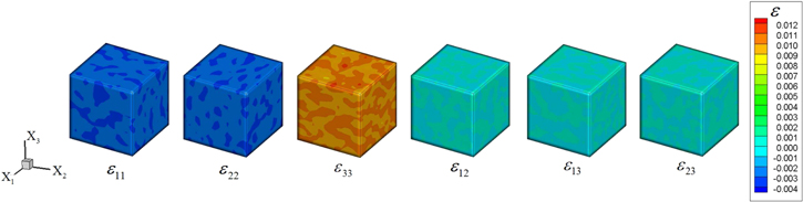
Figure 5. Strain distribution of the mesoscale RVE under the macroscale strain field of ( ,
,  ,
,  ). Within the mesoscale RVE there are hexagonally packed and randomly oriented 1.0%wt infinitely long CNTs in each subelement.
Download figure:
Standard image High-resolution imageFor the mesoscale RVE with infinitely long CNTs, the relative change of effective resistivity  of the mesoscale RVE with the change of macroscale strain
  is shown in figure 6 for each of the orientation cases. The zero-strain effective resistivities
  , with the tensile and compressive effective gauge factors (
 and
and  ) of the mesoscale RVE for different CNT orientation cases are summarized in table 2. The effective gauge factors,
  and
and  , are calculated using equation (2) where the effective Poisson's ratio components are calculated during the initial bottom-up portion of the multiscale algorithm. From table 2 it can be seen that the nanocomposites with vertically aligned infinitely long CNTs have the lowest zero-strain effective resistivity of
 because the infinitely long CNTs result in electrical percolation in the
  direction. Thus, for the vertically aligned CNTs, the effective resistivity is expected to be close to the rule of mixtures solution, i.e. CNT bundle dominated. Moreover, the effective gauge factor for the infinitely long vertically aligned CNTs is observed to be 10, i.e. equal to the inherent CNT gauge factor, because the vertically aligned CNTs span the entire length of the nanoscale RVE resulting in perfect transfer of the applied strains to the CNTs. For the transversely oriented and randomly oriented CNT cases, only a small fraction of the applied strains gets transferred to the CNTs, resulting in smaller gauge factors (figure 6) as the inherent CNT piezoresistivity is the only active piezoresistive mechanism. The transversely oriented (S1R2) case has all of the infinite long CNTs dispersed in
  plane such that the material does not get electrically percolated by the CNTs in
  direction, instead it demonstrates nearly the same level of electrically insulating response as the pure polymer matrix (
 =
= 
 ). In this case, the inherent piezoresistivity of the CNT can not be transferred to the mesoscale and the effective gauge factors are dominated by the geometric effect9
resulting in a gauge factor of 1.4. It is to be noted that the geometric gauge factors mentioned herein for the polymer matrix and the S1R2 case (which are electrically insulating in the
). In this case, the inherent piezoresistivity of the CNT can not be transferred to the mesoscale and the effective gauge factors are dominated by the geometric effect9
resulting in a gauge factor of 1.4. It is to be noted that the geometric gauge factors mentioned herein for the polymer matrix and the S1R2 case (which are electrically insulating in the  direction) are very difficult to be observed experimentally. This is because the resistivities larger than 1010
  are extremely difficult to measure and thus any associated change in the resistivity leading to effective gauge factors may not be experimentally observed. This will hold true for other cases throughout the manuscript with unstrained effective resistivities larger than 1010
  . The predictions based on the multiscale model presented herein, however, are aimed at establishing bounds for effective properties and understanding the key features of the mesoscale morphology which affect the piezoresistive properties, and thus, the modeling predictions are of interest for the current work.

Figure 6. The relative change of effective resistivity  of the mesoscale RVE with infinitely long CNTs when the macroscale strain
  is varied from 0 to ±1%.
Download figure:
Standard image High-resolution imageTable 2.
The zero-strain resistivities  (unit:
  ), tensile gauge factors
  , and compressive gauge factors
  of the mesoscale RVE with infinitely long and finite aspect ratio CNTs for scenario 1. Note that the gauge factors are computed at
  .
.
| Infinitely long CNTs | Finite aspect ratio CNTs | |||||
| Orientation |

|

|

|

|

|

|
| Vertical (S1V) |

|
10 | 10 |

|
1.6 | 1.6 |
| Transverse (S1R2) |

|
1.4 | 1.4 |

|
1.4 | 1.4 |
| Random (S1R3) |

|
5.4 | 5.4 |

|
1.6 | 1.6 |
| Pure polymer |

|
1.6 | 1.6 |

|
1.6 | 1.6 |
For the nanocomposites with infinitely long random CNTs, the material is partially percolated in all directions such that in each direction there are a few conductive paths formed by the randomly oriented network, i.e. the probability of a direction being disrupted by vertical/transverse orientation of neighboring subelements is near zero for the well-dispersed scenario considered here. As such, the randomly oriented case yields effective mesoscale resistivities and gauge factors which are between the vertically aligned and transversely oriented cases. From figure 6 and table 2 it is further observed that the relative change of effective resistivity  and gauge factors of the mesoscale RVE exhibit symmetric piezoresistive response and same gauge factors in tension and compression, as against tension/compression asymmetry observed in some experimental studies in the literature [49, 50], for any of the CNT orientation cases. This is because (1) the inherent piezoresistivity of the CNT is assumed to be linear and tension/compression symmetric with the applied strains on the CNT [33], (2) under small macroscale tension and compression, the strains on the CNTs within the mesoscale RVE are also linear and tension/compression symmetric, and (3) under small macroscale strains the mesoscale RVE's geometric effect itself has good tension/compression symmetry.
As a comparison, for the mesoscale RVE with finite aspect ratio CNTs, the zero-strain effective resistivities  and tensile and compressive effective gauge factors (
 and
and  ) of the mesoscale RVE for different CNT orientation cases are summarized in table 2 alongside the infinitely long CNT cases. It can be seen that the nanocomposites with vertically aligned, randomly oriented, and transversely oriented finite aspect ratio CNTs have zero strain resistivities on the order of 1013–1014
  , which are highly electrically insulating. Thus, the gauge factors for each of the orientation cases are those obtained entirely from the geometric effect as relative change in effective resistivity with applied strains is approximately close to zero. This is because as the CNTs are of finite aspect ratios, there is a smaller chance of a strong percolating conductive paths formed within the material for any CNT orientations.
From the results presented herein, it is observed that as long as the material is electrically percolated by the CNTs themselves, the inherent piezoresistivity of the CNT has a significant influence on the macroscale piezoresistivity of the CNT/polymer nanocomposites because the applied strains get transferred to the CNTs better. However, real CNTs are of finite lengths/aspect ratios and it is very difficult to achieve the ideal dispersion of mesoscale subcells as considered in scenario 1. In addition, the CNTs tend to form bundles because of van der Waals forces and the local volume fraction of the CNTs is expected to be much higher. Given that the experimentally observed gauge factors are larger than just the geometric response, it is expected that the effective piezoresistive response is governed by additional piezoresistive mechanisms e.g. nanoscale electrical tunneling. For the dispersion scenario considered for scenario 1, the electrical tunneling was absent because of large intertube distances. Therefore, additional CNT dispersion scenarios are considered herein to better represent the CNT morphology in experimental nanocomposite samples allowing for the other piezoresistive mechanisms, e.g. electrical tunneling, to be activated, and therefore to achieve CNT/polymer nanocomposites with piezoresistive response larger than the pure geometric effect.
3.2. The second (S2) and third (S3) CNT dispersion scenarios
In most CNT/polymer nanocomposites, it is expected that the CNTs are more likely to be a mixture of well-dispersed and locally agglomerated CNTs (due to van der Waals forces) randomly distributed throughout the matrix as opposed to the ideal dispersion discussed in scenario 1. To capture the CNT agglomeration effect the second (S2) and third (S3) CNT dispersion scenarios are studied, which correspond to randomly oriented subcell versions of (e) and (d), respectively, in the dispersion map of figure 3. For the second scenario, the agglomerated CNT subcells have local CNT volume fractions which are much higher than the global volume fraction of the nanocomposite (e.g., nearly 60% locally compared to the 1% global) and are statistically well-dispersed (randomly distributed) throughout the mesoscale RVE, with the non-agglomerated subcells consisting of pure matrix. For the third scenario, the agglomerated CNT subcells are partially well-dispersed and partially columned, with the columns representing the mesoscale conductive paths formed by the CNTs.
The nanoscale RVE for scenario 2 is chosen to have 62.5%vol of the CNT as shown in figure 7(a). As the CNT separation distances (2.66 nm) in the nanoscale RVE are within the electrical tunneling range (3.59 nm) for the height of barrier considered herein (1.5 eV), the electrical tunneling effect is engaged (i.e. the nanoscale RVE demonstrates electrical tunneling induced percolation in the transverse direction) along with the inherent piezoresistivity of the CNTs. Electrical tunneling paths (figure 7(a)) are formed among the CNTs, and are evolving with the applied strain field along with the inherent piezoresistivity of the CNT. The mesoscale RVE for scenario 2 is illustrated in figure 7(b). It can be seen that the elements containing the nanoscale RVE are well-dispersed within the mesoscale RVE with CNTs randomly oriented in 3D space (case S2R3) for each of the subelements. The nanoscale RVE for scenario 3 is chosen to be the same as in scenario 2, however, it can be seen from mesoscale RVE for scenario 3 as illustrated in figure 7(c) that mesoscale elements containing the randomly oriented nanoscale RVE subelements are partially well-dispersed and partially columned. In the subsequent computations, the total 106 elements containing the nanoscale RVE are stacked into either three (case S3C3R3) or five (case S3C5R3) columns, with the remaining elements randomly dispersed into the remaining mesoscale domain.

Figure 7. The 3D multiscale model for scenarios 2 and 3. (a) Illustration of the 62.5%vol nanoscale RVE under the transformed mesoscale strain of  (displacement magnification factor: 68). (b) Illustration of the 1%wt mesoscale RVE with well-dispersed, randomly oriented (S2R3) infinitely long CNTs with 62.5%vol nanoscale volume fraction for scenario 2. (c) Illustration of the 1%wt mesoscale RVE with partially dispersed and partially columned, randomly oriented (S3C3R3 or S3C5R3), and 62.5%vol nanoscale RVEs for scenario 3.
Download figure:
Standard image High-resolution imageFollowing the initial bottom-up portion of the multiscale algorithm, the effective mechanical properties of the mesoscale RVE for scenarios 2 and 3 are first obtained. For demonstration purposes, the effective mechanical properties with randomly oriented nanoscale RVE (S2R3, S3C3R3 and S3C5R3) are summarized in table 3. The mechanical properties of the pure polymer matrix are also listed in table 3 for comparison purposes. It is to be noted that for scenarios 2 and 3, in which the local CNTs are agglomerated, the effective mechanical properties are very close to the pure polymer matrix. For example, the effective Young's modulus,  , is only improved by 4.4%, 11% and 14% for the cases of S2, S3C3 and S3C5, respectively. Even though the local mechanical properties can be greatly improved due to CNT agglomeration, their influence on the macroscale effective mechanical properties is limited. In addition, the results in table 3 show that compared to the cases of S3 (3 columns) and S3 (5 columns), the S2 case shows larger increase in
  ,
,  ,
,  , while a smaller increase in
  . This is because while well-dispersed CNTs can help improve the overall mechanical properties in any directions, stacking of CNTs can help better improve the mechanical properties in the particular stacking direction of the CNTs.
Table 3. The effective mechanical properties of the mesoscale RVE for scenarios 2 and 3 (unit: GPa except for dimensionless Poisson's ratio). Note that the nanoscale RVE is randomly oriented for all of the 848 subelements within the 106 elements.
| Scenarios |

|

|

|

|

|

|
| S2 (S2R3) | 3.576 | 1.436 | 1.434 | 3.760 | 0.295 | 3.742 |
| S3 (3 columns) (S3C3R3) | 3.558 | 1.424 | 1.429 | 3.992 | 0.297 | 3.732 |
| S3 (5 columns) (S3C5R3) | 3.543 | 1.416 | 1.425 | 4.091 | 0.297 | 3.721 |
| Scenarios |

|

|
— | — | — | — |
| Pure polymer | 3.600 | 0.300 | — | — | — | — |
Having obtained effective mechanical properties at each scale, the macroscale strain field ( to ±1%,
  ,
,  ) is applied to the cubic mesoscale RVE in 10 equally increased load steps, and with the mesoscale strain at each step passed down to the subelement nanoscale RVEs using the top-down portion of the multiscale algorithm. First consider the mesoscale RVE with infinitely long CNTs in the local nanoscale RVEs. It has been shown that for 60% volume fraction, application of transverse strains on the nanoscale RVE results in strong piezoresistive response with nanoscale effective gauge factors of around 20 for 1% applied tensile/compressive strain [34]. However, for scenario 2, it is found that the nanoscale local piezoresistive response does not result in any change in the effective mesoscale piezoresistive response because of uniform dispersion of CNT occupying subcells i.e. with the change of macroscale strain
  , there is no10
relative change of effective resistivity
, there is no10
relative change of effective resistivity  of the mesoscale RVE. This is because for this dispersion scenario, as there are no percolating conductive paths formed within the mesoscale RVE, the local piezoresistive response of the infinitely long, locally agglomerated CNTs can not be transferred from the nanoscale to the mesoscale. The zero-strain effective resistivities,
  and the effective gauge factors (
 and
and  ), of the mesoscale RVE for scenario 2 with infinite long CNTs are summarized in table 4. It can be seen that as there are no percolating conductive paths, the zero-strain effective resistivities
  for vertical and transverse orientations are both
 , which are close to the insulating polymer matrix. The tensile and compressive gauge factors are 1.6, which is entirely from the geometric effect of the nanocomposites.
Table 4.
The zero-strain resistivities  (unit:
  ), tensile gauge factors
  , and compressive gauge factors
  of the mesoscale RVE for scenario 2 with infinitely long and finite aspect ratio CNTs. Note that the gauge factors are computed at
  .
.
| Infinitely long CNTs | Finite aspect ratio CNTs | |||||
| Orientation |

|

|

|

|

|

|
| Vertical (S2V) |

|
1.6 | 1.6 |

|
1.6 | 1.6 |
| Transverse (S2R2) |

|
1.6 | 1.6 |

|
1.6 | 1.6 |
| Random (S2R3) |

|
1.6 | 1.6 |

|
1.6 | 1.6 |
| Pure polymer |

|
1.6 | 1.6 |

|
1.6 | 1.6 |
For scenario 3 with infinitely long CNTs, the relative changes of effective resistivity  of the mesoscale RVE with the change of macroscale strain
  are shown in figure 8, with the zero-strain effective resistivities
  and tensile/compressive effective gauge factors (
 and
and  ) of the mesoscale RVE for different cases summarized in table 5. In addition to the randomly oriented CNTs (cases S3C3R3 and S3C5R3), local nanoscale orientations with all CNTs aligned in the
  direction (cases S3C3V and S3C5V) and with CNTs randomly oriented in the transverse
  plane (cases S3C3R2 and S3C5R2) are also studied in the current work. Figure 9 shows the orientations of nanotube bundles in the global mesoscale coordinate system for the three CNT orientation cases considered herein. For cases with random transverse orientation of CNTs (cases S3C3R2 and S3C5R2), it is observed from figure 9(a) that all of the CNTs in the nanoscale RVE remain perpendicular to mesoscale
  column orientation. Thus, the inherent CNT piezoresistivity in the CNT axial direction has a small effect on the effective piezoresistive response because the applied strains are transverse to the CNT alignment direction. Given that the CNTs are columned, the applied mesoscale strains get transferred as local transverse strains on the nanoscale RVEs leading to changes in the intertube distances. The transverse electrical tunneling pathways between the CNTs are very sensitive to transverse deformation which lead to changes in CNT intertube distances. Thus, the piezoresistive response is found to be governed by the electrical tunneling effect with asymmetric piezoresistive response in tension and compression yielding effective macroscale gauge factors of ∼155 and ∼80 for applied ±1% tensile and compressive strain, respectively. Thus, the effect of local nanoscale electrical tunneling gets significantly represented in the effective piezoresistive response of the nanocomposite.
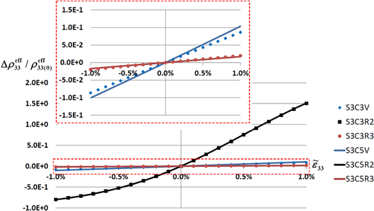
Figure 8. The relative change of effective resistivity  of the mesoscale RVE for scenario 3 with infinite long and finite aspect ratio CNTs when the macroscale strain
  is from 0 to ±1%. Note that the insets are the close-up plots for the vertical and random orientation curves.
Download figure:
Standard image High-resolution image
Figure 9. Illustration of the different combination of orientations of the nanoscale RVE within the columns of the mesoscale RVE. (a) Random orientation in the transverse  –
– plane. (b) Random orientation in the 3D space. (c) Vertical orientation in
  direction.
Download figure:
Standard image High-resolution imageTable 5.
The zero-strain resistivities  (unit:
  ), tensile gauge factors
  , and compressive gauge factors
  of the mesoscale RVE for scenario 3 with infinitely long CNTs. Note that the gauge factors are computed at
  .
.
| Infinitely long CNTs | Finite aspect ratio CNTs | |||||
| Orientation |

|

|

|

|

|

|
| 3 columns+vertical (S3C3V) |

|
10 | 10 |

|
1.6 | 1.6 |
| 5 columns+vertical (S3C5V) |

|
10 | 10 |

|
1.6 | 1.6 |
| 3 columns+transverse (S3C3R2) |

|
154 | 80 |

|
154 | 80 |
| 5 columns+transverse (S3C5R2) |

|
155 | 80 |

|
155 | 80 |
| 3 columns+random (S3C3R3) |

|
3.5 | 3.5 |

|
142 | 75 |
| 5 columns+random (S3C5R3) |

|
3.3 | 3.3 |

|
141 | 76 |
| Pure polymer |

|
1.6 | 1.6 |

|
1.6 | 1.6 |
In contrast, when the CNTs are oriented in the  direction as shown in figure 9(c) (cases S3C3V and S3C5V), the nanocomposite is more readily percolated in the
  direction because of the vertical columns and the infinite aspect ratio of the CNTs leading to effective nanocomposite resistivities closer to that of CNTs. For this case, the applied macroscale strains lead to smaller changes in the electrical tunneling pathways as electrical tunneling is less sensitive to axial deformations. However, the applied strains coincide with the axial direction of CNTs resulting in almost perfect strain transfer to the CNTs. This leads to the inherent CNT piezoresistivity dominating the effective piezoresistive response with observed effective gauge factor of 10 in both tension and compression, similar to the observation made for uniformly distributed vertically aligned subcells of scenario 1 (S1V). Finally, the CNT orientation of the randomly oriented CNTs (cases S3C3R3 and S3C5R3) is shown in figure 9(b) where both electrical tunneling and inherent piezoresistivity have some influence on the effective gauge factors because at least a fraction of CNTs are aligned or transverse to the direction of applied strains. However, with infinitely long CNTs the
  direction is already percolated in the unstrained state as is observed from the unstrained resistivities of order
  for both S3C3R3 and S3C5R3. Thus, the variations in local resistivities lead to only small changes in the effective resistivities which get reflected in effective gauge factors of ∼3.5 which are larger than the purely geometric response but much smaller than the electron hopping governed gauge factors of cases S3C3R2 and S3C5R2.
In addition to the infinitely long CNTs, scenarios 2 and 3 mesoscale RVEs were also studied using finite aspect ratio CNTs. For scenario 2 with CNTs of finite aspect ratio, the zero-strain effective resistivities  and tensile and compressive effective gauge factors (
 and
and  ) are summarized in table 4. It is observed that the zero-strain effective resistivities
  for vertical and transverse orientations are both
 , which are close to the insulating polymer matrix. As there are still no percolating conductive paths formed by the CNTs, with the change of macroscale strain
  , there is no relative change of effective resistivity
  of the mesoscale RVE for any orientations of the nanoscale RVE, and thus, the tensile and compressive gauge factors are 1.6, i.e. entirely from the geometric effect of the nanocomposites.
For scenario 3 with finite aspect ratio CNTs, the relative changes of effective resistivity  of the mesoscale RVE with the change of macroscale strain
  are shown in figure 10, with the zero-strain effective resistivities
  and tensile and compressive effective gauge factors (
 and
and  ) summarized in table 5. The unstrained resistivity for the transversely oriented CNT cases does not change for finite CNT aspect ratio, because the aspect ratio of CNTs affects the resistivity in the local axial CNT direction. Thus, the transverse local resistivity and the effective mesoscale resistivity do not undergo much change and are closer to the polymer matrix resistivity. However, the vertically aligned and randomly oriented CNT cases undergo large changes in unstrained resistivity such that with finite aspect ratios the effective resistivity is much higher than that for the infinitely long CNTs. For these cases, the axial CNT resistivity has a significant effect on the effective mesoscale resistivity. In addition, it is found that similar to cases S3C3R2 and S3C5R2 with infinite long CNTs, when the finite aspect ratio CNTs are randomly oriented in the transverse
  –
– plane, the nanoscale CNT tunneling paths have a significant effect on the mesoscale percolating conductive paths, with the local nanoscale electrical tunneling effect and its sensitivity to applied strains significantly contributing to the mesoscale piezoresistive response yielding large magnitude for effective gauge factors, i.e. ∼155 and ∼80 in tension and compression, respectively. In contrast, when the nanoscale RVEs are vertically aligned in
  direction (cases S3C3R3 and S3C5R3), as the CNTs are of finite aspect ratios, there are no electrical tunneling paths within the mesoscale RVE and the overall piezoresistivity therefore reflects only the geometric effect and yields an effective gauge factor of 1.6. For the randomly oriented cases (i.e. cases S3C3R3 and S3C5R3) as illustrated in figure 9(b), the piezoresistive response of the mesoscale RVE can be varying in a large range depending on the specific orientation configurations within the conducting columns, as shown in figure 10. In general, the specific orientation distribution of CNTs, specially in the vertical columns, will govern if the
  direction gets electrically percolated even for finite aspect ratio of CNTs. For the current work, the
  direction does not get electrically percolated, unlike the infinitely long CNT case, as observed from the unstrained effective resistivities of order 1012 (table 4). Thus, the evolution of electrical tunneling based local resistivities has a significantly larger effect on the gauge factors resulting in gauge factors of ∼140 and ∼75 in tension and compression, respectively.
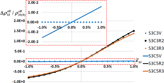
Figure 10. The relative change of effective resistivity  of the mesoscale RVE for scenario 3 with finite aspect ratio CNTs when the macroscale strain
  is from 0 to ±1%. Note that the random orientation curves can vary in a large range depending on specific orientation combinations of the elements with nanoscale RVE.
Download figure:
Standard image High-resolution imageIt is further observed from tables 4 and 5, for infinitely long and finite aspect ratio CNTs, that the mesoscale RVE with 3 columns and 5 columns both yield nearly the same piezoresistive gauge factors. This implies that although the number of percolating conductive paths can influence the magnitude of effective resistivity of the CNT/polymer nanocomposites, the piezoresistive response of the material is primarily governed by the nanoscale electrical tunneling effect and the number of conductive paths have a smaller influence. Furthermore, it is observed from figures 9 and 10 that the piezoresistive response of the mesoscale RVE exhibits tension/compression asymmetry for both infinitely long and finite aspect ratio CNTs, with the piezoresistive response larger in tension than in compression. The asymmetric response further indicates that electrical tunneling is the primary governing mechanism for the effective piezoresistive response. Thus, the tensile gauge factors  at
at  are larger than compressive gauge factors
  at
at  . The governing equation of the electrical tunneling effect [34] is found to have strong tension/compression asymmetry such that the magnitude of relative change of resistivity are different in tension and compression. Therefore, the overall piezoresistive response of the CNT/polymer nanocomposites is reflective of the nanoscale electrical tunneling effect and shows tension/compression asymmetry.
3.3. Discussion
The results presented in the current work study some of the specific cases of mesoscale CNT dispersion scenarios in order to explore the key features of CNT/polymer nanocomposite piezoresistive response and establish a bound on the observed effective properties.The results from the multiscale model presented herein predict that for different mesoscale dispersion scenarios the effective piezoresistive response can be significantly different. It is predicted that for the uniformly dispersed mesoscale CNT scenario, the electrical tunneling mechanism is absent because of large intertube distances. Thus, the effective gauge factors are entirely governed by the nanoscale inherent CNT piezoresistivity. However, experimentally fabricated nanocomposite samples are not likely to have uniform mesoscale CNT subcell dispersion. Thus, non-uniform agglomerated mesoscale dispersion cases with larger local volume fractions were studied to better represent experimental nanocomposite samples.
In contrast to uniform subcell dispersion cases, for the agglomerated mesoscale CNT dispersion scenario, the local volume fraction of the CNTs can be large enough to allow for electrical tunneling between the CNTs. For these cases, the effective gauge factors are affected by both nanoscale electrical tunneling and inherent CNT piezoresistivity with the electrical tunneling being the dominant phenomenon. However, the effective piezoresistive response is significantly affected by the dispersion of CNT occupying subcells at the mesoscale and the local orientations of the CNTs. This is specially evidenced by the large range of effective gauge factors predicted here i.e. from a minimum of around 1.5 from purely geometric effects to a maximum of order 102 when the electrical tunneling effect gets significantly represented in the effective piezoresistive response. Although, the mesoscale dispersion cases studied herein do not exactly represent the experimentally fabricated nanocomposite samples, they do span the range of possibilities of the nanoscale and mesoscale microstructural features. Thus, the effective gauge factors obtained in the current work provide the bounds for the piezoresistive properties obtained in the literature as presented in figure 1. It is further noted that the current work incorporates the transverse electrical tunneling between the CNTs, however perpendicular/oblique angle and overlapping CNT junctions [20, 51], as illustrated in figure 11 are not represented in the current work because of the idealized hexagonally packed nanoscale RVE. In order to study these effects, a detailed understanding of meso and nanoscale microstructure from scanning electron microscopy and transmission electron microscopy is required to create the meso and nanoscale RVEs. It is anticipated that incorporating such effects could further provide a more quantitative assessment of the effective gauge factors in addition to the qualitative effects of meso and nanoscale dispersions studied herein.
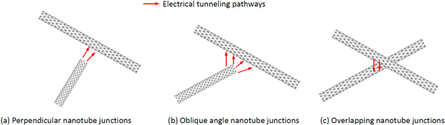
Figure 11. Illustration of CNT electrical tunneling junction types not considered in the current multiscale model. (a) Perpendicular nanotube junctions (b) oblique angle nanotube junctions (c) overlapping nanotube junctions.
Download figure:
Standard image High-resolution image4. Conclusions
A 3D multiscale piezoresistive model is proposed in the current work to study the effect of mesoscale CNT dispersion and orientation on the macroscale piezoresistive response of the CNT/polymer nanocomposites. At the nanoscale, inherent CNT piezoresistivity and electrical tunneling between the CNTs are considered as the mechanisms affecting observed macroscale piezoresistive response. From the results presented in the current work, it is observed that the mesoscale CNT dispersion, i.e. uniformly dispersed or agglomerated, and the aspect ratio of CNTs can govern the active piezoresistive mechanism and thus lead to significantly different piezoresistive response. It is predicted that the inherent CNT piezoresistivity only had the dominating effect on the piezoresistive response when the CNTs are of infinite aspect ratios. For cases where the CNT occupying subcells are uniformly dispersed such that the intertube distances are larger than the electrical tunneling range, the inherent CNT piezoresistivity is the only active nanoscale piezoresistive mechanism. For more realistic locally agglomerated subcell scenarios, both inherent CNT piezoresistivity and electrical tunneling contribute to the effective gauge factors. However, the electrical tunneling mechanism is predicted to be the dominant nanoscale piezoresistive mechanism, especially for more realistic finite aspect ratio cases. In addition, the local orientations of the CNTs and dispersion of CNT occupying subcells for the agglomerated mesoscale scenarios lead to large variation in effective gauge factors which range from the order 100–102 based on specific dispersion and orientation cases.
The range of mesoscale dispersion scenarios and local CNT orientation cases presented herein span the range of possible microstructures obtained from experimental fabrication of CNT/polymer nanocomposites. Hence, the results presented herein provide a qualitative understanding of the active piezoresistive mechanism at the nanoscale and their subsequent influence on the macroscale effective response based on the mesoscale dispersion and local orientation of CNTs. It is anticipated that the current work will provide a basis for a better understanding of the observed gauge factors from CNT/polymer nanocomposites and establish additional guidelines for fabricating CNT/polymer nanocomposites with microstructure designed to exhibit desired piezoresistive response. As an example, based on the current work, a nanocomposite microstructure with partially columned distribution of CNT occupying mesoscale subcells with transversely oriented CNTs is expected to result in the highest gauge factors. It is anticipated that such observation relating to design of microstructure to obtain the desired effective response will assist experimental efforts aimed at structural health monitoring applications of CNT/polymer nanocomposites as piezoresistive sensors and in developing both external and in situ sensing systems.
Acknowledgments
The authors acknowledge the support of AFOSR through MURI-18 Synthesis Characterization and Modeling of Functionally Graded Hybrid Composites for Extreme Environments (Contract/Grant#: FA-9550-09-0686), AFOSR (grant number FA9550-12-1-0205) in the Multi-Scale Structural Mechanics and Prognosis/Dynamic Materials and Interactions Programs, NSF OISE International Research and Education grant (NSF Award No. OISE-1019395) and CONACYT (grant No. 220513). The authors also acknowledge Advanced Research Computing at Virginia Tech for providing computational resources and technical support that have contributed to the results reported within this paper (http://arc.vt.edu).
Footnotes
- 5
Large aspect ratio (
 ) fiber-reinforced composites yield effective elastic properties nearly equal to those obtained when using infinitely long (continuous) fibers [40], therefore only the hexagonal nanoscale RVE is used to obtain the effective mechanical properties.
 - 6
To reintroduce aspect ratio effects into the nanoscale RVE an effective axial conductivity is calculated which accounts for contributions of the matrix at the CNT ends. The amount of matrix material at the CNT ends is determined from the local volume fraction surrounding an individual CNT as
where and LCNT are the outer radius and length of an individual CNT, rd is the outer radius of influence of a CNT and b is the thickness of the matrix material separating the ends. The effective axial conductivity of the finite aspect ratio CNT is found using an energy equivalence methods [41, 42] as , where σCNT is the conductivity of the CNT and σm is the conductivity of the matrix medium. - 7
The electrical tunneling mechanism is absent in S1 because the uniform dispersion of CNT subcells at the mesoscale leads to small local volume fractions which is equal to the overall nanocomposite volume fraction. In the cases discussed later in the current work with larger local CNT volume fractions representing clustering and non-uniform CNT distributions, electrical tunneling mechanism will be active and will contribute to the effective piezoresistive response.
- 8
With the lengths of CNT bundles on the order of microns and the radii on the order of nanometers, the aspect ratios (AR) are sufficiently high (
) to be treated mechanically as infinitely long such that stress/strain end effects can be neglected. However, for the electrical response, the end effects (i.e. the continuity of the conduction path) cannot be neglected, especially when there are 20 orders of magnitude difference in between the CNT and matrix resistivities. Thus, electrically finite AR ratio cases are the more representative case with the infinite AR cases provided for demonstration purposes. However, it is to be noted that in the two-scale approach employed in scenario 2, even cases which have infinite AR on the subscale are not necessarily infinitely long on the mesoscale (the exception being an aligned column of infinitely long subscales). - 9
The relative change in resistivity
for the transversely oriented CNTs is nearly zero. Thus, from equation (2), i.e. is close to 1, the effective gauge factor is dominated by the effective Poisson's ratios. The effective Poisson's ratios for the effective composite are different from the Poisson's ratio of pure polymer. Hence, the effective gauge factor for the S1R2 case is observed to be slightly different from the geometric gauge factor for pure polymer in table 2. It is further noted that, unlike the direction, direction may get percolated because of the in-plane CNT orientation and may yield effective gauge factors larger than those obtained from purely geometric response. - 10
The relative change of ρeff33 is in the fifth decimal point after zero, therefore is small enough to be considered as zero.


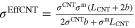


