
Abstract
The elusive 'thorium isomer', i.e. the isomeric first excited state of 229Th, has puzzled the nuclear and fundamental physics communities for more than 40 years. With an exceptionally low excitation energy and a long lifetime it represents the only known candidate so far for an ultra-precise nuclear frequency standard ('nuclear clock'), potentially able to outperform even today's best timekeepers based on atomic shell transitions, and promising a variety of intriguing applications. This tutorial reviews the development of our current knowledge on this exotic nuclear state, from the first indirect evidence in the 1970s, to the recent breakthrough results that pave the way towards the realization of a nuclear clock and its applications in practical fields (satellite based navigational systems and chronometric geodesy) as well as fundamental physics beyond the standard model (the search for topological dark matter and temporal variations of fundamental constants).
Export citation and abstract BibTeX RIS

Original content from this work may be used under the terms of the Creative Commons Attribution 3.0 licence. Any further distribution of this work must maintain attribution to the author(s) and the title of the work, journal citation and DOI.
1. Introduction
Besides the 'Hoyle state' in 12C [1], there is only one more nuclear excitation that is characterized by an own name: the 'thorium isomer' in 229Th. This term refers to the first excited state in 229Th, an exotic singularity in the landscape of presently more than 3300 isotopes with more than 176 000 excited states. The thorium isomer exhibits the lowest nuclear excitation in all presently known nuclides, four to five orders of magnitude lower than typical nuclear excitation energies. Even more than 40 years after its existence was conjectured from γ spectroscopic evidence, the quest towards precisely determining this value is still ongoing.
1.1. Historical overview
Historically, the long and winding road towards firmly establishing the thorium isomer in the conscience of the nuclear physics community began in 1976, with nuclear structure investigations on the γ-ray spectrum associated with the α decay of 233U [2]. A consistent description of the deexcitation pattern of rotational states in the daughter nucleus 229Th could only be achieved by assuming an almost degenerate excited state above the ground state in 229Th. Since no direct evidence for the ground-state decay of this new state could be resolved, the value of its excitation energy was estimated to be less than 100 eV. For more than a decade this conjecture received only little attention, while efforts continued to improve on constraining this exceptionally low nuclear excitation energy further. In 1990 the energy was determined to (−1 ± 4) eV, using differences from higher-lying γ-ray transitions (see figure 1 and energy differences Δ1 to Δ3 listed below), leading to the conclusion that the excitation energy should safely be located below 10 eV [3]. Moreover, it was concluded that this new state should be a rather long-lived isomeric magnetic dipole (M1) excitation (denoted further on 229mTh, i.e. the 'thorium isomer') with an estimated lifetime (assuming a 1 eV M1 transition) of a few thousand seconds. Refined γ-spectroscopic measurements by the same group resulted in an energy value of (3.5 ± 1) eV published by Helmer and Reich in 1994 [4]. They used the four energy differences Δ1–Δ4 indicated below of deexcitation pathways via energetic rotational states based on the (partial) nuclear level scheme displayed in figure 1, each of them indirectly indicating the energy of the thorium isomer, which still could not be resolved directly.

Figure 1. 229Th level scheme (energy units in keV) containing only levels that were used in Helmer and Reich isomer's energy determination in 1994 [4]. In square brackets the Nilsson quantum number categorization of the band-head levels is indicated. The energy gap between the 5/2+ [633] ground state and the 3/2+ [631] first excited state (both indicated in red) was calculated from this scheme in four different ways. In [4] the resulting energy value was given as (3.5 ± 1.0) eV, here the presently adopted value of 7.8 eV is indicated. Reproduced with permission from [5].
Download figure:
Standard image High-resolution imageThe value of (3.5 ± 1) eV lies below the first ionization potential of thorium given by 6.3 eV. Therefore, internal conversion, representing a potential non-radiative decay channel, was expected to be energetically forbidden, leading to an enhanced branching into radiative decay and an increased half-life of 20 to 120 h (assuming no coupling to the electronic environment) [4]. These assumptions had to be corrected later on according to further energy investigations. In particular, Helmer and Reich assumed already in their 1994 publication that 'no unique half-life' for 229mTh might exist, as this will depend on the specific electronic environment of the sample.
For more than a decade this excitation energy value served as the standard reference, leaving its trace in the literature, where the thorium isomer was for a long time dubbed the '3.5 eV isomer'. Numerous studies were conducted relating to the unique prospect of controlling nuclear matter with optical radiation. However, all experimental searches for optical emission in this energy range were unsuccessful or inconclusive.
Improved knowledge of the 229Th nuclear level scheme and its branching ratios led to re-analysis of the data from Helmer and Reich in 2005 by Guimaraes-Filho and Helene [6], which also included a correction for recoil effects, resulting in a modified value of (5.5 ± 1) eV for the excitation energy of the thorium isomer.
A paradigm change was initiated in 2007, when Beck et al published a new measurement of the isomeric energy performed with a novel pixelated, cryogenically cooled NASA x-ray micro-calorimeter, providing an energy resolution of about 30 eV [7]. Now it became possible to resolve the previously unresolved closely spaced rotational γ-ray transitions of 29.19 keV and 29.39 keV, as well as the doublet at 42.43 keV and 42.63 keV, respectively (see level scheme in figure 1 and original data in figure 2). In turn, this enabled the introduction of a new double transition energy difference to be used for the determination of the isomeric energy, according to
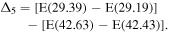
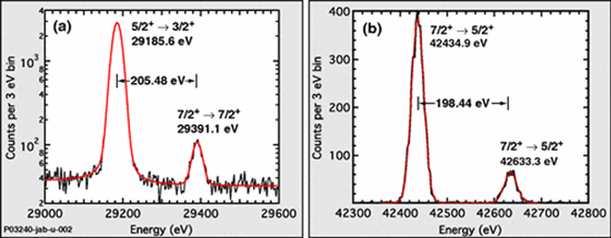
Figure 2. γ-spectroscopic data for low-lying rotational transitions in 229Th from [7], leading to the revision of the excitation energy of the thorium isomer by Beck et al in 2007. Reprinted figure with permission from [7], Copyright 2007 by the American Physical Society.
Download figure:
Standard image High-resolution imageThe γ-ray doublets around 29 keV as well as 42 keV were spectroscopically resolved for the first time. Together with a corrected branching ratio of the 29.19 keV ground-state transition this measurement resulted in the proposal of a considerably larger isomeric energy of (7.6 ± 0.5) eV [7]. This value shifted the wavelength of the isomeric ground-state transition from the previously investigated optical/near-UV range around 350 nm (corresponding to 3.5 eV) into the vacuum ultra-violet (VUV) spectral range at (163 ± 11) nm. The accordingly required a change of detection technology and likely explains the lack of direct isomer observation in earlier experiments [8–17]. Experimental studies went along with theoretical efforts to better understand the peculiar properties of the thorium isomer [18–20] or propose various ways for its population [21–28]; see also the review articles [29, 30].
Moreover, from this point on the previously expected dominance of the radiative decay channel had to face competition from the internal conversion decay channel, with the isomeric energy now placed above the first ionization potential of neutral thorium. The isomeric radiative half-life was suggested in [7] to be about 5 h.
A minor modification to this value was introduced in 2009 by the same authors [31]. While a possible non-zero branching ratio for the 29.19 keV ground-state transition was already included in their first publication, now a non-zero branching ratio for the inter-band transition from the 42.43 keV rotational band member of the ground-state band to the 229mTh isomeric band head was also introduced. The estimated value of this branching ratio is 2%, leading only to a small correction for the isomeric energy value to (7.8 ± 0.5) eV (equivalent to a VUV wavelength of (160 ± 10) nm). This is the most widely accepted isomeric energy value today, however, it has been argued that the actual uncertainty of this measurement might be potentially larger than the 0.5 eV originally quoted by the authors (representing only the statistical uncertainty, while no systematic uncertainties are given) [32].
The result by Beck et al stimulated various and intense efforts around the world towards direct observation and energy determination of the nuclear transition, with the most commonly used methods being (VUV) fluorescence detection from 229Th-doped crystals and optical excitation in trapped 229Th ions [5, 33–41]. These efforts went along with proposals of various excitation and de-excitation schemes [42–45], preparations for laser-spectroscopic studies [46, 47] and quantitative assessments of the available parameter space for half-life and excitation energy [48].
A comprehensive historical literature overview of the development from the first proposal of 229mTh to its final direct detection in 2016 is given in [5].
1.2. Potential applications of the thorium isomer
While Reich and Helmer themselves did not propose any applications for the exotic thorium isomer in their publications, their work, in particular their publication [3] from 1990 was the basis for the previously documented worldwide increasing interest, both theoretical and experimental. This led to the proposal of a broad scope of compelling applications in subsequent years. Directly responding to [3], Strizhov and Tkalya published a theoretical paper in 1991, where they discussed different decay channels of the thorium isomer [49]. Even more noteworthy, they already anticipated an increasing interest in the properties of the thorium isomer from various physics disciplines such as 'optics, solid-state physics, lasers, plasma, and others'. In the first place, however, one should mention frequency metrology, as the placement of the thorium isomer in the energy and half-life region of atomic transitions exploited for high-precision optical atomic clocks, its small relative natural linewidth of ΔE/E ∼ 10−20 (derived from the long half-life of a few 103 s [48]), and the about five orders of magnitude smaller nuclear electromagnetic moments compared to those of atoms render the thorium isomer a natural candidate for a highly precise nuclear frequency standard—a nuclear clock.
Figure 3 impressively illustrates the unique properties of 229mTh in a 2D plot of excitation energy versus half-life for all presently known nuclear isomers [50]. The thorium isomer is located far off all other excited isomeric nuclear states surrounded by typical atomic transitions, which are applied in optical atomic clocks. Thus the potential impact of 229mTh on highly precise and stable frequency metrology was already recognized early on. Amongst a list of proposed applications and access to interesting physical problems provided by the thorium isomer, such as the creation of a nuclear γ laser or studies of the decay of the nuclear isomeric level via an electronic bridge process, Tkalya et al initially mentioned the 'development of a high-stability nuclear source of light for metrology' without explicitly referring to a nuclear clock, but already pointing to the expected high (frequency) stability of the 229mTh ground state transition as one of the key ingredients for an advanced clock design offered by 229mTh [23]. Some years later the same group also discussed the decay of the thorium isomer in a solid-state environment, again anticipating one of the routes now being pursued towards the realization of a nuclear clock [26]. Based on these proposals, in 2003 Peik and Tamm finally proposed 229mTh in a metrological context as the basis of a nuclear clock, discussing both an ion-based as well as a solid-state-based approach for its realization [51].

Figure 3. Distribution of excitation energy versus half-life of isomeric nuclear states. Nuclear excitations (blue circles) exhibit typical energies in the range of a few 10 keV up to several MeV. There are only two low-energy (<1 keV) nuclear states known: 229mTh (∼7.8 eV, expected energy range indicated by blue box) and 235mU (76.7 eV). Due to the very long radiative lifetime of 235mU, only 229mTh qualifies for a direct laser excitation and hence for the development of a nuclear clock. In addition, selected clock transitions are included (red circles), which are already in use for optical atomic clocks. Reprinted by permission from Macmillan Publishers Ltd: Nature [52], Copyright 2016.
Download figure:
Standard image High-resolution imageIn conventional optical atomic clocks, the most significant perturbations from external-field induced clock frequency shifts arise due to differences in the clock state's electronic wave functions. Due to the small size of the nucleus compared to the large electron cloud, leading to excellent isolation of the nucleus from potentially perturbing external fields, the nuclear ground-state transition from 229mTh may be utilized in an optical clock of unprecedented accuracy and stability. In particular, when utilizing stretched pairs of nuclear hyperfine states of 229Th3+ in its electronic ground state (exhibiting a favorable electron configuration of a Rn noble gas core plus one valence electron), the electron cloud is the same for all clock states, leading to significant suppression of all external-field clock shifts [53]. Additionally, narrow laser cooling transitions and the large mass of thorium lend themselves to significant suppression of the second-order Doppler (time dilation) shift, a leading systematic effect in single-ion clocks. Altogether, a nuclear clock can be expected to be largely immune against external perturbations [51, 53–55]. Ultimately, a clock inaccuracy approaching the 10−20 scale (in [53] a total clock uncertainty budget of 1.5 × 10⁻¹⁹ is reported) appears viable with current ion clock technologies applied to a 229Th3+ nuclear clock system [53].
This has to be seen in the context of the rapid parallel development of atomic clocks, where the best optical atomic clocks to date exhibit total systematic frequency uncertainties as low as 9.5 × 10⁻¹⁹ [56–59].
A review of the ideas and concepts for a clock that is based on a radiative transition in an atomic nucleus rather than in the electron shell is given in [60, 61].
Similar to other ultra-precise optical clocks, a nuclear clock could become a tool to address a variety of applied as well as fundamental physical topics [62]: it could improve the precision of satellite-based navigational systems such as the GPS system [63], become instrumental in the search for dark matter [61], advance the precision achievable in geodesy [64] or even provide ultra-high sensitivity for searching potential time variations of fundamental constants [65]. There also exist proposals towards a nuclear γ-ray laser [66] (detailing the initial mentioning of this idea in [23, 67]) based on the 229mTh ground-state transition and a nuclear qubit for quantum computing [68]. Moreover, as already proposed for optical atomic lattice clocks, an ultra-precise nuclear clock based on the thorium isomer could serve as gravitational wave detector [69].
A few more details are given below for the most promising and compelling prospects for a future application of a 229mTh driven nuclear clock.
1.2.1. Satellite-based navigational systems
Precision clocks play a key role in developing increasingly accurate satellite-based navigational systems such as the pioneering Global Positioning System (GPS) or similar systems in operation or upcoming operation worldwide [63, 70–73]. The frequency of the transmitted timing signals of global navigation satellite systems (GNSS) is nowadays typically controlled via rubidium atomic clocks, being the most cost-efficient and compact atomic clocks, accompanied by cesium clocks (GPS) or passive hydrogen maser (used in the European Galileo satellite network) as master clock. While presently operational positioning systems provide an accuracy of a few meters (GPS: 3–5 m, GLONASS (Russia): 4–8 m), realizing an envisaged future accuracy in the (sub-)cm range by use of ultra-precise clocks (like state-of-the-art atomic lattice clocks or a future nuclear clock) would open up new horizons for a variety of applications such as autonomous driving, freight or component tracking, and many more (see articles compiled in [74]). The prime limitation of satellite-based navigation on the ground originates from atmospheric disturbances in the Earth's ionosphere, interfering with the timing signals broadcasted by the satellites (presently mitigated by complicated differencing schemes), while the second largest source of uncertainties stems from the clock stability onboard the satellites. Unaffected by these influences, space-based inter-satellite and space mission navigation would directly benefit from an improved clock accuracy. Moreover, a future miniaturized solid-state design of a 229mTh driven nuclear clock would offer benefits in size, weight and power, all of which are crucial for satellites and long-term space operations [75].
1.2.2. Chronometric geodesy
Highly precise clocks, like modern optical atomic clocks or potentially in the future a nuclear clock based on 229mTh, along with modern optical fiber technology, can measure the geoid, which is the equipotential surface that closely reproduces the global mean sea surface and extends to continents to a precision that competes with existing technology. Currently, the geoid is known to 30–50 cm with relatively poor resolution as a function of space and time. Techniques that provide both high lateral resolution and accuracy are based on indirect approaches. Gravity measurements from orbiting satellites provide information on the geoid through integration of the observed gravity field. Satellite measurements suffer from poor spatial resolution that is of the order of the distance between the satellite and Earth (about 400 km) and measure the attenuated gravitational field of the Earth at the location of the satellite, which suffers from aliasing due to numerous superimposed effects. Atomic clocks are emerging as a new tool to measure the geoid locally on the Earth. The best clocks at present map changes of the geopotential of the Earth with an accuracy of the order of 1 cm over an integration period of a few hours [57, 58, 76, 77]. Further proposed geophysical applications of a nuclear clock build on the effect known from general relativity that a clock operated at a frequency f and located at lower altitude, thus operating in a stronger gravitational potential, will be slowed down relative to another clock positioned at higher altitude by a relative relativistic frequency shift Δf/f, which is determined by the difference of the gravitational potential ΔU through Δf/f = ΔU/c2 with c as the speed of light [78]. With a relative frequency shift of 10−18 (representing the accuracy of the presently best atomic optical clocks) corresponding to a height difference in the gravitational field of 1 cm, an expected improvement in the future by about an order of magnitude would, e.g., provide millimetric sensitivity to a network of synchronized ultra-precise (atomic or nuclear) clocks for local modifications of the gravitational potential. Thus monitoring of the filling of volcanic magma chambers (see figure 4) or early-detected plate tectonic movements may come into reach as practical applications for a future nuclear clock based on the thorium isomer [79].

Figure 4. Potential application of an ultra-precise clock as 3D gravity sensor. A clock placed on a volcano will slow down as the magma chamber fills. A (synchronized) clock placed further away will maintain its tick rate. Reproduced from [64]. CC BY 4.0.
Download figure:
Standard image High-resolution image1.2.3. Search for topological dark matter
For decades the problem of the composition of the mass of the Universe has puzzled generations of physicists. In the standard Lambda–CDM model of cosmology, which describes well the current process of the accelerated expansion of the universe, the total mass–energy of the universe contains 5% ordinary matter and energy, 27% dark matter and 68% of an unknown form of energy known as dark energy [80, 81]. Despite a variety of observational evidence for the existence of non-luminous dark matter, i.e. a massive component of the universe that does not absorb, reflect or emit any type of electromagnetic radiation, no clear experimental signature identifying or constraining its nature has so far been achieved [82–88]. While particle physicists still strive (so far unsuccessfully [89]) to identify weakly interacting massive particles as constituents of dark matter, rooted within the concept of supersymmetry [90], alternative concepts such as topological dark matter are increasingly pursued [91]. In early cosmological times, very light fields in the initial field configuration could lead to dark matter via coherent oscillations around the minimum of their potential. Such dark matter configurations are closely related to spontaneous symmetry breakdown [92]. They are generally termed topological defect dark matter and can exhibit various different types: 0D (corresponding to monopoles), 1D (strings), and 2D (domain walls) [93, 94]. In recent years, schemes for the detection of non-gravitational effects induced by a topological defect traversing the earth have been formulated, e.g., the pulsar glitch phenomenon method [95], cw-laser interferometry methods [96, 97] and the global network of synchronized atomic magnetometers [98]. Moreover, in [91, 99] it was proposed that a network of atomic clocks could be used to search for transient signals of a hypothetical dark matter in the form of stable topological defects. The clocks will become desynchronized when a dark-matter object sweeps through the clock network. Improved sensitivity for this dark-matter detection scheme could be provided by a network of synchronized 229mTh nuclear clocks.
1.2.4. Search for time variation of fundamental constants
In several theories that unify gravity with other interactions (grand unified theories, Kaluza–Klein and string theories) the possibility of temporal and spatial variations of fundamental constants in an expanding universe is suggested [100, 101]. There are hints of a variation of the electromagnetic coupling constant, i.e. the fine structure constant α and the (dimensionless) scale parameter of the strong interaction mq,e/ΛQCD in quasar absorption spectra, big bang nucleosynthesis and data from the Oklo natural nuclear reactor [102–104]. However, so far only limits have been reported on possible temporal variations. A recent measurement of the frequency ratio of two optical clock transitions in 171Yb+ provided the most stringent, yet still compatible with zero, value so far for a potential temporal variation of the fine structure constant of  [105].
An intriguing fundamental application of the thorium isomer was proposed in 2006 by Flambaum (following an idea introduced by Peik and Tamm from 2003 [51]), suggesting quantitatively a considerably (by several orders of magnitude) enhanced sensitivity of the thorium isomer and its ground-state transition to variations of fundamental constants [65]. This triggered a lively and partly controversial debate in the literature [106–111].
The key property determining the magnitude of an expected enhancement is the difference of the Coulomb energy ΔVC between the ground and isomeric first excited state in 229Th, which together with the isomeric transition frequency ω forms the enhancement factor K according to  Ultimately, in all calculations the resulting sensitivity enhancement effect turned out to be inconclusive due to the inherently limited precision of nuclear model calculations, compared to the extremely low excitation energy of the thorium isomer. From an estimate of the change in Coulomb energy ΔVC between the 229Th ground state (229gTh) and the thorium isomer it was shown in [112] that ΔVC can reach several hundreds of keV from the polarization contribution of the Coulomb energy to the level spacing between the almost degenerate doublet of 229gTh/229mTh. Consequently, K was found to vary between ±4 × 10⁴. Determining its precise value, being decisive when planning future experiments designed to search for temporal variations of α with a 229mTh nuclear clock, has to be left to experimental efforts, requiring precise knowledge of the electric quadrupole moments of ground and isomeric states and the quadratic charge radius difference between the two [112]. We will come back to this point when discussing laser spectroscopic studies on 229mTh in section 3.
1.3. Experimental approaches towards detection and optical control of 229mTh
Basically, the excitation of the thorium isomer can be achieved via three different pathways (see figure 5). (a) Via direct excitation of the isomer from the ground state of 229Th. This could be achieved, e.g., either by using synchrotron radiation [38, 39] or via a so-called electronic bridge process (EB) [42]. In the EB process initially the electron shell will be resonantly excited, which then transfers its energy to the nucleus. Ultimately, optical control of the thorium isomer is envisaged via laser excitation. (b) Alternatively, the thorium isomer can be populated via the excitation of a higher-lying nuclear state, which then populates the isomer during its decay, similar to the indirect measurements that led to the present value of the isomeric excitation energy. For example, the 29 keV state can be excited with synchrotron radiation, subsequently populating the isomeric excited state with a probability of about 92%. Alternatively, resolving the 29.19 keV doublet in the γ energy spectrum following the α decay of 233U, corresponding to the decay into the ground and isomeric state, respectively, allows for measuring the isomeric excitation energy with high accuracy, e.g. via magnetic microcalorimeters [113, 114]. (c) A third option is exploiting the radioactive α decay of 233U (T1/2 = 1.6 105 years) or the β decay of 229Ac (T1/2 = 62.7 m). Here one capitalizes on the favorable properties of the radioactive decay modes, since the α decay of 233U proceeds with a branching ratio of about 2% through the isomeric first excited state towards the ground state of 229Th, while from work performed at the ISOLDE facility at CERN [115, 116] it can be concluded that the indirect (via higher-lying excited states) feeding of the (3/2+) isomeric first excited state in 229Th at 7.8 eV represents 13.4 % of the total beta feeding of 229Ac [50]. This may provide an alternative population scheme for the thorium isomer in the future [117].
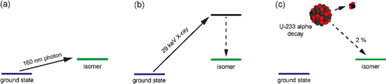
Figure 5. Different approaches for the population of 229mTh. (a) Direct excitation of the isomer by photons from the ground state. (b) Excitation of the 29 keV rotational transition, which populates the isomer with a probability of 92%. (c) Natural population of the isomer via the α decay of 233U, where the isomer is populated with a branching ratio of 2%. Reproduced from [118]. © IOP Publishing Ltd. All rights reserved.
Download figure:
Standard image High-resolution imageTypically 229Th, which was generated in the α decay of 233U, will be implanted into a VUV transparent crystal with a large band gap (larger than the excitation energy of the isomer). In a similar process the crystal can be directly doped with 233U. All of the mentioned options to populate the thorium isomer are presently experimentally investigated by different groups worldwide.
Besides undergoing γ decay the thorium isomer can also decay via internal conversion (IC) to the ground state. Here the nucleus transfers its excitation energy to the atomic shell, resulting in the emission of a shell electron. A prerequisite for the occurrence of this decay mode is an ionization energy which is smaller than the isomeric excitation energy. In the case of an assumed excitation energy of 7.8 eV this condition is only fulfilled for neutral thorium.
Electrons emitted during the IC decay of 229mTh were identified for the first time in 2016 by Wense et al [52], in turn offering the opportunity to study the isomeric energy in two ways: the most direct is the spectroscopy of IC electrons, with another option being a laser-based excitation of neutral thorium atoms. In this case the energy determination can be achieved by tuning the excitation laser.
2. Realization of the first direct detection of the thorium isomer decay
For decades the nuclear physics community seemed to chase a phantom, since the existence of the thorium isomer could only be traced back to indirect evidence, which, as strong and convincing it may have been, could not be regarded as a final and undisputable direct proof of existence. This even led to openly published doubts about the existence of this peculiar nuclear excitation [32]. Therefore, room is given in this chapter to the introduction of the rationale, the experimental setup and the results that finally settled this issue by means of a direct detection of the de-excitation of the thorium isomer.
2.1. Rationale of the experiment
The basis of the experimental setup used for identifying the decay of the thorium isomer is formed by a buffer-gas stopping cell located at the Maier–Leibnitz Laboratory in Garching. This device was initially developed for the thermalization of online produced energetic fusion reaction products with multi-MeV kinetic energies. As such the dimensions of the gas cell are oversized, for the purpose of stopping the recoil ions following the α decay of a 233U source, where only 84 keV kinetic energy need to be thermalized. When starting the project to search for the decay of 229mTh, it became obvious from various publications that prompt background accompanying the α decay of 233U gave rise to misinterpretations of the resulting fluorescence signals, leading to erroneous claims which had to be refuted [9–11, 13, 33, 34].
Therefore it appeared natural to aim at separating the α decay with all its accompanying prompt background radiation contributions from the delayed isomeric decay, which ideally should happen in an (almost) background-free environment prior to the detection of the decay products. The buffer-gas cell developed and built at the Maier–Leibnitz Laboratory of LMU and TU Munich in Garching [119] promised ideal conditions to fulfil these requirements [120]. The experimental setup was studied in simulations and the expected performance of the various components was quantified in terms of the achievable efficiencies [121].
Figure 6 shows a 3D overview drawing of the buffer-gas cell (left) and the subsequent components of the experimental setup used to generate an isotopic clean beam of 229(m)Th ions. Details on the experimental setup will be given in the following section, while a comprehensive and illustrative description of the methodology to generate the 229mTh ion beam can be found in the visualization contained in [122].
Figure 6. 3D technical drawing of the experimental setup employed for the generation of an isotopic clean 229(m)Th ion beam. It is composed (from left to right) of a buffer-gas stopping cell that houses a 233U a recoil source, a radiofrequency quadrupole (RFQ) as ion guide and phase space cooler, a quadrupole mass separator (QMS) and (behind a triodic electrode system) a multichannel-plate detector followed by a phosphor screen and a charge-coupled device (CCD) camera. For more details see the main text [123]. Reprinted by permission from Macmillan Publishers Ltd: Nature [52], Copyright 2016.
Download figure:
Standard image High-resolution image2.2. Experimental setup and procedure
2.2.1. Generation of a 229mTh ion beam
The previously described extraction scheme of 233U α recoil ions from a buffer-gas stopping cell is schematically depicted in figure 7, also indicating typical operational parameters of various DC and RF electrodes.

Figure 7. Sketch of the ion extraction system designed for the highly efficient thermalization, extraction and low-energy ion beam formation from a 233U α-recoil ion source. The optimized extraction voltages are indicated for each electrode (with RF amplitude voltages given as peak-to-peak values Vpp). The overall length of the system is about 85 cm. A description of the extraction system is given in the text [124]. 2015 © SIF, Springer-Verlag Berlin Heidelberg 2015. With permission of Springer.
Download figure:
Standard image High-resolution imageThe 233U source that serves to populate the thorium isomer via its 2% α decay branch ending in the first excited state of 229Th is mounted in the buffer-gas stopping cell and acts as an electrode of the ion-extraction system (39 V offset voltage).
In fact, three different α sources were employed in the measurements to search for the 229mTh decay. Source 1 consists of about 200 kBq 233U (UF4), evaporated onto a 20-mm-diameter stainless-steel plate. The UF4 layer thickness is 360 ± 20 nm, leading to a recoil efficiency of only about 5.3% for 229Th (in view of the short range of the α recoil nuclei of about 16 nm; ca. 10 600 recoil ions leave the source layer per second). The source material was not chemically purified before evaporation. As the isotopic material was produced around 1969, a significant ingrowth of short-lived daughter nuclides had occurred since then. Source 2 consists of 270 ± 10 kBq 234U, deposited by molecular plating [123] onto the surface of a Ti-sputtered Si wafer of 100 mm diameter. It has a thickness of 0.5 mm with a 100 nm thick layer of sputtered titanium. The active surface area of the source is 90 mm in diameter, leaving a 12 mm diameter unplated annular region in the centre. This source will later on be used as a control sample, where under identical experimental conditions no isomeric decay signal can be expected. Source 3 is a 233U source of about 290 kBq. Similar to source 2, it was deposited by molecular plating with 90 mm diameter onto the surface of a Ti-sputtered Si wafer of 100 mm diameter (and a central unplated region with 12 mm diameter). Because of the smaller source thickness, the thorium extraction rate was increased by a factor of about ten compared to source 1 and about 105 recoil ions leave the source layer per second. The isotopic material of source 3 was chemically purified before deposition by ion-exchange chromatography to remove the 233U and 232U daughter nuclides. A relative purification factor of ≥250 was found, based on a comparison of γ-energy spectra of the source material before and after chemical purification.
The α-recoil ions, which possess a kinetic energy of up to 84.3 keV for 229Th, are stopped within 1–2 cm in 32–40 mbar of ultra-pure helium. In order to guarantee the required cleanliness of the buffer gas, helium with a purity of 99.9999% is used (He 6.0), which is further purified by a catalytic purification device (designed for purification to the ppb level) and a cryotrap filled with liquid nitrogen to take care of contaminants in the gas feeding lines. The gas tubing was electropolished and the cell chamber was built to UHV standards, in order to allow for baking up to 180 °C. Hence, a typical background pressure of P ≤ 3 × 10⁻¹⁰ mbar is achieved after baking. This high cleanliness allows for an efficient extraction of α recoil ions without significant losses by, e.g., charge exchange or formation of molecules.
Being emitted isotropically into the gas volume, a conical RF + DC funnel system, consisting of 50 ring electrodes (0.5 mm and 1 mm thick, with converging diameters from 115 mm to 5 mm), is employed to guide the stopped recoil ions towards the exit from the gas cell. RF- and DC voltages are applied to this ring electrode structure. The applied RF voltages are 220 Vpp at 850 kHz, alternating in phase by 180° between neighbouring electrodes. This leads to a repelling force, preventing the recoil ions hitting the electrodes, while a DC voltage gradient of typically 4 V cm−1 (35 V to 3 V) guides the ions through the buffer-gas background towards the gas-cell exit, which is formed by a supersonic nozzle built in convergent-divergent de Laval geometry and electrically isolated in order to serve as last extraction electrode. In the region of the nozzle (0.6 mm diameter) a supersonic gas jet is formed that rips the ions off the electrical field lines and drags them with the gas jet into the subsequent vacuum chamber that houses a 12-fold segmented, 33 cm long radiofrequency quadrupole (RFQ) ion guide (rod diameter 11 mm, open inner diameter 10 mm). An RF field of 200 Vpp at 880 kHz is applied to the RFQ rods. In this extraction chamber the He carrier gas is pumped away, leaving a selectable ambient pressure of 10−2–10−3 mbar for phase space cooling.
At that stage of the ion extraction process one has to be aware that not only the desired 229Th recoil ions, but also all other daughter products from the 233U decay chain as well as sputtered 233U source nuclei will be present in the extracted ion cocktail. Therefore the next part of the experimental setup consists of a quadrupole mass separator (QMS), serving to filter out the 229Th ions of interest. The QMS consists of four cylindrical rods with 18 mm rod diameter and 15.96 mm inner rod distance, based on a design developed in [125, 126]. The length is 30 cm, with an additional 5 cm at the entrance and exit acting as focusing Brubaker lenses [127]. At the resonance frequency of 925 kHz, an RF amplitude of 600.5 Vpp and a DC voltage of 50.15 V is required for the extraction of 229Th3+ (901.5 Vpp and 75.23 V for the 2+ charge state, respectively). A voltage offset of −2 V is applied to the whole system. With this device, a transmission efficiency of about 90% with a mass resolving power of m/Δm = 240 can be achieved [126].
Behind the QMS, the extracted ions are guided by a triodic electrode structure, consisting of three ring electrodes in a nozzle-like shape. The first electrode acts as an aperture electrode to shield the RF voltages of the QMS (−2 V). A voltage of −62 V is applied to the second electrode in order to extract the ions from the QMS, while the third electrode with a 2 mm diameter opening shields the extraction voltage from the surroundings when applying −22 V.
Finally, figure 8 displays three exemplary regions of the mass spectrum as extracted and registered with a multichannel-plate detector behind the QMS and the triodic electrode system. The three panels belong to regions containing differently charged extracted ions. Clearly visible are the dominant mass peaks of 229Th and 233U, together with accompanying contributions from other α decay daughter nuclei from the 233U decay chain. Singly, doubly and even triply charged uranium and thorium ions can be identified. While for singly charged ions the extraction of 233U+ clearly dominates over a fraction of 0.37(7) % of 229Th+ (compared to the total amount of thorium ions emitted from the source), both nuclides are about equally strong extracted as doubly charged ions with a combined extraction and purification efficiency behind the triodic extraction system of (5.5 ± 1.1) % obtained for Th2+, resulting in (5.8 ± 0.6) × 102 extracted Th2+ ions per second for source 1. The high cleanliness of the buffer-gas cell manifests itself in the high extraction efficiency also achieved for triply charged ions. Here Th3+ even dominates over U3+, reaching an efficiency for Th3+ of (10 ± 2) % [124]. The efficient extraction of 229Th3+ from the LMU gas cell (representing the first efficient extraction of a triply charged ion from a buffer-gas cell reported in the literature) is of special importance, as the q = 3 charge state allows for a simple laser-cooling scheme of 229Th, as will later be required for laser spectroscopy of the thorium isomer [46]. Therefore, the direct extraction of the 3+ charge state will significantly simplify any future approach of ion cooling.
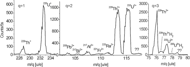
Figure 8. Selected mass scan regions of the extracted recoil ions performed with the quadrupole mass separator. The groups of 1+, 2+ and 3+ charged species are shown in the three panels. Minor shifts of the lines occur due to temperature changes during the mass scan (see text for details) [124]. 2015 © SIF, Springer-Verlag Berlin Heidelberg 2015. With permission of Springer.
Download figure:
Standard image High-resolution imageTable 1 lists the element specific extraction efficiencies determined behind the triodic extraction electrodes for source 1 [124]. Besides α daughter products from the 233U decay chain it contains also members of the decay chain of 232U, which is contained as trace contaminant in source 1.
Table 1. Extraction efficiencies of ions contained in the decay chains of 233U and 232U, as obtained from measurements behind the QMS and the triodic extraction electrode system. The values are listed separately for the 1+, 2+ and 3+ charge states [124].
| Element | 1+ [%] | 2+ [%] | 3+ [%] |
|---|---|---|---|
| Th | 0.37(7) | 5.5(11) | 10(2) |
| Fr | 21.0(42) | 16.0(32) | ≤1.5.10−3 |
| Rn | 5.8(12) | 9.3(19) | 0.053(11) |
| At | 8.6(17) | 13.0(26) | 0.033(7) |
| Po | 7.3(15) | 8.1(16) | ≤0.0021 |
| Bi | 4.3(9) | 21.0(42) | 0.083(16) |
| Pb | 2.2(4) | 11.0(22) | ≤0.012 |
The high extraction efficiency of triply charged uranium and thorium ions can easily be understood when recalling the ionization energies of the respective heavy elements contained in the 233U and 232U decay chains, as listed in table 2. Only thorium and uranium exhibit 3+ ionization potentials below the 1+ ionization potential of the helium buffer gas at 24.6 eV and can therefore energetically avoid charge exchange during thermalization and extraction.
Table 2. Ionization energies for the first three charge states of ions contained in the 233U and 232U decay chains. Only thorium and uranium exhibit 3+ ionization potentials which are below the 1+ ionization potential of helium (24.6 eV).
| Element | 1+ [eV] | 2+ [eV] | 3+ [eV] |
|---|---|---|---|
| U | 6.1 | 11.6 | 19.8 |
| Th | 6.3 | 11.9 | 18.3 |
| Ra | 5.3 | 10.1 | 31.0 |
| Fr | 4.1 | 22.4 | 33.5 |
| Rn | 10.7 | 21.4 | 29.4 |
| At | 9.3 | 17.9 | 26.6 |
| Po | 8.4 | 19.3 | 27.3 |
| Bi | 7.3 | 16.7 | 25.6 |
The total extraction time for ions from the gas cell amounts to a few ms (3 to 5 ms were obtained as extraction times behind the RFQ [128]). Faster decays of nuclear excitations already take place in the buffer-gas stopping cell.
2.2.2. Detection of the isomeric decay
Finally, behind the QMS and the extraction electrode system (with a 2 mm orifice) a microchannel plate (MCP) detector allows for the registration of the decay products emitted in the 229Th isomeric decay. The corresponding area marked by a black box at the right is shown magnified in the upper right inset of figure 6. While so far the search for signatures of the ground-state decay of the thorium isomer traditionally was focused on the detection of VUV fluorescence photons, although without providing any conclusive results, the approach followed in [52] followed a different direction: collecting the extracted ions behind the extraction triode to induce neutralization via charge exchange on the collection surface. Consequently, the internal conversion (IC) decay channel will become energetically allowed (with the first ionization potential of thorium—6.3 eV—being lower than the expected isomeric excitation energy of about 7.8 eV) and is expected to strongly dominate the de-excitation process. Therefore, the diagnostic system was laid out to detect the low-energy conversion electrons emitted in the IC decay of the thorium isomer.
Figure 9 illustrates the detection scheme. The extracted thorium ions are collected in a 'soft landing' scenario at low kinetic energy (50–75 eV, depending on their charge state of, e.g., q = 2 or 3) directly on the MCP detector surface (operated at −25 V surface voltage). Thus electron emission from ionic impact can be avoided and only the IC electron emitted after neutralization through electron capture of the ion on the detector surface will be registered via the electron cascade induced in one of the membrane channels of the MCP detector (operated in chevron geometry with +1900 V applied to the second plate). The MCP is placed in front of a phosphor screen (held at an accelerating potential of +6000 V), where the incident electron generates visible light which is monitored by a charge-coupled device (CCD) camera, allowing for spatially resolved signal detection.
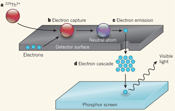
Figure 9. Illustration of the detection procedure for low-energy conversion electron from the decay of the thorium isomer. (a) Triply charged thorium ions (229Th3+) in the isomeric state impinge onto the surface of an MCP detector. (b) The ions are attracted to the surface of a detector by a swift attractive potential of about −25 V, where they capture electrons to generate neutral atoms. (c) The excited isomeric state decays through an internal-conversion process, which causes an electron to be emitted. (d) The emitted electron triggers a cascade of electrons in one of the channels of the MCP, which then are accelerated towards a phosphor screen, causing visible light to be produced that finally will be registered by a CCD camera [129]. Reprinted by permission from Macmillan Publishers Ltd: Nature [129], Copyright 2016.
Download figure:
Standard image High-resolution image2.3. Experimental results
Figure 10 shows the central outcome of the described study. Panel (a) displays a mass scan of ions extracted from the 233U source 1. An extraction rate of about 103 s−1 could be achieved for 229Th3+ [124]. Assuming that 2% of the ions are in the isomeric state [130] and also accounting for an MCP detection efficiency for low-energy electrons of about 1.5% [131], a count rate of ∼0.3 counts s−1 can be expected. Figure 10(c) shows the resulting conversion-electron signal from the decay of the thorium isomer obtained for an extraction period of 2000 s for 229Th3+ ions. Signals were acquired with a CCD camera within a centered field of view of 20 mm diameter. The spatially integrated decay count rate amounts to 0.25 ± 0.10 counts s−1, thus being in good agreement with the expectations. The MCP detector exhibits a low dark count rate of only 0.01 counts s−1 mm−2, thus leading to an excellent signal to background ratio of about 8:1. An overview of different measurements performed under the same experimental conditions is shown in figure 10(b). Each row corresponds to CCD images acquired with a specific uranium source: the upper row shows the results obtained with the 233U source 1 ('weak source'), while the bottom row shows the same for source 3, the strong (and radiochemically purified) 233U source. The middle row displays the CCD images obtained when source 2 was used, i.e. the 234U control sample, where no isomeric decay signal should be observed. The columns of figure 10 correspond to different extracted ion species, as indicated by the arrows from the mass scan. Clear signals are seen when extracting 229Th2+ and 229Th3+, as expected a weak signal from the weak source and a stronger signal from the strong 233U source (figure 10(b), first row). Strong evidence for the correlation of these signals to the decay of the thorium isomer is provided by the non-observation of a signal in case of the 234U source (leading to extracted 230Th α recoil ions). Thorium atomic shell effects, such as a long-lived atomic excitation or a chemical reaction between thorium and the MCP surface, can be thus be excluded.
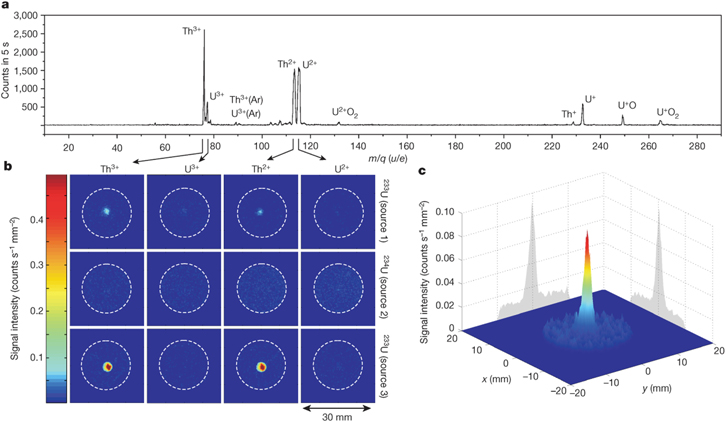
Figure 10. (a) Complete mass scan performed with the 233U source 1 [124]. Units are given as atomic mass (u) over electric charge (e). (b) Comparison of MCP signals obtained during accumulation of thorium and uranium in the 2+ and 3+ charge states (see individual extracted ions indicated on top, arrowed from the mass scan); 233U and 234U sources were used (the source number is given on the right-hand side of each row). Each image corresponds to an individual measurement of 2000 s integration time (20 mm diameter aperture indicated by dashed circles). Measurements were performed at about −25 V MCP surface voltage in order to guarantee soft landing of the ions. (c) Signal of the 229Th isomeric decay obtained during 229Th3+ extraction with source 1. A signal area diameter of about 2 mm (full-width at half-maximum) is achieved. The obtained maximum signal intensity is 0.08 counts s−1 mm−2 at a background rate of about 0.01 counts s−1 mm−2 [52]. Reprinted by permission from Macmillan Publishers Ltd: Nature [52], Copyright 2016.
Download figure:
Standard image High-resolution imageVarious confirmation test measurements were performed to assure that the observed signals from figure 10 can indeed be safely attributed to the IC ground-state decay of the 229mTh isomer. Figure 11(a) shows the result of measurements of the signal intensity at the MCP as a function of its surface voltage, comparing 229Th2+ and 233U2+. Each isotope was extracted for 1200 s for every data point. For MCP surface voltages between −100 V and −40 V, the remaining signal generated by electrons released during the impact of the incident ions decreases as the kinetic energy of the ions is reduced. While the uranium signal is effectively reduced to zero, a thorium signal remains. A sharp cut-off of this signal occurs at zero kinetic energy, when the ions can no longer approach the MCP surface. The increase of the signal intensity which occurs just before the cut-off can be attributed to IC electrons which are repelled by the triodic extraction electrode system and back-attracted into the MCP surface. The absence of a similar sharp cut-off for uranium clearly excludes any cause of the signal by ionic impact or charge state effects. Moreover, these measurements also exclude all potential background caused by the setup components, which would be constant throughout the measurements.
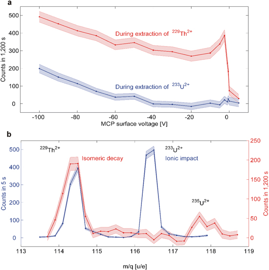
Figure 11. Background corrected 229Th isomeric decay signals acquired in two different scenarios to support the assignment of the signal from figure 10 as direct decay signature of the thorium isomer. (a) 229Th2+ signal (red) compared to 233U2+ (blue) as a function of the MCP surface voltage. Errors are indicated by shaded bands. (b) Signal of extracted ions as a function of the mass-to-charge ratio behind the QMS for MCP surface voltages of −25 V (isomeric decay, red) and −2000 V (ion impact, blue). Note the different integration times and axis scales. Besides the signal at 114.5 u/e (corresponding to 229Th2+), a further signal at 117.5 u/e occurs, which originates from the isomeric decay of 235U (239Pu was shown to be contained in the source material by α spectroscopy [124], the isomer is populated by a 70% decay branch and the extraction rate is too small to be visible in the ion-impact signal) [52]. Reprinted by permission from Macmillan Publishers Ltd: Nature [52], Copyright 2016.
Download figure:
Standard image High-resolution imageA second confirmation measurement is shown in figure 11(b). Here the MCP signal intensity is plotted as a function of the selected mass-to-charge ratio m/q for MCP surface voltages of −25 V and −2000 V. At a strongly attractive surface voltage of −2000 V (blue curve), the expected ionic impact signal is observable and the 233U2+ and 229Th2+ mass peaks are of comparable intensity, as already observed in the mass scan of ions extracted from the buffer gas cell displayed in figure 8. At a surface voltage of −25 V, which corresponds to the 'soft landing' condition for ions impinging onto the MCP surface (red curve), the 233U2+ mass peak completely vanishes, since no ionic impact signal is detected. 229Th2+, in contrast, reveals a remaining component, which is clearly restricted to the 229Th2+ mass peak and thus once more supports the interpretation as IC ground-state decay of the thorium isomer. It should be noted that the isomeric signal (red curve) in figure 11(b) also shows an indication of the second presently known low-lying nuclear isomer 235mU (t1/2 = 26 min, excitation energy 76 eV, as already included in figure 3) originating from a minor contamination of the source material with 239Pu.
One may think of additional classes of potential background contributions (such as the short-lived daughter nuclides), which are thoroughly discussed and excluded in [52], mostly by several complementary arguments and findings.
As a final outcome of this study it can be concluded that the observed signal shown in figure 8 indeed represents the first direct measurement of the de-excitation of the 229mTh isomer, thus bringing a 40-year-old worldwide search to a successful completion. Consequently, this breakthrough finding opens the door for further activities targeting a characterization of the thorium isomer's properties (as addressed in the following chapter), on the road towards the ultimate goal of realizing a nuclear clock based on the thorium isomer.
3. Experimental characterization of the isomer's properties
Following the direct identification of the thorium isomer's ground-state decay, the natural next experimental steps focused on a characterization of its properties beyond the coarse constraints given in [52] with the range of excitation energies from 6.3 eV–18.3 eV (motivated by the first and third ionization potentials of thorium) and a lifetime of the (ionic) thorium isomer of >1 min (limited by the ion's lifetime in the vacuum conditions of the so far used radiofrequency quadrupole.
3.1. Half-life of the neutral isomer
Applying the same experimental technique to populate the thorium isomer as used in [52], the half-life of 229mTh could be addressed [132]. The scheme of the measurements is depicted in figure 12. The 12-fold segmentation of the RFQ was exploited to realize a bunched extraction by operating it as a linear Paul trap. Each segment can be set to an individual DC offset. Typically, a voltage gradient of −0.1 V cm−1 was applied to the first nine segments, ranging from 32.0 V to 30.2 V. The 10th and the 11th segment were set to 28.0 V and 25.0 V, respectively. The DC offset of the last segment is switchable within 0.1 μs with a fast solid-state high-voltage switch between 34.0 V and 0 V. It is thereby possible to create a potential well to trap and cool the extracted ions in the region of the 11th segment, then release them within a fraction of a μs and thus create a short ion bunch. While the ions were cooled in the trap for about 0.5 s and released, the source was set to a blocking DC offset of 40 V. At this point still all α-decay daughter nuclei are contained in the ion bunch and will subsequently be filtered according to a selectable mass-to-charge ratio by the quadrupole mass separator (QMS).

Figure 12. (a) Illustration of the production and detection scheme of 229mTh reported in [114], now used for determining the half-life of 229mTh. An ion beam is formed from 229(m)Th ions recoiling from a 233U α-recoil source. As long as 229mTh remains in a charged state, the lifetime is longer than 1 min. When the ions neutralize (e.g. by collecting the ions on a metal surface) internal conversion is triggered and the lifetime is reduced to the range of μ-seconds. The emitted IC electron can be detected. (b) Scheme of the experimental setup used for lifetime measurements following bunched extraction from the RFQ. Reprinted figure with permission from [132], Copyright 2017 by the American Physical Society.
Download figure:
Standard image High-resolution imageThe ion bunches used in these measurements exhibit an ion time-of-flight width of about 10 μs and contain about 600 and 800 229(m)Th ions in the 2+ or 3+ charge state, respectively. Figure 13 shows a Monte-Carlo simulation of the expected decay time characteristics of the thorium isomer for a bunched ion accumulation on an MCP detector. It was assumed that 2% of the ions are in the isomeric state and that the detection efficiency ratio between low energy electrons and ions amounts to a factor of 25. The MCP time signal from several bunches recorded with 233U3+ ions was used as an input for the bunch shape and the isomeric decay time characteristics were simulated, assuming a half-life of 7 μs. The grey curve in figure 13 represents the isomeric decay signal, the red curve the ionic impact signal and the blue curve represents the total signal that would be recorded in a measurement. An isomeric decay signal that remains after the ionic impact signal caused by the accumulation of the ion bunch is clearly visible.
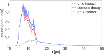
Figure 13. Simulation of the isomer decay time characteristics of 229Th bunches. The simulation is based on a measured bunch shape and the assumption that 2% of the 229Th ions are in the isomeric state with a half-life of 7 μs after neutralization. The electron detection efficiency is assumed to be 25 times larger than the ion detection efficiency. Reprinted with permission from [132], Copyright 2017 by the American Physical Society.
Download figure:
Standard image High-resolution imageFigure 14 shows the correspondingly measured data, comparing the decay time characteristics of triply charged 229Th and 233U ion bunches, respectively. While 233U ions generate only signals from ionic impact (red curve), 229Th3+ features precisely the signal shape expected from the simulations, including the isomeric decay tail. A further support of this interpretation is concluded from the right panel of figure 14, where the decay time signals of 229(m)Th2+ ion bunches were measured as a function of different kinetic energies. With decreasing kinetic energy only the ionic impact signal is consecutively reduced, while the isomeric decay tail remains unchanged. The shift of ≈1 μs in the time-of-flight signal of the ionic impact between 229(m)Th3+ and 233U3+ is due to the mass difference of 229(m)Th and 233U.

Figure 14. Left: measurement of the isomeric decay with a bunched 229(m)Th3+ ion beam (red). The blue curve shows a comparative measurement with 233U3+. Right: decay time signals obtained when collecting 229(m)Th2+ ion bunches with different kinetic energies. The isomeric decay signal strength remains constant in all measurements, while the ionic impact signal decreases with the kinetic energy of the ion bunch. Reprinted with permission from [132], Copyright 2017 by the American Physical Society.
Download figure:
Standard image High-resolution imageAs further evidence for the detection of the isomeric decay, excluding any chemical effects, figure 15 displays comparative measurements with bunched (a) 229(m)Th2+ and (b) 229(m)Th3+ ion beams (red curves), together with data from 230Th2+,3+ ion bunches, extracted from a 234U α-recoil source (blue curves). As both measurements were performed under similar conditions, the absence of an exponential decay tail in 230Th ions corroborates the origin of such signals beyond the ionic impact peak as resulting from the decay of the thorium isomer 229mTh.

Figure 15. Measurement of the isomeric decay with a bunched (a) 229(m)Th2+ and (b) 229(m)Th3+ ion beam (red curves). Corresponding comparative measurements performed with 230Th2+ and 230Th3+ are also shown as blue lines. Reprinted with permission from [132], Copyright 2017 by the American Physical Society.
Download figure:
Standard image High-resolution imageIn order to derive the half-life t1/2, a linear function ![$\left[f\left(t\right)=\,-\left(\mathrm{ln}\,2/{t}_{1/2}\right)\,t+c\right]$](https://content.cld.iop.org/journals/0953-4075/52/20/203001/revision2/jpbab29b8ieqn3.gif) was fitted to the logarithm of the registered number of counts N(t) in the decay curve. Half-lives of t1/2 = 6.9 ± 1.0 μs and t1/2 = 7.0 ± 1.0 μs were obtained for measurements performed with 229(m)Th2+ ions and 229(m)Th3+ ions, respectively. The corresponding plots and fit functions are shown in figure 16.
was fitted to the logarithm of the registered number of counts N(t) in the decay curve. Half-lives of t1/2 = 6.9 ± 1.0 μs and t1/2 = 7.0 ± 1.0 μs were obtained for measurements performed with 229(m)Th2+ ions and 229(m)Th3+ ions, respectively. The corresponding plots and fit functions are shown in figure 16.
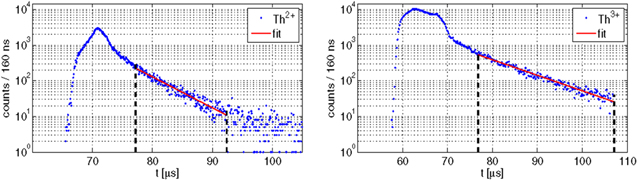
Figure 16. Temporal decay characteristics for 229(m)Th2+ (left) and 229(m)Th3+ ions (right) together with the fit curves (red) applied to determine the isomeric half-life of 229mTh after charge neutralization on the MCP detector surface. The fit range is indicated by the vertical dashed lines. Reprinted with permission from [132], Copyright 2017 by the American Physical Society.
Download figure:
Standard image High-resolution imageThe determined short half-life of about 7 μs agrees nicely with the theoretically expected drastic lifetime reduction of the thorium isomer in the case of IC decay by about nine orders of magnitude [20, 48]. This indicates an internal conversion coefficient (i.e. the ratio between the number of decays via electron emission Ne and the number Nγ of decays via gamma emission) αICC = Ne/Nγ ∼ 109. Nevertheless, a caveat has to be issued, as the lifetime of the isomer will depend on the electronic environment of the nucleus. Thus it has to be expected that the lifetime is affected by the chemical structure of the specific surface used to neutralize the ion and hence induce IC decay. To measure the lifetime of neutral isolated 229mTh, the ions need to be neutralized without getting into contact with any surface. Such a scenario will be discussed later. In addition, measurements were also performed while extracting 229Th1+. However, no isomeric signal could be obtained in this case, potentially indicating a fast de-excitation branch. This is still the subject of ongoing experimental investigations.
The following paragraph looks at the question of how to identify an optical excitation of the thorium isomer. With the newly acquired knowledge on the thorium isomer the initially far-fetched goal of a nuclear clock becomes more within reach, and with it the question of how to identify a successful nuclear excitation given that an optical control (i.e. excitation via suitable laser light) of 229mTh can be realized. In 2003, Peik and Tamm proposed a solution for this topic along with their proposal of a nuclear clock based on isolated ions [51]. Laser excitation of the 229Th nucleus into the isomeric first excited state can be detected via a double-resonance method, analog to Dehmelt's 'electron shelving' scheme for the detection of the excitation of metastable states in the atomic shell of individually trapped ions. The method builds on probing the hyperfine structure of a transition in the electron shell [51, 133, 134]; the corresponding scheme is depicted in figure 17. Starting from a 229Th nucleus in its ground state (see the left-hand side of figure 17, where α and β denote nuclear and electronic level properties, respectively), a first laser with frequency ω1 is tuned on a closed two-level electric–dipole transition in the electronic shell. The atom will respond by continuously emitting scattered resonance fluorescence photons. If now the excitation of the thorium isomer will be achieved by a second laser with frequency ω2, the nuclear moments and the nuclear spin will change. Consequently, the hyperfine splittings and the total angular momenta of the electronic levels will also change and the first laser previously being locked on the two-level electronic system in the nuclear ground state will not any longer be on resonance. Thus a drop of the fluorescence intensity will be registered. For an individual 229Th ion the cyclic excitation and decay of the isomeric first excited nuclear state will result in a periodic modulation of the resonance scattering fluorescence intensity. Similar periodic excitation and interrogation schemes are routinely used in high-resolution laser spectroscopy of trapped ions [134].
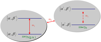
Figure 17. Schematics of the nuclear-electronic double-resonance method proposed by Peik and Tamm for the identification of an optical excitation of the thorium isomer: a first laser drives a two-level system of the electronic shell of the ground state of 229Th at a frequency ω1. The resulting resonantly scattered fluorescence intensity will drop once ω1 falls out of resonance after an excitation of the isomeric first excited state by a second laser with ω2. Labels α and β denote the nuclear and electronic properties, respectively. Adapted from [51]. © IOP Publishing Ltd. All rights reserved.
Download figure:
Standard image High-resolution imageThorium is very well suited for such a diagnostic scheme, while at the same time offering options for laser cooling (aiming to control the Doppler broadening of the isomeric ground-state transition), since Th3+ exhibits a convenient electronic level scheme with a Rn-like core plus one valence electron. However, until recently, this elegant method had to stay a conceptual option in the context of the thorium isomer, due to the lack of relevant nuclear structure information, particularly any knowledge on the hyperfine structure of 229mTh.
3.2. Laser spectroscopic determination of the hyperfine structure of the thorium isomer
The previously described method to extract 229(m)Th ions from a 233U source was recently applied to a first laser spectroscopic study in 229mTh, aiming to decipher the hyperfine structure of the thorium isomer as a prerequisite for advancing on the way towards the nuclear clock. Collinear laser spectroscopy in a linear Paul trap was performed by the team of the Physikalisch-Technische Bundesanstalt (PTB) in combination with the 229(m)Th beam provided by the Munich group, succeeding in resolving the hyperfine components of the ground and isomeric states of 229Th2+, respectively [135].
A Doppler-free two-step laser excitation scheme (J = 2 → 1 → 0) was chosen, as illustrated by the transitions highlighted in the electronic configuration scheme of Th2+ shown in figure 18. A first laser at 484 nm was applied to excite ions from a narrow velocity class of the broad thermal line profile of the initial thermally populated state (J = 2, 63 cm−1) to an intermediate state (J = 1, 20711 cm−1). This laser was detuned in 35 steps of 120 MHz width across the thermal profile. Subsequently, the intermediate state was probed by a second tunable laser at a wavelength around 1164 nm, inducing resonant excitations to the final state (J = 0, 29 300 cm−1). For each of the 35 steps of the first laser, a continuous scan over a frequency range of more than 4 GHz was performed with the second laser in collinear co- and counter-propagating laser beam geometry along the trap axis to detect the hyperfine structure resonances. A third external-cavity diode laser at 459 nm was used for single-photon excitation of Th2+ from the (J = 4, 0 cm−1) ground state to the (J = 4, 21 784 cm−1) state to monitor the number of trapped Th2+ ions via fluorescence detection registered at decay channels spectrally separated from the wavelengths of stray laser light.
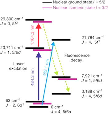
Figure 18. Transitions and electronic configurations of Th2+ levels relevant for the two-step collinear laser spectroscopy experiment performed to resolve the hyperfine splitting components of the thorium isomer. Reprinted by permission from Macmillan Publishers Ltd: Nature [135], Copyright 2018.
Download figure:
Standard image High-resolution imageBased on the nuclear ground-state spin I = 5/2 of 229Th and I = 3/2 for the thorium isomer, nine (for the ground state) and eight (for the first excited isomeric state) hyperfine splitting (HFS) components can be expected. Figure 19 shows an exemplary excitation spectrum for a selected detuning step of the first laser of—260 MHz relative to the centroid of the 229Th HFS structure.
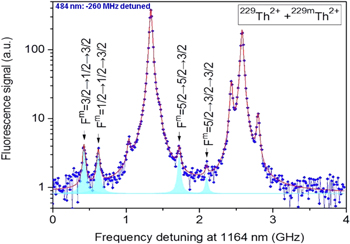
Figure 19. Hyperfine structure resonances of the 229Th nuclear isomeric and ground states. Two-step HFS excitation resonances of the thorium isomer are marked in cyan. The first laser has been stabilized at −260 MHz relative to the 229Th HFS center, while the second laser was scanned. The unlabelled peaks belong to the ground state. Reprinted by permission from Macmillan Publishers Ltd: Nature [135], Copyright 2018.
Download figure:
Standard image High-resolution imageWhile the strong resonance peaks belong to the HFS components of the ground state, the peaks marked in cyan could be observed for the first time, representing members of the HFS multiplet of the thorium isomer. From the eight expected resonances seven could be clearly resolved, while the signal-to-background ratio did not allow for observing also the weakest member of the multiplet. These findings allow for a direct confirmation of the spin assignment for the thorium isomer of I = 3/2. From the energy shift of an individual electronic level due to the HFS the hyperfine constants A (representing the magnetic dipole interaction) and B (standing for the strength of the electric quadrupole interaction) could be extracted according to
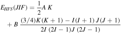
with K = F(F + 1) − J(J + 1) − I(I + 1) [136, 137]. For the intermediate state at 20 711 cm−1 the following values for the hyperfine constants were determined as listed in table 3.
Table 3. Hyperfine constants of 229Th2+ and 229mTh2+ for the electronic level 20 711 cm−1 (J = 1). [135].
| Nuclear ground state | Nuclear isomeric state | ||
|---|---|---|---|
| A [MHz] | B [MHz] | Am [MHz] | Bm [MHz] |
| 88(4) | 897(14) | −151(22) | 498(15) |
The hyperfine constants A and B allow for the first time access to the nuclear moments of the thorium isomer. From the measured ratio Am/A = −1.73(25) the magnetic dipole moment μm of the isomer was inferred as μm = μAm/A Im (AI), where μ indicates the magnetic moment of the ground state, while I and Im represent the nuclear spins of ground and isomeric states, respectively. The nuclear magnetic dipole moment μ of the ground state is known as  (μN denoting the nuclear magneton) from measurements and calculations of the HFS in [46, 138]. Hence the magnetic dipole moment of the thorium isomer follows as
  The spectroscopic electric quadrupole moment of the isomeric state
  was determined from
  where Qs is the spectroscopic quadrupole moment of the ground state, represented by the weighted mean of the two reported experimental values so far [46, 138, 139]. Thus
  follows as
  = 1.74(6) eb [135]. Furthermore, from the spectroscopic quadrupole moment the intrinsic quadrupole moment Q0 can be derived according to
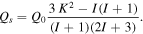
For 229Th Q0 results as  for the isomeric state and
  for the ground state, indicating an almost identical prolate deformation for the two close-lying configurations in agreement with expectations. Figure 20 summarizes all presently known information on the nuclear structure of the ground-state doublet in 229Th.
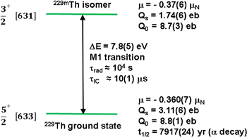
Figure 20. Properties of the 229Th ground state doublet. Nuclear levels are given with their spin, parity and dominant Nilsson configuration. μ: magnetic moment, Q: electric quadrupole moment (Qs (Q0): spectroscopic (intrinsic) quadrupole moment).
Download figure:
Standard image High-resolution imageProgress on our understanding of the nuclear structure of the thorium isomer could also be achieved on the theoretical side, with Minkov and Pálffy showing in [140] that the presence and decay of the isomer can only be accounted for by the Coriolis mixing emerging from a remarkably fine interplay between the coherent quadrupole–octupole motion of the nuclear core and the single-nucleon motion within a reflection–asymmetric deformed potential.
Moreover, from the isomeric shifts determined for the two laser excitation steps relative to the centers of the hyperfine structure, together with the isotopic shift between 229Th2+ and 232Th2+, the difference of the mean-square nuclear charge radii of the isomeric first excited and nuclear ground state in 229Th could be determined in [135] as

As mentioned earlier, from the electric quadrupole moments and nuclear charge radii the difference of the Coulomb energies of ground and isomeric excited state in 229Th can be derived according to
as given in [135] and based on [109]. Thus the sensitivity enhancement factor K = ΔVC/ω for potential variations of fundamental constants could for the first time be accessed experimentally. The Coulomb energy difference was determined as  [135]. This value is dominated by the experimental uncertainty of the electric quadrupole moment ratio
  of ±4%, preventing a conclusive result on K that could quantitatively confirm the expected considerably enhanced sensitivity of 229mTh compared to atomic systems for temporal variations of the fundamental constants.
In view of the importance for the sensitivity to variations of fundamental constants, soon after an updated value of the mean square charge radius difference between ground and first excited state in 229Th was derived through improved isotope shift calculations in Th+ and Th2+ including the specific mass shift, using a combination of configuration interaction and all-order linearized coupled-cluster methods [141]. Measurements of the hyperfine structure of Th2+ and isotopic shift between 229Th2+ and 232Th2+ was performed to extract the difference in root-mean-square radii as δ〈r2〉232,229 = 0.299(15) fm2.
This allowed for an updated value for the mean-square radius change between 229Th and its low-lying isomer 229mTh, since the latter is derived from δ〈r2〉232,229 and the ratio of the isomeric line shift and the isotopic shift between 232Th and 229Th. Using the ratio of the isomeric and isotopic shifts given in [135] and the improved value for δ〈r2〉232,229 finally resulted in δ〈r2〉229m,229 = 0.0105(13) fm2, which is in agreement with the value derived in [135], but with about 30% improved precision.
It remains for future improved studies to reduce the experimental uncertainty and to allow for unveiling the true potential of the thorium isomer for studies of fundamental physics beyond the Standard Model.
3.3. Measurement concepts for the excitation energy of the thorium isomer
Now that key properties of the thorium isomer could be characterized, a precise determination of the isomer's excitation energy remains the foremost task to be accomplished on the road to an all-optical control of the nuclear clock transition in 229Th.
In 2018, a claim was filed in [142] (non-peer reviewed) on the determination of the energy and half-life of the thorium isomer. Experimental studies were presented, where from a complex multi-step process seemingly properties of the thorium isomer were determined with high precision: E* = 7.1 eV and t1/2 = 1880(170) s. In the first stage 229Th nuclei were excited via inverse internal conversion to the low-lying isomeric level in a plasma that was formed by pulsed laser ablation from a 229Th-containing target surface, followed by an extraction of (excited) thorium ions from the plasma by an external electrical field and subsequent implantation into a thin SiO2 film grown on a silicon substrate (a dielectric material with a band gap of about 9 eV). During the second stage the gamma decay of isomeric nuclei was indirectly registered, via photo-electron spectroscopy after emission from the silicon substrate. Substitution of the photon registration by the electron detection was used to increase the signal strength. Finally, during the third stage of the experimental procedure, the electron spectrum from a standard Xe VUV source was obtained that allowed determination of the initial energy of the fluorescence photons.
On the one hand, this scheme requires a sequence of experimental processes to work altogether as assumed; some of them have so far only been studied theoretically (such as nuclear excitation by inverse internal conversion) and have not yet been experimentally demonstrated (such as the survival of the isomeric excitation during implantation into the SiO2 matrix without undergoing internal conversion decay). Moreover, the experimental procedure described in [142] relies on radiochemically non-purified target material, leaving the possibility of observing decays from short-lived α-decay daughter products (like 221Fr). While to our knowledge this shortcoming could be removed in follow-up experiments, issues with the non-exponential decay time behaviour still render this claim controversial, and strongly seeking experimental confirmation, preferably also from complementary experimental approaches.
From the experiments leading to the first identification of the direct ground-state decay of the thorium isomer it seems natural to proceed in a direction that uses the identified IC decay channel to tackle the challenge of the excitation energy determination, which at first glance 'just' means measuring the energy of IC electrons emitted from the ground-state de-excitation after charge neutralization of 229mTh ions. However, measuring precisely the kinetic energy of low-energy electrons in a range of 1–2 eV is not a trivial task, due to the low achievable count rate in the region of interest.
The general idea of performing internal conversion electron spectroscopy of 229mTh is to guide the extracted, mass-separated and bunched ions towards an electron spectrometer, where they will be neutralized, thereby triggering the IC decay and to measure the subsequently emitted conversion electrons. A first simulation study of this approach was performed by Seiferle et al in [143], where neutralization of the 229mTh ion beam was assumed to happen on a metallic catcher surface. Subsequently, IC electrons would be guided into a magnetic-bottle type electron spectrometer [144, 145]. In such a spectrometer, electrons are collected and collimated by a magnetic gradient field. The electron energy can then be determined by applying retarding electrical fields, resulting in an integrated energy spectrum, where all electrons are counted, whose kinetic energy is sufficient to pass the retarding fields that are applied via high-transmission grids, thus allowing them to reach an MCP detector where they are finally registered. It could be shown in [143] that such a scenario would not be influenced by properties of the sample material affecting the absolute achieved energy value, since only the maximum kinetic energies of the electrons and no specific binding energies of electrons in the sample are measured. Therefore, the cleanliness of the sample surface would not affect the energy measurements and an achievable precision of the energy determination of around or even better than 0.1 eV was concluded. However, the decay properties of 229mTh will not be completely independent on the chemical environment and the electron orbital structure on a solid surface. Potential excitations of surface orbitals by ionic impact could affect the determination of the IC electrons' kinetic energy.
In order to avoid any such issues, contact-free measurement is needed. This can be achieved with an experimental setup as sketched in figure 21 [146]. Incident 229(m)Th ions will not be collected on a metallic catcher surface, but rather be neutralized in flight while traversing a thin foil (not shown in the figure). Thus IC decay will be induced and conversion electrons emitted will enter an inhomogeneous magnetic field region created by a strong permanent magnet (about 200 mT in a distance of 2 mm above the magnet's cone tip), designed to form a collection region for IC electrons that will be focused into the solenoidal field of the electron spectrometer.

Figure 21. Sectional view of the magnetic-bottle type retardation electron spectrometer. The left panel (a) shows an overview of the spectrometer, with the permanent magnet, the solenoid coil, the retarding field unit and the MCP detector. The region of electron emission as well as a helical electron trajectory with its pitch angle θ is indicated. The right panel (b) shows a detailed view of the retarding field unit. The positions of the gold grids are indicated by arrows. Reproduced with permission from [146].
Download figure:
Standard image High-resolution imageThe homogeneous solenoidal magnetic transport field (strength: about 2 mT) is generated by a Kapton isolated copper wire, which is wound around a cylindrical aluminum body. For a proper shielding of external magnetic stray fields, the solenoid flight tube is surrounded by a 3 mm thick μ-metal layer. Electrical retarding fields are generated by a retarding field unit that consists of 12 concentric ring electrodes. Gold grids are sandwiched between the two central electrodes and are placed at the entrance and exit of the unit. A sectional view is shown in figure 21(b). The retarding voltage (which typically ranges between 0 V and −10 V) is applied to the central electrodes and the entrance and exit electrodes are set to ground potential.
The energy resolution of the spectrometer was measured with argon and neon as calibrant gases, using a He discharge lamp. Figure 22 displays the resulting calibration spectra. When argon is used as calibrant gas, the He radiation (He Iα at Eγ = 21.218 eV) causes ionization with electron emission energies of 5.459 eV (Ar+ 2P3/2) and 5.281 eV (Ar+ 2P1/2), respectively. The right panel shows the corresponding smoothed integral electron energy spectrum as the red line, together with the derivative of the raw data and a fit curve. In order to ionize neon, He Iβ radiation at Eγ = 23.085 eV is used. As can be seen in the left panel of figure 22, electrons are emitted with kinetic energies of 1.522 eV (Ne+ 2P3/2) and 1.425 eV (Ne+ 2P1/2).

Figure 22. Electron energy calibration spectra measured with the magnetic bottle electron spectrometer and recorded with neon (left) and argon (right) as calibrant gases ionized by a helium discharge lamp. For better visualization, the raw data counts, as well as the derivative counts, were normalized to their maximum. The voltage bin width after rebinning amounts to 6 mV and 4 mV for the neon and argon measurement, respectively. Note that for the argon measurement the difference between the raw data and the smoothed data is not visible. Reproduced with permission from [146].
Download figure:
Standard image High-resolution imageAlso here the narrowly spaced transitions can clearly be resolved and in total a relative energy resolution of the spectrometer of better than 3% (ca. 50 meV at 1.5 eV kinetic energy) is reached. Thus it can be expected that the precision reachable for determining the excitation energy of the thorium isomer will not be limited by the spectrometer resolution.
3.4. A laser excitation scheme for 229mTh
The rapid progress achieved in recent years in characterizing the properties of the thorium isomer has boosted the quest towards a precise determination of its excitation energy, still regarded as mandatory prerequisite for building a customized laser system able to optically control the nuclear clock transition in 229mTh. However, contrary to this paradigm, von der Wense et al showed in [147, 148] that the newly acquired knowledge on the decay behavior of the thorium isomer can be exploited to realize a direct laser excitation scheme for 229mTh using laser technology that already exists. This idea makes use of the fast (lifetime of ∼10 μs) non-radiative IC decay channel of neutral 229mTh for the isomer detection. Being about nine orders of magnitude faster than the (presently still unobserved) radiative decay channel, the decay by internal conversion allows for triggering the detection of the isomeric decay in coincidence with the laser pulses. Consequently, the signal-to-background ratio can be considerably improved, while at the same time enabling measurement times of only a few days. Figure 23 illustrates the underlying concept for laser excitation and electron detection: pulses from a tunable VUV laser system irradiate a thin (few nm) 229Th layer deposited on a gold surface. If the laser wavelength matches the resonance condition for the isomeric excitation, subsequent de-excitation will occur via internal conversion due to the low work function of metallic thorium of 3.7 eV [149], much below the excitation energy of 229mTh expected around 7.8 eV. The 229Th sample is placed in a magnetic-bottle type electron spectrometer similar to the one discussed in the previous section.
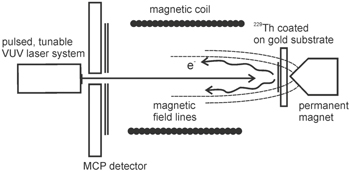
Figure 23. Schematic drawing of the experimental concept for a direct laser excitation of the isomeric state in 229Th, according to [147] (for details see text). Reprinted figure with permission from [147], Copyright 2017 by the American Physical Society.
Download figure:
Standard image High-resolution image
The electron transport and detection efficiency originates from an interplay between the electrons' kinetic energies, the strengths and geometrical orientations of the involved magnetic fields (strong inhomogeneous collimation field: ca. 200 mT, weak cylindrical transport field: ca. 2 mT), the diameter of the laser focus that defines the IC electron source diameter (ca. 1 mm), the orientation of the initial velocity vector of the IC electrons relative to the magnetic transport field axis and the smallest diameter along the transport path of the gyrating electrons, which is the MCP detector's surface diameter of 27 mm.
Thus preferably low-energy electrons (below about 1 keV kinetic energy) will be able to follow the magnetic field lines and be registered at the MCP detector, while the high-energy background will be efficiently suppressed, resulting in a high signal-to-background ratio of about 7 × 10⁴ [147].
As demonstrated in a detailed calculation in [147], using a VUV laser system as described in [150], with a pulse energy of EL = 10 μJ around 160 nm, a bandwidth of ΔνL = 10 GHz, a pulse duration of TL = 5 ns and a repetition rate of RL =10 Hz, allows for a total measurement time of less than three days for scanning an energy range of 1 eV. The achievable resolution would be below 40 μeV.
This technique would be suitable to realize a first proof-of-principle for direct laser excitation performed on 229mTh. The isomeric excitation energy could be determined to about the laser linewidth of 10 GHz (corresponding to an energy of 4 × 10⁻⁵ eV), which is five orders of magnitude better than our present knowledge, but still about another nine orders of magnitude away from the ultimate goal of applying the 229mTh ground-state transition as the ultra-precise nuclear frequency standard. Therefore, the described measurement would act as a doorway to constrain the isomeric energy precisely enough to customize a laser system with a narrower bandwidth, in order to further reduce the energy uncertainty.
4. Concluding remarks and further perspectives
After decades of searching for the 'smoking gun' of direct evidence of the existence of the elusive 229mTh isomer, huge progress has been achieved in recent years. First and unambiguous direct identification of the ground state decay of 229mTh was achieved, not, in contrast to global expectations and search scenarios, in the radiative decay channel of VUV fluorescence, but rather in the internal conversion (IC) channel via the detection of conversion electrons. The experimental method was based on the conventional population of the thorium isomer via a 2% decay branch from the α decay of 233U. However, the novel feature was to spatially decouple the population of the isomer from its decay by using a buffer-gas stopping cell and subsequent ion transport (and mass separation) devices. Thus an isotopically clean 229(m)Th ion beam could be generated and background-free IC electron detection on a multichannel-plate detector was realized. The search phase was followed by a characterization phase, aiming at constraining the decay properties of the thorium isomer. While the expected long radiative half-life of the charged isomer with up to 104 s was not accessible in the framework of the above-mentioned measurements, due to lifetime limitations imposed by the high-vacuum conditions, neutral 229mTh atoms undergoing IC decay exhibit an expected drastic reduction of the lifetime by about nine orders of magnitude. Indeed this could be experimentally confirmed by realizing a pulsed extraction of thorium ions from the gas cell and mass separator, resulting in a half-life of neutral 229mTh atoms on a metallic surface of 7(1) μs, agreeing nicely with theoretical expectations of an internal conversion coefficient αICC ≈ 109. In order to realize a 229mTh-based nuclear clock, however, it will be essential to exploit the expected long lifetime of charged thorium isomers. Ionic lifetimes of several hours can only be experimentally accessed under ultra-high vacuum conditions. Therefore, a cryogenically operated Paul trap will be the method of choice, already being under preparation for measurements of the ionic lifetime of 229mTh as well as an instrumental backbone for future laser manipulation (cooling and excitation) of thorium isomers.
Insight into the nuclear structure of the thorium isomer was gained via collinear laser spectroscopy, allowing researchers to resolve the hyperfine structure of the thorium isomer. Based on this knowledge a double resonance technique proposed by Peik and Tamm, more than 15 years ago, could be applied in the future to monitor an optical excitation of the thorium isomer as another ingredient of a nuclear clock. From the laser spectroscopic measurements the isomeric nuclear spin of I = 3/2 could be confirmed and quantitative information on the magnetic dipole and electric quadrupole moments was obtained, as well as on the difference of the mean square charge radii of ground and isomeric first excited state in 229Th. In principle this information should have been sufficient to determine the enhancement factor K expected from the almost degenerate ground-state doublet of 229Th for measurements of potential temporal variations of fundamental constants, like the fine structure constant α. Being defined as K = ΔVC/E*iso, this enhancement factor can experimentally be accessed by the ratio between the difference ΔVC of the Coulomb energies in the binding energies of ground and isomeric excited state (determined by the electric quadrupole moments and charge radii), respectively, and the excitation energy E*iso of the thorium isomer. ΔVC was determined as −0.29(43) MeV, with its error margin dominated by the ±4% uncertainty of the electric quadrupole moments. Hence a conclusive statement is still pending and left to future improved measurements, but the present result still leaves room for an α-sensitivity of the thorium isomer that may exceed the one from atomic clocks by several orders of magnitude.
The rapid progress made in recent years on unveiling the properties of the thorium isomer has brought the ultimate goal of an ultra-precise nuclear frequency standard within realistic reach. Still missing is the 'holy grail' of 229mTh properties, namely a precise value of its excitation energy. Intense efforts are currently ongoing by several groups, with complementary approaches to pin down the isomeric excitation energy to a precision (around or better than 0.1 eV) that will allow the building of a customized laser that enables optical control of the thorium isomer. Here it will be essential to know the precise value of the required laser wavelength, since the presently adopted range of 160 ± 10 nm covers the borderline of two classes of laser technologies, either crystal-based solid state lasers (for wavelengths above about 160 nm) or lasers generated via frequency mixing or higher (gas) harmonics (for lower wavelengths).
In summary, the door continues to open wider, clearing the way for an ultra-precise and stable nuclear clock, largely immune against external perturbations due to the small nuclear moments. Consequently, the large number of proposed applications may also soon change from intriguing, yet far-fetched-seeming perspectives into practical projects to be targeted, when the nuclear clock enters into its stage of realization.
Acknowledgments
This work was supported by the European Union's Horizon 2020 research and innovation program under Grant No. 664732, 'nuClock', by DFG Grants No. Th956/3-1 and No. Th956/3-2, and by the LMU Department of Medical Physics via the Maier–Leibnitz Laboratory.