

Abstract
There is an urgent need to develop a suitable energy source owing to the rapid development of various innovative devices using micro-nanotechnology. The thermopower wave (TW), which produces a high specific power during the combustion of solid fuel inside micro-nanostructure materials, is a unique energy source for unusual platforms that cannot use conventional energy sources. Here, we report on the significant enhancement of hybrid energy generation of pyroelectrics and thermoelectrics from TWs in carbon nanotube (CNT)–PZT (lead zirconate titanate, P(Z0.5–T0.5)) composites for the first time. Conventional TWs use only charge carrier transport driven by the temperature gradient along the core materials to produce voltage. In this study, a core–shell structure of CNTs–PZTs was prepared to utilize both the temperature gradient along the core material (thermoelectrics) and the dynamic change in the temperature of the shell structure (pyroelectrics) induced by TWs. The dual mechanism of energy generation in CNT–PZT composites amplified the average peak and duration of the voltage up to 403 mV and 612 ms, respectively, by a factor of 2 and 60 times those for the composites without a PZT layer. Furthermore, dynamic voltage measurements and structural analysis in repetitive TWs confirmed that CNT–PZT composites maintain the original performance in multiple TWs, which improves the reusability of materials. The advanced TWs obtained by the application of a PZT layer as a pyroelectric material contributes to the extension of the usable energy portion as well as the development of TW-based operating devices.
Export citation and abstract BibTeX RIS
1. Introduction
The recent advancement in micro-nanotechnologies has resulted in diverse new applications that need suitable energy sources for specific operation in wireless or portable devices. In particular, micro-energy harvesting, based on changes in the surrounding environment, such as piezoelectric, thermoelectric, triboelectric, and photovoltaic technologies, has been explored as a potential means of generating the required energy [1, 2], whereas the microbattery and microcapacitor have attracted considerable attention as energy storage devices [3]. Intensive study of these technologies has led to significant advancement in this field. However, owing to specific restrictions, such as compatibility, space constraints, and operating environment, there is a need to develop new energy sources for various platforms using micro-nanotechnologies.
Recently, thermopower waves (TWs), which utilize the energy from chemical combustion to produce electrical energy in micro-nanostructured materials, have been developed as a high energy density source on small scales [4]. The conventional approaches using combustion for electrical energy generation needed complex conversion processes, from chemical to thermal to mechanical to electrical energy. Because mechanical moving parts such as compressors and turbines were mandatory for multistep conversion processes, the integration into small-scale platforms was relatively challenging [5]. For this reason, combustion on a small scale has been mainly applied to microthrusters [6, 7] and microactuators [8] rather than to electrical energy generation. However, because TWs use direct charge transport through micro-nanostructured materials induced by the propagation of combustion waves of chemical fuels surrounding the micro-nanostructured materials, there are no mechanical moving parts for direct electrical energy generation [9]. Furthermore, the chemical fuels for combustion generally exhibit high energy density, which is applicable to generating a high specific energy and power per mass or volume [10]. In this respect, TWs have been studied as potential portable energy sources with a high power density.
TWs were first realized in hybrid composites of solidified combustible fuel layers and carbon nanotubes (CNTs) as core materials to transport charges. In order to determine the underlying physics of TWs, early research focused on extending the fundamental understanding of the energy generation and reaction propagation. The accelerated propagation of chemical reactions, and concomitant change in thermal energy distribution in core materials, have elucidated the origin of the excess energy from TWs [11]. The correlation of propagation of combustion and energy generation in TWs has been investigated using wave-front oscillation and analytical solutions for reaction waves [12]. Meanwhile, the enhancement of energy generation due to TWs has been regarded as the most significant task in terms of the realization of TW-based devices. The application of high Seebeck coefficient materials, such as ZnO [13, 14], MnO2 [15], Bi2Te3 [16], Sb2Te3 [17], and CuO [18] has greatly increased the voltage generation from TWs by maximizing the thermoelectric effects induced by the temperature gradient in core materials, while the optimal coatings of the solid fuel layer and the use of a thermal interface layer improved the energy generation by the amplification of combustion waves [19]. Furthermore, the doping and defects of core materials for charge transport of TWs has enabled the active manipulation of voltage signals [20]. More recently, for improving the efficiency and sustainability of TWs, Strano et al reported sustainable power sources using TWs, which produce energy from both the thermoelectric effects of the surrounding environment and charge transfer inside the core materials [21].
Although remarkable advances have been achieved, as described above, most studies have focused on the maximization of thermoelectric effects from core materials during the propagation of TWs. The energy release from combustion waves in hybrid composites originates from the thermal gradient at both ends of the core material, which is the sources of the thermoelectric effect. However, at the same time, the major amounts of released thermal energy are consumed in increasing the average temperature of the core materials, rather than enable the formation of the temperature gradient. In TWs, the core materials lose thermal energy, which results in a decrease in the absolute temperature as well as the disappearance of the temperature gradient. In terms of the maximized utilization of the released energy from TWs, increasing the absolute temperature of core materials can be effective for the generation of pyroelectric energy and thermoelectric effects.
Here, we first demonstrate that hybrid energy generation based on pyroelectrics and thermoelectrics can be realized using TWs in CNT–PZT (lead zirconate titanate, P(Z0.5–T0.5)) chemical fuel composites (figure 1). Pyroelectricity is the ability of a specific material to generate a temporary voltage in response to dynamic temperature changes by heating and cooling [22–24]. In this study, the core–shell structures of CNT–PZT were prepared to utilize both the temperature gradient at the two ends of the materials and the dynamic changes in the absolute temperature induced by the TWs. When the reaction waves were propagated through the CNT–PZT layers, the transport of charge carriers due to thermoelectric effects mainly occurred in the CNTs owing to the temperature gradient at both ends. At the same time, the modification of the atomic structure in the crystal due to the polarization change in PZT layers was induced by heating via combustion and maintained during cooling in ambient conditions. The dual mechanisms of energy generation in CNT–PZT composites resulted in the additional, long-duration voltage generation from TWs. The average peak and duration of voltage signals in the core–shell composites were 403 mV and 612 ms, respectively, by a factor of 2 and 60 times higher than those for the composites without a PZT layer. The advanced TWs, obtained by the application of a PZT layer as a pyroelectric material, would extend the usable energy portion and enhance the energy efficiency of TWs.
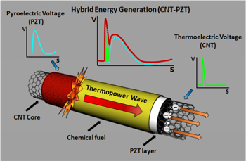
Figure 1. Schematic diagram of pyroelectric and thermoelectric hybrid energy generation from TWs in CNT–PZT fuel composites. Thermally excited charge carriers are transported through the CNT array, while the PZT layer generates the pyroelectric voltage during the heating and cooling processes of the TWs.
Download figure:
Standard image High-resolution image2. Materials and methods
2.1. Synthesis of vertically aligned multi-walled CNTs
The vertically aligned multi-walled carbon nanotubes (VAMWCNTs) were synthesized as the core material for TWs using the thermal chemical vapor deposition (TCVD) method. 10 nm-thick Al2O3 and 1 nm-thick Fe layers were deposited on a predesigned silicon wafer by sputtering and e-beam evaporation, respectively. The catalyst layer on the silicon wafer was placed in a 4 in quartz tube, and Ar gas filled the whole volume of the quartz tube to prevent oxidation of carbon during the high-temperature processes. The successive injection of H2 gas induced the transformation of the Fe layer to Fe nanoparticles as roots of the individual MWCNTs. A hot tungsten filament at the entrance of the quartz tube promoted the decomposition of the hydrocarbon gas (ethylene), as well as the growth rate of the MWCNTs. The MWCNTs were mainly synthesized at 750 °C for 2 h, and the resulting length of the VAMWCNTs was in the range 5–9 mm.
2.2. Fabrication of multiple core–shell composites of CNT–PZT chemical fuel
Solution processing at room temperature was used to fabricate the multiple core–shell composites of the CNT–PZT chemical fuel. PZT was purchased from HIGGSLAB. Co. Ltd The PZT dissolved in acetonitrile was injected into the porous structures of VAMWCNTs. After complete evaporation of the acetonitrile, 2–5 μm PZT particles remained on the surface of the VAMWCNTS, which formed the core–shell composites of CNT–PZT. A hybrid composition of CNT–PZT structures and chemical fuels was prepared using the wet impregnation method. The hybrid mixture of picric acid (2,4,6–trinitrophenol) and sodium azide (NaN3) was used as solidified fuel for TWs.
2.3. Characterization of CNT–PZT composites (Raman and SEM)
The CNT–PZT composites were analyzed to observe the decoration of PZTs on the surface of the CNTs and the morphological structures of the composites before and after the application of TWs using scanning electron microscopy (SEM, FEI Quanta 250 FEG) and Raman spectra (Horiba Jobin Yvon/ LabRAM ARAMIS IR2 spectrometer). After the application of the TWs, the multiple core–shell composites were physically dispersed to observe the inner defective structures of CNTs, as well as the aggregation of PZTs.
2.4. Ignition method for initiating TWs
The multiple core–shell composites of CNT–PZT fuels were placed on a glass and attached to two copper electrodes at both sides using silver paste. Chemical fuels, mixtures of picric acid, and sodium azide on the surface of CNT–PZT composites were combusted from one edge by a joule-heated nickel-chrome wire. Picric acid was the primary fuel for a self-propagating combustion through the aligned CNTs, while sodium azide was the promoter to lower the activation energy for ignition. A DC supply (MASTECH HY3020) applied 7–9 V to the 10 cm nickel-chrome wire, increasing the wire temperature to over 300 °C, which was the ignition temperature of fuel mixtures. After the initiation of self-propagating combustion along the aligned CNTs, the nickel-chrome wire was detached from the composites.
2.5. Measurement of TWs
The major factors of TWs, i.e. the voltage generation, reaction velocity of fuels, and dynamic temperature changes were measured using a predesigned experimental setup. An oscilloscope (TEKTRONIX DPO2004B) recorded the voltage signal generated in TWs in real time. At the same time, the reaction velocity and overall aspects of combustion in TWs were obtained using a high-speed camera system with a macrolens at 5000 frames s−1 (Nikon Phantom V7.3-8 GB color camera, macrolens 105 mm, f/2, 8D).
3. Results and discussion
3.1. Propagation of combustion in CNT and CNT–PZT composites
As a base core material for TWs, VAMWCNTs were synthesized using the TCVD method. The synthesized array of MWCNTs was detached from a silicon wafer substrate, and the cross-sectional area of the CNT array was controlled through a postprocessing treatment. It is generally known that a core material with high aspect ratio is suitable for energy generation using TWs. The thin strip of MWCNTs with a high aspect ratio was detached from the VAMWNCT forest, while maintaining the well-aligned structures of CNTs, as shown in figure 2(a). For confirmation of dual-energy generation using thermoelectrics and pyroelectrics, two experimental platforms of CNT fuel composites with and without the inner PZT layer were fabricated, as described in section 2. Briefly, PZT dissolved in acetonitrile was prepared and injected into the porous structures in CNTs. After complete evaporation of the solvent, the core–shell structures of CNTs and PZTs were obtained, as shown in figure 2(b). SEM images of the inner structures of CNT–PZT composites confirmed that the microparticles of PZTs were stuck to the CNTs. The coating of chemical fuels for CNT and CNT–PZT composites was conducted using the wet impregnation process of mixtures of picric acid and sodium azide as a primary fuel and a promoter for ignition, respectively. The visible colors of CNT and CNT–PZT composites were dark–black and white, respectively, while the fuel coatings showed a yellow color (figures 2(a) and (b)).

Figure 2. CNT fuel composites and CNT–PZT fuel composites. (a) CNT strip synthesized using the TCVD process (blue arrow), CNT fuel composite after the wet impregnation process of fuels (red arrow), and SEM image of the aligned CNTs after TCVD. (b) CNT–PZT composites fabricated by injection of PZT-dispersed solution (blue arrow), CNT–PZT fuel composite after the wet impregnation process of fuels, and SEM image of CNT–PZT composites.
Download figure:
Standard image High-resolution imageRepresentative TWs of the CNT fuel composite and CNT–PZT fuel composite are shown in figures 3(a) and (b), respectively. Ignition by the joule-heated nickel-chrome wire at one edge initiated self-propagating combustion waves for both composites, while the high-speed microscopy setup recorded the real-time propagation of the chemical reaction. The duration of the combustion waves in a CNT fuel composite and CNT–PZT fuel composite were 6.3 ms and 10.7 ms, respectively, while the heating time for the entire CNTs and CNT–PZTs exposed to combustion were approximately 480 ms and 570 ms (figures 3(a) and (b)), respectively. The average reaction velocities of self-propagating combustion waves in both cases are summarized in figure 3(c). The reaction velocity of CNT–PZT fuel composites was lower than that of CNT only fuel composites. The addition of PZTs in the multiple core–shell structures, as well as the addition of thermal contact resistances at the boundaries of the CNTs and PZTs, might interrupt the accelerated combustion waves owing to the low thermal conductivity of the PZTs. The thermal conductivity of MWCNTs is theoretically 600 ± 100 W m−1 K−1 at room temperature, whereas the thermal conductivity of PZTs is 1.38 ± 0.10 W m−1 K−1 [25]. Such a difference would affect the deceleration of the reaction velocity in CNT–PZT fuel composites. In previous studies, the increase in the propagation velocity in combustion generally amplifies the voltage magnitude from TWs [26]. In this study, there was no critical difference in the reaction velocities between CNT fuel composites and CNT–PZT fuel composites, although the reaction velocity of CNT–PZT fuel composites was relatively slower than that of CNT fuel composites. In this respect, the intrinsic voltage generation via thermoelectrics from TWs in CNT fuel composites would be slightly greater than that in CNT–PZT fuel composites. However, in this range of reaction velocities and thermal diffusion length of the CNT array, the extreme temperature gradient along the aligned direction of CNTs existed during the propagation of the chemical reaction in both cases, because the reaction propagation was too short to cool the core materials that were exposed to combustion waves. After completion of the propagation of combustion waves, the core materials, i.e. CNT or CNT–PZT composites were in the same sequential heating and cooling processes as bulk materials, and the temperature gradient along the aligned direction quickly disappeared owing to fast thermal transport through the CNT array. It is known that the thermal conductivity of the aligned CNTs reaches 600 ± 100 W m−1 K−1, which is sufficient to achieve thermal equilibrium in the CNT array in the composites. On the other hand, the absolute magnitude of temperature, which indicated the average number of core materials, gradually increased and decreased in the heating and cooling processes when the total duration of heating was 480 ms and 570 ms for CNT and CNT–PZT composites, respectively. After the heating process, CNT and CNT–PZT composites were cooled in ambient conditions, which induced the negative potential of the voltage signals by pyroelectrics. The heating durations of both cases were two orders of magnitude greater than that of the propagation of combustion. Such an increase in average temperatures in core materials would be a source of pyroelectric energy generation, especially for CNT–PZT composites.

Figure 3. Combustion waves in TWs. Propagation of combustion in (a) CNT fuel composites and (b) CNT–PZT fuel composites. (c) Reaction velocities in CNT fuel composites and CNT–PZT fuel composites.
Download figure:
Standard image High-resolution image3.2. Thermoelectric–pyroelectric hybrid energy generation from TWs
The synchronized voltage generation confirms the energy generation by the dual mechanism from CNT–PZT composites (figure 4). The TWs in the CNT fuel composites showed a sharp single-peak voltage signal in a short duration (figure 4(a)). This indicated that the charge carrier transport through the CNT array induced by the temperature gradient along the aligned direction only produces electrical energy from TWs. On the other hand, CNT–PZT fuel composites formed dual peaks, which were composed of a sharp peak for a short duration followed by wide peak for a long duration (figure 4(b)). As explained in the analyses of figure 3, the heating process for entire core materials after the completion of propagation of combustion waves enabled the additional energy generation by means of pyroelectrics from PZTs. The voltage generated from TWs in previous studies have mostly depended on the thermoelectrics of core materials, such as metal oxides, bismuth or antimony-based materials, and CNTs, because the propagation of the high-temperature regime in the reaction front accelerates the charge carriers, which are excited by the thermal energy gradient along the propagating direction of combustion [27]. The addition of PZTs, one of the most widely used pyroelectric materials, could utilize the gradual temperature increase in the heating transfer along the orthogonal direction through the bulk core materials after completion of combustion. This means that the unused thermal energy in previous studies can be utilized in CNT–PZT composites, based on dual-energy generation using thermoelectrics and pyroelectrics. In fact PZTs have two major mechanisms to produce electrical energy, i.e. piezoelectrics and pyroelectrics, in response to dynamic change in mechanical or thermal energy [28]. In TWs, the increase in temperature of the bulk core materials induces a change in the atomic structures in the crystals of the PZTs and the synchronized polarization, which creates the voltage generation across the crystal, as shown in figure 4(b). In addition to the appearance of the second peak, the voltage magnitude in the first sharp peak was also enhanced in the CNT–PZT fuel composites, as shown in figure 4(c). The average and maximum voltages in CNT fuel composites were 270 mV and 500 mV, respectively. By contrast, the CNT–PZT fuel composites produced 403 mV and 1100 mV as the average and maximum voltages, respectively. These results indicate that the pyroelectric energy generated by PZTs might contribute to amplifying the voltage generation in the first sharp peak as well as the generation of the second wide peak. When combustion waves are propagated along the aligned direction of the CNTs, the exothermic energy at the reaction zone is immediately transferred to the neighboring core materials, CNTs or CNT–PZTs. The supplied heat to the neighboring core materials might induce a rapid increase of the average temperature, which could stimulate the PZTs to generate electrical energy by pyroelectrics, in addition to charge carrier movements along the aligned direction by thermoelectrics in the longer duration of the propagation of combustion waves. Furthermore, it should be noted that even though the reaction velocity of CNT fuel composites was slightly higher than that of CNT–PZT fuel composites, as shown in figure 3(c), the voltage magnitude for CNT–PZT fuel composites was much higher than that for CNT fuel composites. The previous theory about TWs states that charge carriers are entrained in the thermal energy of reaction waves, similar to the trigger of voltage generation [10]. This implies that the voltage generation in TWs would only be induced by thermally excited charge carriers. However, by inserting the PZTs, the voltage generation could be amplified regardless of charge carriers in the CNT array, because the pyroelectric energy generation in PZTs acts like a battery in the electric circuits of the composites and enables the increase in peak voltage. In comparison with previous works using CNTs for TWs, the average peak and duration of voltage were highly enhanced, by a factor of 2 and 60 times. The CNTs without PZTs showed 157 mV and 10 ms [19], whereas the addition of PZTs significantly amplified the overall energy generation; 403 mV and 612 ms for the average peak and duration of voltage, respectively.

Figure 4. Hybrid energy generation from TWs. Representative voltage signals from TWs (a) in CNT fuel composites and (b) in CNT–PZT fuel composites. Blue and red arrows indicate the first sharp peak and the second wide peak of voltage signals, respectively. (c) Comparison of average peak voltage in the first sharp peaks from TWs in CNT fuel composites and CNT–PZT fuel composites. (d) Real-time distribution (top) and first derivative (bottom) of temperature change in the PZT layer induced by combustion waves. (e) Corresponding voltage signal with the first derivative of temperature change (top) and extended voltage signal during heating (bottom) of CNT–PZT composites induced by TWs.
Download figure:
Standard image High-resolution imageThe comparison of temperature change in a PZT layer and the whole voltage signal in heating and cooling processes elucidated the synchronized energy generation with pyroelectrics from TWs. The real-time distribution and the calculated first derivative of temperature in a PZT layer were shown in figure 4(d) when the combustion of chemical fuel supplied the thermal energy at the initial stage. Although the propagation of combustion was finished in 10 ms, as described in the above section, the heating process of a PZT layer continued for up to 1000 ms, which was in a similar range to the voltage signal from TWs in CNT–PZT composites in figure 4(b). After the heating process, the PZT layer was in the cooling process for several seconds, which might induce a negative potential of voltage signal. The first derivative of temperature changes in figure 4(d) provided the information that there had to be a positive potential in the heating process and a negative potential in the cooling process. The full voltage signal from a CNT–PZT composite during the heating and cooling processes exactly confirmed the energy generation from pyroelectrics in TWs (figure 4(e)). During the heating process, for 1000 ms, the voltage signal was identical to the first derivative in figure 4(d), while the cooling process formed a negative potential, as was expected. Furthermore, the extended voltage signal clearly showed that the two voltage peaks from thermoelectrics and pyroelectrics were obtained with durations of 10 ms and 1000 ms, respectively.
3.3. Superposition of voltage signals of thermoelectrics and pyrolectrics in TWs
To investigate the superposition of voltage generations from thermoelectrics and pyroelectrics in TWs, control experiments using CNT fuel composites were conducted under a 500 mV voltage provided by a DC power supply. In this experiment, almost 0 mV was initially measured before the application of TWs, in spite of applying 500 mV to CNT fuel composites, because the electrical resistance of the test sample was relatively higher owing to the high resistance of the chemical fuels between the CNTs and copper electrodes. During the propagation of the TWs, the chemical fuels were consumed and the CNTs made direct connection with the copper electrodes. At this time, similar to the voltage generation from pyroelectrics, 500 mV was supplied to the CNT array, while the voltage generation concomitantly occurred by thermoelectrics from the TWs. As shown in figure 5(a), the supply of 500 mV DC voltage at the starting point of the TWs for CNT fuel composites without PZTs could result in voltage signals similar to those for CNT–PZT fuel composites, which resulted in both thermoelectric and pyroelectric energy generation. For the superposition of energy generation, the final voltage magnitude should be identical to the summation of the voltage generations from two different sources in the hybrid composites. The voltage increases under the 500 mV input condition for CNT fuel composites are summarized in figure 5(b). The average values of peak voltage under 500 mV produced 923 mV, whereas TWs without the additional voltage input only generated 270 mV. The source of voltage increase was obviously derived from the additional input voltage from the DC power supply. This indicates that the voltage generation from pyroelectrics in PZTs could highly amplify the voltage peaks in the same way with power suppliers.
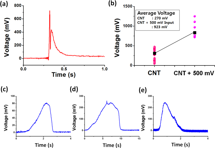
Figure 5. Experimental verification for superposition of voltage generation and pyroelectric energy generation in a PZT layer. (a) Voltage signal from TWs in CNT fuel composites under a 500 mV applied voltage from a DC power supply. (b) Comparison of peak voltage from TWs in CNT fuel composites with and without 500 mV applied voltage. Pyroelectric voltage generation on the PZT layer only during heating and cooling processes induced by (c) 1000 mW laser irradiation, (d) butane gas torch, and (e) combustion of chemical fuels.
Download figure:
Standard image High-resolution imageTo improve the understanding of energy generation from PZTs, controlled thermal energy was applied to only the PZT layer to investigate the quantitative information of pyroelectrics from PZTs in the composites during the heating and cooling processes. Three different heating sources, i.e. a 1000 mW laser, a butane gas torch, and fuel combustion, were used as suppliers of intensive thermal energy. First, the 1000 mW laser heating induced a gradual increase of voltage up to 80 mV during heating, while the disappearance of voltage signal occurred in the cooling process (figure 5(c)). Because the laser heating might need a moderate time to reach equilibrium between heating and cooling, a gradual increase occurred. Heating by butane gas torch presented similar trends as the laser heating, although the maximum peak voltage (∼240 mV) was higher than that of laser heating (figure 5(d)). Because the thermal energy from the gas torch was considerably higher than that of laser heating, the equilibrium temperature between heating and cooling was higher than that of laser heating, which resulted in an increase in voltage. However, it still showed a gradual increase of voltage during heating. On the other hand, the fuel combustion surrounding PZTs without the core CNT array presented an identical shape with a second voltage peak from TWs, which had a rapid increase in voltage on heating, and then a gradual decrease in voltage (figure 5(e)). The above control experiments strongly support the fact that the origin of the second voltage peak, described in figure 4(b), was due to pyroelectric energy generation induced by the fuel combustion in CNT–PZT fuel composites.
A comparison of the first sharp peak of short duration and the following wide peak of long duration reveals the proportion of the energy generation from thermoelectrics and pyroelectrics (figure 6). The average voltage of the first sharp peak and second wide peak was 403 mV and 141 mV (figure 6(a)), respectively, while the duration of the voltage signal of the first sharp peak and second wide peak was 9.76 ms and 612.2 ms (figure 6(b)), respectively. The voltage signal in the first sharp peak showed three to four times greater maximum values than that of the second wide peak, and the first sharp peak presented a much shorter duration of voltage signal than that of the second wide peak. The first sharp peak voltage generation was attributed to both thermoelectrics and pyroelectrics in CNTs and PZTs induced by combustion waves. The TWs in CNT–PZT fuel composites enabled the thermally excited charge carrier to be transported through the CNTs, driven by the temperature gradient at the starting and ending positions of combustion. At the same time, the rapid increase in the overall temperature in PZTs also added to the pyroelectric energy generation as the superposition of energy generation by two different mechanisms. Moreover, the voltage duration was in a similar range to the propagating time of combustion. On the other hand, the second wide peak voltage was produced by the pyroelectrics in PZTs only, during the relatively gradual heating process along the orthogonal direction through PZTs after the propagation of combustion. Owing to fast thermal diffusion inside CNTs, the temperature gradient at both sides rapidly disappeared, and thermoelectric energy generation could not occur in the gradual heating process. Meanwhile, the heat transfer through PZTs and CNTs along the orthogonal direction was a relatively slower process, and the gradual increase in temperature in the bulk materials counted on the energy generation from TWs.

Figure 6. Comparison of voltage generation in the first sharp peak and the second wide peak from TWs in CNT–PZT fuel composites. (a) Average peak voltages and (b) duration of TWs in the first sharp peak and the second wide peak.
Download figure:
Standard image High-resolution image3.4. Structures and reusability of CNT–PZT composites in repetitive TWs
The CNT array and PZTs before and after the application of TWs were characterized by SEM images and Raman spectra in order to elucidate the effects of combustion on the core materials and the corresponding principles of energy generation (figure 7). First, the CNT array maintained its aligned structure, whereas regimes damaged by the high-temperature reaction were observed, as shown in figures 7(a) and (b). The PZTs presented similar physical changes to CNTs. Before the application of TWs, the PZT particles in cubic shapes were attached to the CNT array (figure 7(c)). After the application of TWs, the dimensions of the PZT particles did not change; however, aggregation among PZT particles was clearly observed (figure 7(d)) owing to their exposure to high-temperature combustion, which was close to 800 °C [29, 30]. Although the SEM images provided the physical shapes or structures of CNTs and PZTs, further investigation is needed to confirm the chemical interaction inside the CNT–PZT fuel composites with TWs. Raman spectra were used to determine any chemical interaction during the TW propagation based on atomic bonding changes. The specific peaks of the Raman spectra from the as-synthesized CNTs (figure 7(e)) and the PZTs (figure 7(f)) before the application of TWs were compared with the specific peaks from CNT–PZT hybrid structures in figure 7(g). First, the specific peaks of CNTs in the Raman spectra after the application of TWs were nearly identical to those of as-synthesized CNTs by TCVD, as shown in figures 7(e) and (g). This indicates that the CNT chemically maintained its original properties after the application of TWs, except for the physically damaged regimes, as shown in figure 7(b). Moreover, the wave numbers of the PZTs at 250 cm−1, 500 cm−1, and 720 cm−1 were clearly maintained before and after the application of TWs. Therefore, the PZTs were not chemically changed, except for physical aggregation, as shown in figure 7(d). In fact, PZT-based pyroelectric devices should undergo a calcination process for the deformation of PZTO3 (P(Z0.5–T0.5)O3) to obtain a perovskite crystal structure [31]. Normally, the calcination process is conducted in a high-temperature furnace at 600 °C [32]. However, for the experiments of TWs in this study, although the PZTs in hybrid composites did not undergo the calcination process, pyroelectric generation was clearly obtained. It should be noted that the high-temperature reactions in TWs might instantly induce calcination on PZT particles in the CNT–PZT fuel composites and enable pyroelectric energy generation without an annealing process.

Figure 7. Characterization of CNT–PZT composites before and after application of TWs. SEM images of CNT–PZT composites (a) before and (b) after the application of TWs. SEM images of PZT particles attached to CNTs (c) before and (d) after the application of TWs. Raman spectra of (e) the CNT array and (f) PZT particles before the application of TWs, and (g) CNT–PZT composites after the application of TWs.
Download figure:
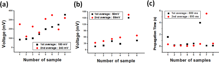
Standard image High-resolution imageThe reusability of CNT–PZT composites was investigated by evaluating the voltage signals induced by the second set of TWs (figure 8). In this experiment, the energy generation from the first set of TWs was performed on the CNT–PZT composite once, and the remaining CNT–PZT composite was collected to coat the chemical fuel for the second set of TWs. In the reformulated CNT–PZT fuel composite, the energy generation from the second set of TWs was conducted to evaluate the stability of composites in repetitive TWs. In the case of the first sharp peak, the maximum voltage in the first TW and the second TW were 180 mV and 248 mV (figure 8(a)), respectively. The amplification of voltage magnitude is due to the presence of a defective regime in the CNT array, as shown in figure 7(b). In the propagation of combustion waves, the increase in electrical resistance in the core materials generally leads to the amplification of voltage signals. In these composites, the damaged regime of the CNT array by the first TW increased the electrical resistance, which resulted in voltage amplification. In the case of the second wide peak, the maximum voltage in the first TW and the second TW was 50 mV and 59 mV (figure 8(b)), respectively. As shown in figure 7(d), apart from aggregation, there were no critical changes in the PZTs. Therefore, the voltage generation did not significantly change for the second wide peak. Furthermore, the voltage signals in the first TW and second TW had almost the same duration, which indicates a similar reaction velocity. These experimental data confirm that CNT–PZT composites can be reused for multiple TWs to produce more energy.
Figure 8. Energy generation from repetitive TWs in CNT–PZT core–shell composites. (a) Average first sharp peak voltages, (b) average second wide peak voltages, and (c) average propagating times of combustion at the first TW and second TW.
Download figure:
Standard image High-resolution image
4. Conclusion
In summary, we demonstrated the enhancement of thermoelectric and pyroelectric hybrid energy generation from TWs using CNT–PZT fuel composites. Moreover, the reusability of the composites was thoroughly verified. The temperature gradient in the CNT array produced an accelerated charge carrier to be transported along the aligned direction, which defined the thermoelectric energy generation, while the gradual increase in the temperature by the heat transfer along the orthogonal direction through PZT-CNTs in the TWs induced polarization changes in the crystals, which defined the pyroelectric energy generation. The peak voltages and duration of energy generation were highly enhanced by the hybrid energy generation. The advanced TWs obtained by hybrid energy generation can facilitate further development of TW-based operating devices and an understanding of the transport phenomena, driven by the combustion at the interface of the micro-nanostructured materials. Furthermore, the major achievement in this study paves the way for the application of TWs as a new type of portable energy source with high power density.
Acknowledgments
This work was supported by the Basic Science Research Program through the National Research Foundation of Korea (NRF), which is funded by the Ministry of Education (NRF-2015R1D1A1A01059274). The authors gratefully acknowledge the financial support provided by the Defense Acquisition Program Administration and the Agency for Defense Development under contract UD150032GD.
Author contributions
All the authors contributed to the manuscript. Furthermore, all the authors participated in the design of the experiments and in the data analysis and have approved the final version of the manuscript.