
Abstract
This paper presents a methodology to effectively harness low-frequency broadband rotational energy using coupled electromechanical nonlinearities. This design integrates bi-stability and a synchronized switch harvesting on inductor (SSHI) circuit into a frequency up-converting harvester (FRUCH). The bistable behavior enables improved output power due to the increased vibration amplitude under the same input plucking force. The SSHI circuit exhibits enhanced conversion capability, contributing higher electrical damping which is ideal for FRUCHs to alleviate output power fluctuation at high frequencies. To study the coupled nonlinear dynamics from both the mechanical (bi-stability) and electrical (SSHI) sides, a system-level theoretical model is, for the first time, established and numerically solved using Matlab/Simulink. System behaviors, which would not be able to obtain using circuit simulation methods, are studied for different operating frequencies and load resistances. To validate the theoretical analysis, this harvester was implemented and tested experimentally. A close match was obtained. From the experimental results, an enhanced output power (up to 525%), over a broad frequency range, was realized, compared to that of a harvester with neither bi-stability nor SSHI circuits.
Export citation and abstract BibTeX RIS
1. Introduction
Kinetic energy harvesting, as a technology to convert ambient motion into electricity for low-power electronics, has been extensively investigated in the last decade [1–4]. Different conversion mechanisms, including piezoelectric, electromagnetic, electrostatic and triboelectric transduction, have been extensively adopted and investigated [5, 6]. Among these methods, piezoelectric conversion has been widely used due to its simplicity in structure and compatibility with micro-fabrication [7, 8]. A cantilever beam with a proof mass under base excitation is the general paradigm for piezoelectric energy harvesters (PEHs), but this design is ineffective for harnessing low-frequency and broadband kinetic energy sources due to its linear characteristic [9].
Frequency up-converting harvesters (FRUCH) provide a practical solution by converting random and low-frequency motion into high-frequency transducer resonance [10]. Direct (impact) [11–13] or indirect (magnetic) [14–16] plucking mechanisms are generally adopted to excite the harvesters by applying plucking force at the transducers' free end. After plucking, the transducers vibrate freely at resonance. Impact motions are widely distributed or easily acquirable from the ambient environment, such as from human motion [17, 18], heartbeat [19] or machinery rotation [20, 21]. One example is a miniaturized turbine with piezoelectric transduction and frequency up-conversion for airflow energy harvesting in [22]. Airflow is converted into low-frequency rotation by the turbine; a piezoelectric beam is plucked by the magnetic force between a driving magnet on the turbine rotor and a tip magnet at the beam's free end. However, FRUCHs generally face a critical issue of output power fluctuation when the plucking frequency fp approaches the resonant frequency fr of the transducers (fp < fr). This is due to the fact that when the plucking frequency is increased, the time for the transducer's free vibration after each plucking is reduced. The vibrating beam can then interfere with the following plucking force, resulting in output power fluctuation. Increasing the harvester's damping from either the mechanical side (controlled ring-down vibration) or the electrical side (increased electrical damping force by the piezoelectric conversion) was suggested to be a solution [21].
Bi-stability is a way to enhance the output power when harvesters operate in a high energy orbit (periodic double-well mode) that allows the beam to exhibit improved displacement and output voltage [23, 24] and effectively operate under random vibrations [25]. This improved energy converting capability results in an increased electrical damping force applied on the vibrating beam; this could be a potential solution to not only reduce the output fluctuation, but also to improve the output. Many efforts have been made on bistable harvesters to improve the performance in improving output power [26, 27], broadening operating bandwidth [28], lowering the input excitation requirement [29]. Wang et al developed an elastic magnifier-assisted bistable PEH by mounting the harvester on a vibration base via an elastic magnifier [30]. By changing the ratio between the harvester mass and the magnifier stiffness, this system exhibited a wider operating bandwidth and higher output power than a bistable harvester without the magnifier. Nguyen et al introduced an auxiliary magnet oscillator to dynamically adjust the potential shape of a bistable harvester [31]. Zhou and Zuo studied the nonlinear dynamics of asymmetric tristable energy harvesters and provided a way to enhance harvester performance under different levels of excitation [32]. Zhang et al used stochastic resonance in a piezoelectric energy harvesting from auto-mobile wheel motion under gravity and random vibrations due to vehicle movement [33]. Yang et al proposed a compressive-mode harvester synthesizing the merits of the force amplification effect of a flexural motion and the dynamic properties of elastic beams [34]. We previously integrated bi-stability into a rotating FRUCH to reduce the power fluctuation using the inter-well to intra-well motion transition after each plucking; improved output power over a wide bandwidth was obtained [35].
Effective power management circuits can also improve the energy conversion capability from kinetic energy to electricity, which also means that improved electrical damping is applied on the mechanical vibration. Synchronized switch harvesting on inductor (SSHI) is a technique developed by Guyomar et al [36]. Many developments on SSHI circuits, including self-powered [37, 38], high-efficiency [39] and cold-startup [40] circuits, have been developed in the past decade. One common operation condition for these circuits is that an inertial energy harvester vibrates under the sine-form base excitation [41, 42]. When such harvesters (circuits) operate with broadband, stochastic motion [37], appropriate switching instances are difficult to determine reliably. The variation in width and amplitude of peaks and the presence of abundant local extrema lead to unnecessary switching events that consume net power, counteracting the advantage of SSHI circuits [43]. Compared to harvesters under base excitation, FRUCHs, which convert random, low-frequency motion into uniform, single-frequency output waveforms, are ideal for SSHI circuits. Furthermore, this SSHI method exhibits an enhanced harvesting capability compared to conventional full-bridge rectification circuits, applying stronger electrical damping forces on piezoelectric transducers' mechanical vibration. This enhanced electrical damping can be an effective way to reduce the power fluctuation issue at high frequencies; this effect has been investigated and confirmed in our previous work in [44], in which the SSHI technique was combined with a FRUCH. The power fluctuation issue was reduced at high frequencies, but the output power enhancement allowed for further enhancement.
In this paper, bi-stability and a SSHI circuit are integrated in a FRUCH to employ their advantages to address the power fluctuation issue and to enhance the output power over a broader operating frequency range at low frequencies. The main challenge lies in establishing the theoretical model to study the coupled nonlinear behaviors from both bi-stability and the SSHI circuit in a holistic manner. In our previous work in [35], only the mechanical nonlinearity from bi-stability was investigated without considering the influence of power management circuits. Our work in [44] combined a FRUCH with a SSHI circuit, but there is no mechanical nonlinearity in that harvester. In the literature, bi-stability and SSHI circuits are generally studied in a decoupled manner, neglecting either mechanical [45] or electrical dynamics [46–48]. It is, therefore, necessary to establish a comprehensive model to study the dynamics as a whole system, as the overall performance is determined by both the mechanical and the electrical nonlinearity.
In order to study the nonlinear dynamics in a coupled manner, a unique theoretical model and a numerical solution are proposed to investigate the coupled mechanical and electric nonlinearity, which to the authors' knowledge has never been published in the literature. The dynamics of different configurations, which are impossible to obtain using circuit simulation methods, are investigated numerically for different operational frequencies and load resistances. An experimental study was then conducted to validate the theoretical results. Improved output power over a wide bandwidth was obtained from the FRUCH with bi-stability and a SSHI circuit.
2. Harvester design and theoretical modeling
2.1. Bistable frequency up-converting harvester
Figure 1(a) depicts the design of the bistable frequency up-converting harvester (Bi-FRUCH). The piezoelectric beam is magnetically plucked by the driving magnet at a frequency much lower than the transducer's resonant frequency (e.g. fp < fr/10). This magnet can be mounted on any motion hosts, such as a device using the relative motion between upper and lower legs for human motion harvesting [49] or a micro-turbine for airflow energy harvesting [50]. The beam can be plucked at any low and random frequencies. After each plucking, the beam oscillates freely at resonance in the y-axis as shown in figure 1(a). The detailed bending direction and plucking force components are shown in figure A1. The voltage waveform is single-frequency and uniform, even when the excitation frequency is random or broadband. This stabilized waveform is ideal for SSHI circuits to determine proper switching events.
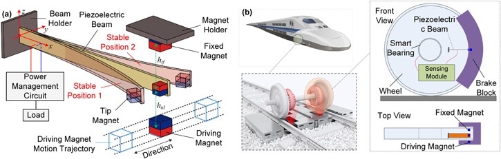
Figure 1. Harvester design and potential application illustration. (a) Schematic of the bistable frequency up-converting harvester with a power management circuit. The bent beams illustrate the equilibrium states. The blue and red blocks on the magnets indicate the magnetization direction. (b) Illustration of the application of a harvester for a self-powered smart bearing in train wheels.
Download figure:
Standard image High-resolution imageBi-stability is realized by the repulsive force between the tip magnet and the fixed magnet. When the beam oscillates between the two equilibrium positions, larger beam displacement and velocity can be achieved. Therefore, increased output power can be realized. The key is to keep the beam oscillating between the equilibrium states. This operating mode can be maintained when the input magnetic force is large enough to conquer the potential barriers between the equilibrium states.
A potential application of this design in low-power sensing systems is illustrated in figure 1(b). This harvester is mounted between the wheel and the vehicle brake block in the same way as the arrangement in figure 1(a). The piezoelectric beam is amounted on the wheel, to convert energy from vehicle motion; and the converted energy is used to power a sensing unit for bearings in vehicle wheels. A self-power smart bearing can be implemented with such an energy harvester.
For the bistable beam, the potential energy stored is the sum of the elastic potential energy (Ue) of the beam and the magnetic potential energy (Um) of the tip magnet. Therefore

In order to calculate the magnetic potential energy stored in the magnets, a theoretical model proposed by Akoun and Yonnet is adopted [51]. The potential energy stored by the tip magnet can be expressed as
where J and  are the magnetization, μ0 is the magnetic constant, and ψ is a function of the magnet dimensions and their relative positions in three axes for the magnetic potential calculation. These lengths, Uij, Vkl and Wpq, correspond to the distance between the cube corners and their projections on the axes. The parameters i, j, k, l, p and q, are equal to 0 or 1 according to the specific corner. More details about the calculation can be found in [51, 52].
The magnetic force between two magnets in the y-axis can thus be calculated using
where  means the force applied on the tip magnet by one source (driving magnet or fixed magnet) in the y-axis and ϕy is the function of the magnet dimensions and their relative positions in three axes for the magnetic force calculation. The force diagram for calculation is shown in figure A1.
The elastic potential of the piezoelectric beam under bending motion can be given by

where YI is the combined bending stiffness of a series-connected bimorph with piezoelectric material fully covered on the both surfaces of a substrate layer, υ(x, t) is the beam transverse deformation. The beam deformation is calculated using the distributed parameter model built by Erturk and Inman [53]. In our work, adaptation has been made for the bistable FRUCH model. The driving magnetic force  and the force for bi-stability
  in the beam bending direction (y-axis), are considered as external forces applied at the free end of the piezoelectric beam, and the tip magnet is regarded as a proof mass. The beam dynamics can be written as
where csI is the internal damping, ca is the viscous deformation damping, m is the mass per unit length of the beam, δ(x) is the Dirac delta function, ϑ is the piezoelectric coupling term in physical coordinates and V(t) is the voltage on the beam. The beam displacement υ(x, t) can be expressed as a convergent series of the eigenfunctions:

where ϕr(x) and ηr(t) are the mass normalized eigenfunction and the modal mechanical coordinate of the cantilever beam with respect to its rth mode shape. The mechanical equation can be further reduced to the modal coordinate by substituting equations (6) into (5), multiplying ϕr(L) and integrating over the beam length:
where ζr is the modal damping ratio of the rth mode shape, ϑr is the electromechanical coupling term, and ωr is the effective undamped modal frequency. The modal damping ratios ζr are normally obtained experimentally. The detailed deduction process from equations (5) to (7) can be found in [53]. The governing equation from the electrical side can be expressed as

where Cp is the piezoelectric beam's capacitance and Il is the current passing through the subsequent power management circuit. The electromechanical dynamics of the harvester can be solved from equations (7) and (8). It is worth mentioning that as FRUCHs generally operate at their resonant frequency, and the fundamental vibration mode is dominant, only the fundamental vibration mode (r = 1) is considered in the following calculation for simplicity.
2.2. SSHI interface circuit
The operation principle of a SSHI circuit with the bistable harvester is illustrated in figure 2. For SSHI interface circuits, there are parallel and series types [54, 55] which are all compatible to this bistable harvester. Here, a parallel SSHI (P-SSHI) circuit is adopted, as shown in figure 2(f). Compared to a standard bridge rectifier circuit (figure 2(a)), a switch S and an inductor L are connected in parallel to the bridge rectifier. The switch status is determined by the beam displacement. When beam displacement peaks occur, the switch is closed for a short time frame ( , much shorter than the beam vibration period), and the voltage on the beam is reversed from Vc (or −Vc) to −Vm (or Vm), as shown in figure 2(j). Then the switch is open, and the voltage on the piezoelectric beam builds up from Vm. A smooth capacitor Cs is adopted for both circuits (a) and (f). This capacitor also serves as the energy storage, and is usually selected much larger than the internal capacitance of the piezoelectric beam Cp. Therefore, the voltage Vc across Cs can be regarded constant in the steady state.

Figure 2. Operation principle of the SSHI circuit with a bistable frequency up-converting harvester (Bi-FRUCH) in comparison with a frequency up-converting harvester (FRUCH) with neither bi-stability nor SSHI. (a) and (f) Schematic of standard and SSHI circuit; (b), (c), (g) and (h) beam tip displacement and output voltage; (d), (e), (i) and (j) enlarged view of (b), (c), (g) and (h) respectively.
Download figure:
Standard image High-resolution imageFor the bistable harvester (Bi-FRUCH), in each plucking cycle (driving magnet motion cycle), the harvester is first plucked to oscillate between two stable positions for a few cycles (as shown in figure 2(g)), before the energy stored on the beam is lower than the potential barrier. Then the harvester settles in one of the stable positions with low vibration amplitude and output voltage. This enhanced output voltage during the double-well oscillation is ideal for the SSHI circuit to exhibit a high converting performance, and the reduced vibration amplitude in the single-well oscillation avoids the interference between the vibrating beam and the subsequent driving magnet force.
For FRUCHs, output power fluctuation at high frequencies (approaching the beam's resonance frequency) due to the above-mentioned interference is a significant issue that limits the output power and operating bandwidth [21]. Higher electrical damping is suggested to be a potential solution to dampen the beam vibration more quickly in one plucking cycle. SSHI circuits exhibit an improved power harvesting capability compared to conventional rectifier circuits, which means higher electrical damping is applied. Therefore, the combination of bi-stability and SSHI circuits in FRUCHs is beneficial not only to improve the output power, but also to reduce power fluctuation issue over a broader operation frequency bandwidth. The power fluctuation issue will be discussed with more details in the following sections.
In one driving magnet plucking cycle, the beam oscillation of a Bi-FRUCH in the steady state can be divided into three stages, as shown in figure 3, including the initial energy injection stage, beam double-well oscillation stage and single-well oscillation stage. In the initial energy injection stage (figure 3(a)), the driving magnet passes the tip magnet in a short time interval. The piezoelectric beam, in this process, is plucked from ① to ② by  , as shown in figure 3(a), and the initial energy Ein is injected to the beam. The injected energy can be expressed by

where Tp is the plucking cycle of the driving magnet.

Figure 3. Illustration of operation stages of the harvester. (a) Initial energy injection stage; (b) double-well oscillation; and (c) single-well oscillation. The purple background indicates the operating range of the harvester.
Download figure:
Standard image High-resolution imageThen, the driving magnet rotates away from the tip magnet. The initial energy Ein is larger than the potential barrier Eb (Ut(0)), and the beam oscillates in the double-well mode for a few cycles (②–⑥). The injected energy is consumed by the mechanical and electrical damping in this process. The double-well oscillation terminates when the energy in the beam is lower than the potential barrier Eb. This relationship can be expressed by
where n and Td are the number and period of the double-well motion, C is the mechanical damping of the system and V(t) and I(t) are the voltage and current on and passing through the piezoelectric beam, respectively.
In the double-well mode, at each displacement peak, the voltage on the beam is reversed by the inductor as shown in figure 2(f) from Vc (or −Vc) to −Vm (or Vm) (in figure 2(j)). The reversed voltage can be expressed as

where Q is the quality factor of the L–Cp loop in figure 2(f). Then the voltage builds up from Vm. When the voltage Vb on the beam is larger than the voltage on the capacitor plus the threshold voltage of diodes Vs + 2Vd, charges are transferred from the piezoelectric beam Cp to the storage capacitor Cs, and the voltage Vb on the piezoelectric beam during this process is clamped at Vc = Vs + 2Vd. Ignoring the parasitic resistance in the circuit, the voltage on the storage capacitor in the steady state can be calculated using the law of charge conversation.

where  and
and  are the initial voltage of the piezoelectric beam and the storage capacitor respectively, and
  is the stable voltage on the storage capacitor after charge transfer which can be written as

In the third stage (figure 3(c)), the beam oscillates in the single-well mode, the voltage generated on the beam is lower than the voltage on the storage capacitor. The diodes blocks the charges to transfer from the storage capacitor back to the piezoelectric beam; Cs and Cp are disconnected.
During the whole plucking cycle Tp, energy is dissipated by the load resistor Rl. The harvested energy is

The conversion efficiency can be then calculated using

In fact, different methods have been discussed in the literature for calculating the conversion efficiency, as summarized in [56], but the common definition, as shown in equation (15) is adopted here. The nonlinear behaviors from both bi-stability and the SSHI circuit are considered in the above theoretical model. Using these coupled equations, the dynamics of the FRUCH with bi-stability and the P-SSHI circuit can be solved numerically.
2.3. System-level modeling
Above subsections cover the theoretical models of both the bistable FRUCH and also an associated P-SSHI circuit. In order to calculate both the electromechanical dynamics in a coupled manner, this whole model with all the above theories is established in Matlab/Simulink, as shown in figure 4. It is worth mentioning that another software SIMetrix was previously successfully used in our work and also by Zhao et al in studying SSHI circuits combined with either a FRUCH [44] or a galloping airflow energy harvester [57] based-on an equivalent circuit model. However, issues were faced when using the equivalent circuit model to calculate the bistable dynamics. The bistable motion and force for bi-stability in equation (3) were calculated inefficiently and inaccurately. Therefore, Matlab/Simulink is adopted here.

Figure 4. Matlab/Simulink diagram of the FRUCH with bi-stability and SSHI. The whole model is divided into six blocks, including mechanical equation, magnetic force calculation, electrical equation, displacement peak detection, SSHI operation and storage capacitor voltage calculation blocks, according to the implemented functions.
Download figure:
Standard image High-resolution imageAccording to function, this whole system is divided into six blocks, including magnetic force calculation, mechanical module, electrical module, displacement peak detection, SSHI operation and storage capacitor voltage calculation blocks. In the magnetic force calculation block, two outputs are provided, including the magnetic force between the tip and driving magnets (driving force calculation) and the force between the tip and fixed magnets (bi-stability force). These calculations are based on equation (3), and more details about how to get the relative parameters in that equation can be found in [51]. As theses forces are determined by the gaps between magnets, the instantaneous beam tip displacement (dis_t in figure 4) and the position of the driving magnet (determined by clock, radius and gamma2 in figure 4) at each time step in the Simulink model is adopted as the inputs for the force calculation. The mechanical module in figure 4 is built according to equation (7). As discussed in section 2.1, only the fundamental mode of the beam is considered in this beam mechanical dynamic calculation due to the fact that the fundamental vibration mode is dominant in vibration because of the resonant vibration nature of FRUCHs. The voltage on the beam is affected by the SSHI circuit at beam displacement peaks. This is considered by using the voltage regulated by the SSHI circuit as the input to calculate the beam mechanical dynamics (V_beam in figure 4). This is one of many parts where the mechanical dynamics are coupled with the electrical dynamics.
In the electrical module, equation (8) is implemented. This module builds the connection between the beam mechanical dynamics and the SSHI circuit. The output of this module provides the beam voltage generated due to the mechanical dynamics. This voltage is used as the input for the SSHI circuit. The displacement peak detection module, as the name suggests, monitors the displacement peak, and outputs peak detection results to the SSHI operation module. When a peak is detected, the SSHI operation module will calculate the new reversed voltage on the piezoelectric beam based on equation (11). The voltage on the load Rl and the storage capacitor Cs in figure 2(f) is calculated in the storage capacitor voltage calculation module. The power consumed by bridge rectifiers and peak detection circuits are considered as constant values in this simulation. Equations (12)–(14) are used to calculate the instantaneous voltage on the load Rl in the storage capacitor voltage calculation module. Using the above numerical model, the dynamics of the harvester with bi-stability and a SSHI circuit can be obtained in a coupled and holistic manner. The coupling effect and the inference from each nonlinear behavior can be investigated. Several 'Memory' blocks are used in this Matlab/Simulink model to either store previous beam displacement values for peak detection or prepare initial values for integral calculation in each time step for voltage calculation on the piezoelectric beam or on the storage capacitor.
The whole system is solved in a dynamic manner with a small enough time step (10−4 s) in the time domain. In order to numerically study the system dynamics, a set of design and material parameters are chosen and listed in table 1. The piezoelectric transducer used in this study was provided by PI Piezo Technology, and the model for the piezoelectric material is PIC 255. The driving magnet is assumed to be mounted on a continuously revolving host with a radius of 12 mm. The system dynamics, including the beam input power, beam displacement and output power for different driving frequencies and load resistance, are studied and compared to those of a harvester without bi-stability or the P-SSHI circuit.
Table 1. Design parameters of the plucked piezoelectric harvester.
| Symbol | Description | Value |
|---|---|---|
| Lp × bp | Beam size | 33.5 mm × 1.5 mm |
| hp | Thickness of piezo layer | 0.1 mm |
| hs | Thickness of substrate | 0.1 mm |
| rm | Magnet rotation radius | 12 mm |
| a × b × c | Driving magnet size | 0.5 × 0.5 × 0.5 mm3 |
| A × B × C | Tip magnet size | 0.5 × 0.5 × 0.5 mm3 |
| dz0 | Initial gap in z-axis | 3.2 mm |
| J | Magnetization of magnets | 1.17 T |
| ρm | Density of magnets | 7400 kg m−3 |

|
Piezoelectric voltage constant | −11.3 V m N−1 |
| d31 | Piezoelectric charge constant | −180 m V−1 |
| ρp | Density of piezoelectric material | 7800 kg m−3 |
| ρs | Density of substrate material | 7850 kg m−3 |
| Y | Young's modulus of substrate | 190 GPa |

|
Relative permittivity constant | 1750 |
| s11E | Elastic constant (compliance) | 16.1 × 10⁻¹² m2 N−1 |
| Q | Quality factor of L−Cp loop | 1.81 |
| Vd | Diode threshold voltage | 0.7 V |
| Cp | Piezoelectric beam capacitance | 5.1 nF |
| Cs | Storage capacitance | 10 μF |
| fr | Linear resonant frequency | 165.6 Hz |
| ζ1 | Damping ratio for 1st mode | 0.0192 |
3. Theoretical analysis and discussions
Using the model in figure 4 and the parameters listed in table 1, the dynamics of the system can be numerically solved in a coupled manner. Figure 5 illustrates the total potential energy stored in the beam, including the elastic potential and the magnetic potential. Two potential wells are introduced by the combination of the elastic and magnetic potential, as shown in figure 5(a). For the bistable harvester, larger beam displacement can be achieved with the same input energy compared to a harvester without bi-stability, as shown in figure 5(a). The potential barrier ΔP confined by the potential wells can be adjusted by setting different gaps htf between the fixed magnet and the tip magnet, as shown in figure 5(b). A lower barrier is ideal for the beam to easily operate in the high energy orbit.

Figure 5. Potential energy of the bistable beam. (a) Left: Magnetic, elastic and total potential energy of the beam. Two potential wells are illustrated with a potential barrier ΔP (htf = 2.5 mm). (b) Right: Total potential energy with different gaps htf between the fixed magnet and the tip magnet.
Download figure:
Standard image High-resolution imageThe dynamics for four configurations are investigated, including a non-bistable harvester with a standard circuit (NB-STD) (in figure 2(a)) or a SSHI circuit (NB-SSHI) and a bistable harvester with a standard circuit (B-STD) or a SSHI circuit (B-SSHI) (in figure 2(f)). The results are shown in figure 6.

Figure 6. Steady-state beam dynamics for four different configurations, including instantaneous input force and power (a)–(d), beam tip displacement (e)–(h), vibration velocity–displacement phase trajectory (i)–(l) and output voltage on beam or storage capacitor (m)–(p). (a), (e), (i) and (m) are for NB-STD; (b), (f), (j) and (n) are for NB-SSHI; (c), (g), (k) and (o) are for B-STD; (d), (h), (l) and (p) are for B-SSHI. The driving frequency was 12 Hz; the resistor connected to the storage capacitor was 2 MΩ. The driving force remains the same for all these configurations.
Download figure:
Standard image High-resolution imageFigures 6(a)–(d) illustrates the instantaneous input force and power into the transducers. The input driving force remains the same for all the configurations. By comparing the dynamics between (a) and (b) or between (c) and (d), it can be concluded that the power management circuit (STD or SSHI) does not affect the kinetic energy stored into the transducer in each driving cycle, but bi-stability improves the input energy capturing capability. By comparing figures 6(a) and (b) to (c) and (d), improved input power is obtained, because the bistable harvester has an improved vibration displacement and also velocity [ ]. This means that for the same driving force, the harvester with bi-stability can obtain more energy from the source.
Figures 6(e)–(h) depicts the beam tip displacement for different configurations. The bistable operation are illustrated in figures 6(g) and (h). In each plucking cycle, the beam first oscillates in the double-well mode for several cycles with improved vibration amplitudes, during which kinetic energy is converted into electricity. This improved vibration amplitude is beneficial to enhance the power conversion capability. When the beam kinetic energy is not enough to conquer the potential barrier (ΔP in figure 5(a)), the beam settles in one potential well and oscillates in the single-well mode before the next plucking force appears. The confined vibration amplitude is also helpful to avoid the interference between the still vibrating beam and the forthcoming driving magnet. Therefore, the power fluctuation issue due to that interference can be reduced.
In addition, from the beam ring-down curves in each plucking cycle, it is obvious that improved damping is applied on harvesters by the SSHI circuit, i.e. the NB-SSHI and B-SSHI configurations, as shown in figures 6(f) and (h). In other words, after each plucking, the beam damps more quickly due to the higher electrical damping provided by the SSHI circuit. This improved damping ratio is also beneficial to avoid the interference between the vibrating beam and the forthcoming driving force. This interference normally happens when the driving frequency is high, and there is not enough time for the beam to be fully dampened. When the driving force and the beam vibrating velocity are not in phase, the instantaneous input power can be affected. This interference is more likely to appear for harvesters with a standard circuit (e) and (g) which has a lower damping ratio. The high electrical damping generated by SSHI circuits is a direct consequence of their high energy conversion capability.
By comparing figures 6(g) and (h), it is clear that the SSHI circuit has a significant impact on the mechanical dynamics (nonlinear behaviors) in terms of the cycle, frequency and amplitude of the double-well and single-well motions. Therefore, it is necessary to study the system dynamics in a coupled manner to considered the interactions.
The beam oscillating velocity–displacement phase trajectory curves in figures 6(i)–(l) further illustrates the beam vibration dynamics with or without bi-stability. The beam with bi-stability (figures 6(k) and (l)) can operate in the high-energy orbits even if the input driving forces are the same. For harvesters with SSHI (figures 6(j) and (l)), the trajectory is much easier to be converged in one-stable position with reduced terminating vibration amplitudes in each plucking cycle. The coupled dynamics of bi-stability and the SSHI circuit can be observed in figure 6(l). The SSHI affects the beam motion in the double-well mode, and bi-stability also impacts the voltage inversion behaviors in the SSHI circuit. Therefore, the theoretical model and the numerical solution in this work are of great importance to investigate the coupled nonlinear behaviors.
The operation principles of the STD and SSHI circuits are depicted in the output voltage plots in figures 6(m)–(p). When the output voltage Vb is larger than the storage capacitor voltage Vs and the diodes' threshold voltage 2Vd, charges are injected into the storage capacitor, and the voltage on the capacitor will increase slightly, and energy is stored in the capacitor. When Vb < Vs + 2Vd, no energy is transferred into the storage capacitor, but the energy in the capacitor is consumed by the load resistor, resulting in the decrease of the voltage on the storage capacitor. For SSHI circuits, the voltage inversion happens at beam displacement peaks, as shown in figures 6(n) and (p). This inversion allows more energy to be converted and stored in the storage capacitor. In addition, the interference between beam vibration and the driving force is also indicated in the output voltage curve for the standard circuit, as shown in figure 6(m), whereas this interference is largely reduced while using a SSHI circuit (figure 6(n)) due to the improved electrical damping.
Using equation (15) and the data shown in figure 6, the conversion efficiency for different configurations can be calculated, as illustrated in table 2. NB-STD has the worst performance to absorb kinetic energy from the same rotational source (same plucking force), and the lowest output power is obtained using this configuration. The NB-SSHI configuration has increased output power even with a similar amount of input energy, showing an increased conversion efficiency due to the adoption of the SSHI circuit. B-STD shows a significant increase of input energy, even with the same plucking force due to the increased vibration displacement and velocity, as shown in figure 6(g). However, the output energy is increased marginally, and the conversion efficiency decreases. This is because the beam vibration is not damped down sufficiently before the next plucking event appears, resulting in an interference between the plucking force and beam vibration. Compared to others, B-SSHI has the best performance in terms of output power and conversion efficiency. The output energy and conversion efficiency increase to 4.6 μJ and 62.2% from 2.04 μJ and 49.8% for the NB-STD configuration, respectively.
Table 2. Conversion efficiency comparison for different configurations. The input and output energy is calculated using the data in figure 6 in one plucking cycle, and the energy unit is in μJ.
| Item | NB-STD | NB-SSHI | B-STD | B-SSHI |
|---|---|---|---|---|
| Input energy | 4.1 | 4.6 | 8.4 | 7.4 |
| Output energy | 2.04 | 2.47 | 2.74 | 4.6 |
| Efficiency | 49.8% | 53.7% | 32.6% | 62.2% |
Based on the above analysis, bi-stability allows more kinetic energy to be captured by the transducer from the driving sources, and the transducer can operate in a high-energy orbit with increased output power. The SSHI circuit provides higher electrical damping, allowing the beam to be damped more quickly and to be ready for the next plucking. This is beneficial to avoid the interference and to reduce power fluctuation. In addition, the high electrical damping is mainly from the higher power conversion capability of SSHI circuits. Therefore, an increased output performance with reduced power fluctuation can be obtained by the B-SSHI configuration. In fact, the upper limit of the plucking frequency  for a given transducer resonant frequency fr and amplitude attenuation percentage requirement k in order to avoid output power fluctuation has been discussed in our previous work in [35]. The relationship is expressed as

where Q = 1/(2ζt) is the transducer's quality factor, ζt is the total damping ratio. This can be used to explain why higher electrical and mechanical damping can be beneficial to shift the output power fluctuation issue to higher frequencies.
In order to understand the dynamics of the B-SSHI configuration over a wide frequency range, the output power versus driving frequency is investigated for different load resistances connected to the storage capacitor Cs, as illustrated in figure 7. The performance is compared to that of a NB-STD configuration, as shown in figure 7(a). The B-SSHI configuration exhibits reduced power fluctuation at high excitation frequencies and improved output power compared to the NB-STD configuration. In addition, for the NB-STD configuration, the output power is more sensitive to load resistance variation, whereas the B-SSHI configuration has a relatively constant optimal load resistance (2 MΩ) over a wide operational frequency range (5–16 Hz), as illustrated by the red dots on the contour plots in figure 7. The more stabilized output impedance of the B-SSHI configuration is of great importance for energy harvesting, as this means that this harvester can operate at the nearly maximum output power with a fixed load resistance over a wide frequency range, whereas for the NB-STD configuration, the load resistance has to be changed for different frequencies to obtain the optimal output power, which is impractical.
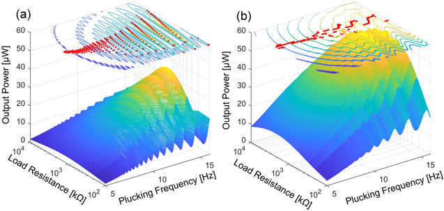
Figure 7. Output power comparison between (a) the non-bistable harvester with the standard circuit (NB-STD) and the (b) bistable harvester with SSHI (B-SSHI) for different operating frequencies and load resistances. The input force is the same in both cases. Contour plots illustrates the variation of output power. The red dots on the contour plots are the optimal output power for different driving frequencies.
Download figure:
Standard image High-resolution imageThe significant variation of the optimal load resistance in the NB-STD configuration are mainly caused by the following factors, including the variation of beam resonant frequency, power fluctuation at high frequencies (e.g. >6 Hz) and the electrical damping variation caused by connecting different loads. Figure 8 illustrates the voltage variation on the storage capacitor Cs for different load resistances. Due to the shift of the ripple frequency for different loads, the optimal load for a specific plucking frequency varies significantly, as shown in figure 8(a) and the red dots in figure 7(a). By comparing the shift in figures 8(a) and (b), we can state that although the resonant frequency shift also appears in the B-SSHI case, the voltage fluctuation is significantly attenuated over a wide frequency range. This attenuation allows the output power to exhibit a stable performance for different resistances at specific frequencies. Figure 9 compares the output impedance differences between the NB-STD and B-SSHI configuration over a wide frequency range. For the NB-STD configuration, the output power varies significantly for different frequencies. When this variation is combined with the shift of resonant frequency, the optimal load resistance is unstable and varies in a wide range, as also shown by the red dots on the contour plot in figure 7(a). For example, as shown in figure 9(a), at 15.1 Hz, the optimal resistance in the selected resistance set is 1 MΩ, and the output power is 37.4 μW, whereas at at 14.5 Hz, the optimal output power is 12.5 μW at 2.8 MΩ. This serious variation not only affect the output power but also increases the difficulty in selecting an appropriate fixed load resistance to obtain the optimal output.

Figure 8. Steady-state voltage on the storage capacitor Cs versus beam plucking frequency for different load resistances. (a) NB-STD configuration and (b) B-SSHI configuration.
Download figure:
Standard image High-resolution image
Figure 9. Comparisons of output power versus beam plucking frequency for different resistive loads. (a) Non-bistable harvester with the standard circuit (NB-STD) and (b) bi-stable harvester with the SSHI circuit (B-SSHI).
Download figure:
Standard image High-resolution imageIn comparison, the B-SSHI configuration addresses these concerns and improves the output power further by adopting bi-stability and SSHI. As shown in figure 9(b), the power fluctuation is greatly weakened. The optimal load resistance still varies for different operation frequency, but the deviation of the output power for different loads are marginal. Therefore, the B-SSHI configuration improves both the output power and the output resistance adaptability of a typical FRUCH. This is extremely beneficial to practical applications to obtain a nearly optimal output power for different frequencies using a fixed load resistance.
4. Experimental study
4.1. Experimental set-up
An experimental study was conducted to validate the theoretical model and the numerical analysis. The B-SSHI configuration was implemented, as shown in figure 10. The rotational motion is provided by a stepper motor whose speed can be precisely adjusted by a control circuit as depicted in figure 10(a). The piezoelectric beam and the fixed magnets are mounted on two linear positioning stages respectively, by which the gaps among magnets can be accurately controlled. A laser displacement sensor was adopted to record the beam dynamics.

Figure 10. Experimental set-up. (a) Bistable frequency up-converting harvester and (b) SSHI circuit implemented on a printed circuit board (65 × 45 mm). The beam dimensions are 33.5 mm × 1.5 mm × 0.2 mm.
Download figure:
Standard image High-resolution imageThe SSHI interface circuit was built on a printed circuit board, as shown in figure 10(b). A typical self-powered P-SSHI circuit is adopted in this study based on [44, 46]. The design and the component parameters are summarized in appendix B. The overall dimensions of the board are 65 × 45 mm. Different resistive loads were connected in parallel to the storage capacitor (10 μF) during the test. It is worth mentioning that the stepper motor, three-axis linear positioning stages and the laser displacement sensor were adopted in this experimental set-up for the purpose of accurate control of the experimental study. For practical applications, the place of the rotating stage is taken by the rotating host structure, e.g. a turbine rotor, and the positioning stages and laser sensor are unnecessary.
4.2. Results and discussion
Figure 11 provides a comparison between theoretical and experimental results. A close match was obtained in terms of beam operation frequency, vibration amplitude and damping ratio. This comparison verifies the validity of the theoretical model for both the NB-STD and the B-SSHI configurations. Through the comparison between two configurations, the benefits of the B-SSHI case in improving the output powered and attenuating the power fluctuation can be illustrated by the displacement and output voltage curves. Compared with the displacement for the NB-STD configuration (figures 11(a) and (e)), the displacement for the B-SSHI configuration (figures 11(c) and (g)) is improved, when operating in the double-well mode, as shown in ① in figure 11(g); after a few cycles, the beam (for B-SSHI) settles in to the single-well mode with limited vibration amplitudes, as shown in ② in figure 11(g). The improved amplitude in ① is beneficial to enhancing the output power, and the reduced amplitude in ② can reduce the interference between vibrating beam and the coming plucking force and the power fluctuation issues caused by this interference.

Figure 11. Comparison of theoretical (a)–(d) and experimental (e)–(h) results, including beam displacement (a), (c), (e) and (g) and beam output voltage (b), (d), (f) and (h). (a), (b), (e) and (f) are results for the NB-STD configuration; (c), (d), (g) and (h) are results for the B-SSHI configuration. The input plucking frequency was 12.5 Hz for all cases.
Download figure:
Standard image High-resolution imageThe improved voltage is the contribution from the adaptation of both bi-stability and the SSHI circuit, as discussed earlier in figure 6. The SSHI circuit increases the output by reversing the output voltage at its extrema, allowing more charges to be accumulated. This improvement is indicated by comparing the output voltage between the NB-STD case in figures 11(b) and (f) and the B-SSHI case in figures 11(d) and (h). This increased electrical output also means that higher electrical damping is applied on the vibrating beam. The increased dampening attenuates the vibration more quickly, minimizing the interference between the vibrating beam and the forthcoming driving magnet and reducing the power fluctuation issue at high frequencies.
The output impedance for both configurations was measured at the storage capacitor Cs by connecting different resistive loads, as shown in figure 12. A significant improvement in output power was obtained in the B-SSHI configuration, 19.2 μW at 2 MΩ compared to the NB-STD configuration, 5.9 μW at 900 kΩ. The experimental results are compared to the numerical results. A close match was achieved.
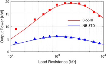
Figure 12. Impedance matching curves at the storage capacitor Cs for both NB-STD and B-SSHI configurations at 6.25 Hz. Lines are numerical results, and marks are for experimental data. A 10 μF capacitor was used for storage.
Download figure:
Standard image High-resolution imageThe optimal resistance varies for different beam plucking frequencies, as illustrated earlier in figure 7, especially for the NB-STD case. Therefore, the optimal output power cannot guaranteed by a fixed load resistance over a wide frequency range. However, considering the moderate variation of the optimal load resistance for the B-SSHI configuration, a fixed resistance (e.g. 2 MΩ) can be used for system implementation simplicity while maintaining the output performance. This is another advantage provided by the B-SSHI configuration.
The dynamics of four configurations under different operation frequencies were studied experimentally and compared with the numerical results, as shown in figure 13. A close match was also obtained in the frequency domain, showing the validity of the theoretical model. The benefits of the B-SSHI configuration in both reducing power fluctuation and increasing the output power are illustrated by comparing different configurations. The advantages are clearly illustrated over a wide frequency range (1–16 Hz). The enhancement can be up to 525% compared to a harvester without bi-stability or a SSHI circuit. Meanwhile, the power fluctuation is greatly attenuated, compared to other configurations.

Figure 13. Performance comparison for different configurations: (a) Numerical results and (b) experimental results. The output power was measured with a constant resistive load (2 MΩ). Four configurations are compared, including harvesters with or without bi-stability in associate with a standard (ʽstd') or an SSHI interface circuit. The input force is the same for all cases.
Download figure:
Standard image High-resolution imageThese comparisons, eventually, validate the capability of the theoretical model and the numerical solution to study the coupled nonlinear dynamics including both bi-stability and SSHI in a holistic manner. A close match is obtained between the numerical and experimental results. This theoretical model can be helpful in terms of designing harvesters with coupled nonlinearity and electromechanical dynamics.
5. Conclusions
In this work, an efficient way to utilize piezoelectric conversion is presented by integrating bi-stability and a SSHI circuit into a FRUCH. Advantages of these technologies are combined to enhance the system performance: (1) frequency up-conversion converts any low-frequency and random motion into a uniform single-frequency output waveform. This is ideal for the SSHI circuit to generate appropriate switching events; (2) bi-stability allows the system to operate in a high-energy orbit to generate higher output power; the transition from the double-well mode to the single-well mode in one plucking cycle limits the beam displacement at the end of one plucking cycle, which is ideal to reduce the power fluctuation issue at high frequencies; (3) the SSHI circuit further improves the output power due to its improved power conversion capability. This enhanced output power means that stronger electrical damping is applied on the transducer. This added damping allows the beam to dampen the vibration more quickly and consequently alleviates the power fluctuation at high frequencies.
The nonlinear behaviors are theoretically modeled and numerically studied in a coupled way, which, to the authors' knowledge, has never been achieved before. Coupled system dynamics, which could not be obtained from circuit simulation methods, are investigated for different load resistances and input beam plucking frequencies. The validity of the model was then examined by an experimental study, and a close match was obtained. Significant power enhancement (up to 525%), reduced power fluctuation and more stable output power and impedance performance have been achieved over a wide bandwidth at low frequencies (1–16 Hz). The energy conversion efficiency was improved from 49.8% in the NB-STD configuration to 62.2% in the B-SSHI configuration in a numerical study. This work provides an effective design to harness kinetic energy over a wide frequency range at low frequencies and a novel solution for solving coupled nonlinear behaviors including both bi-stability and a SSHI circuit.
Appendix A.: Beam applied force and bending illustration
The beam deflection and force relationships among magnets are illustrated in figure A1. The beam is bending in the y-axis direction under the plucking motion from the driving magnetic force, as shown in figure A1(b). The fixed magnet provides the force components for creating two stable positions for the cantilever, as shown in figure A1(a). This diagram is used when calculating the magnetic forces among magnets using equation (3).
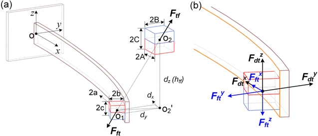
Figure A1. Piezoelectric cantilever deflection and force relationship illustration. (a) Beam deflection direction and the force relationship between the tip and fixed magnets; (b) Forces between the tip and driving magnets [35].
Download figure:
Standard image High-resolution imageAppendix B.: Typical self-power SSHI circuit design
Figure B1 illustrates the self-powered circuit used in this work with the specific values selected. The SSHI interface circuit was built on a printed circuit board, as shown in figure 10(b). The diodes are 1N4148W, and the transistors are MMBT3904 (NPN) and MMBT3906 (PNP). Different resistive loads R2 were connected in parallel to the storage capacitor C3 during the test.

Figure B1. The self-powered P-SSHI circuit design used in the PCB in figure 10(b). The component values are shown in the figure.
Download figure:
Standard image High-resolution image