


Abstract
Clamping loss limits the quality factor of mechanical mode in the optomechanical resonators supported with the supporting stem. Using the mechanical bound state in the continuum (BIC), we have found that the mechanical clamping loss can be avoided. The mechanical quality factor of a microsphere could be achieved up to 108 for a specific radius of the stem, which forms a mechanical BIC with the combination of the symmetry protected mechanism and the single resonance mechanism. Such a mechanism is proved to be universal for different geometries and materials, thus can also be generalized to design high quality mechanical resonators.
Export citation and abstract BibTeX RIS

Original content from this work may be used under the terms of the Creative Commons Attribution 3.0 licence. Any further distribution of this work must maintain attribution to the author(s) and the title of the work, journal citation and DOI.
1. Introduction
The optomechanical interactions, which have been motivated more than thirty years [1–4], take place via either the radiation pressure and gradient forces induced by the optical fields [5–7] or nonlinear processes such as Brillouin scattering [8, 9]. These interactions can play a special role in the quantum state transfer between the optical and mechanical motions [10–12]. The ubiquitous nature of mechanical degrees of freedom can enable a macroscopic mechanical oscillator to couple to nearly all types of quantum systems, including charge, spin, atomic, and superconducting qubits, as well as photons at nearly any wavelength [13, 14]. The radiation-pressure-induced coherent mechanical oscillations in whispering gallery mode (WGM) microresonators have been observed in experiment about a decade ago [6]. Such optomechanical resonators have been used to obtain a variety of coherent optical processes, such as optomechanical induced transparency (OMIT) [15–17], optomechanical light storage [18], and coherent optical wavelength conversion [17, 19]. Radiation pressure cooling of mechanical oscillators to their ground states has also been realized experimentally in these optical resonators [20, 21]. In all these applications, the intrinsic mechanical quality (Q) factor is important, which limits the phonon lifetime and the fidelity of interconversion between phonon and other excitations.
The dominate origins of mechanical energy dissipation can be divided into three categories: fluid-structure interactions, material damping and clamping damping [22, 23]. Different strategies exist to reduce the relevant damping channels. To eliminate the fluid-structure interactions or air damping, the most effective strategy is to place the device in the low pressure vacuum chamber [24]. For the material damping, controlling the type, distribution, density of defects, the operating temperature, and designing material are usually considered [23]. Although the material damping faces the fundamental technique challenges, the clamping damping can be eliminated by clever designs, such as supporting the resonator at its nodal points [25, 26] or surrounding the resonator with phononic band-gap structures [27].
Here, we propose the mechanical bound state in the continuum (BIC) to reduce the clamping damping and to improve the mechanical Q in the silica microsphere. The BIC, which was first proposed by Von Neuman and Wigner in 1929 [28], represents a class of bound states with energy inside the continuum spectrum but without the coupling to the continuum [29]. The BIC has been found in various systems , such as electronic, electromagnetic and acoustic structures [30–34]. The BICs are mainly attributed to four types of mechanisms [29, 35, 36]. (i) The Fabry–Perot BIC. If radiation loss is the only loss channel for a resonator, we can use two such resonators as a Fabry–Perot cavity to trap the radiation wave, and the BIC is formed when the phase accumulation between the two resonators is an integer number of half wavelengths. This mechanism has been applied to study complete channel drop tunneling from one continuum to the other [41, 42], to dynamically confine electrons by a quasi-one-dimensional double-well system [43]. Particularly, optical BIC of the Fabry–Perot mechanism has been reported in [30]. (ii) The Friedrich–Wintgen (FW) BIC, which is formed by destructive interference of resonances from different channels (one of the resonance widths vanishes). In experiments, the FW BIC has been observed in metamaterials [44] and in acoustic duct resonators [45, 46]. (iii) The symmetry protected BIC. If the symmetry of the resonance mode and the modes in the continuum belongs to a different class, the coupling between them will be forbidden. Then the resonance is protected from the leakage to the continuum by the symmetry [32, 37–40]. (iv) The last one is a single resonance BIC, which is realized by tuning radiation loss of the single resonance to zero. For example, it has been demonstrated to tune the resonance widths with magnetic field [47], or tune the finger gate potential through Π- and Z-shaped waveguides [48], or tune the quantum dot width in open rectangular quantum dots [49].
In this paper, we found the elastic wave dissipation of stem supported microsphere and microdisk structures can be eliminated through symmetry-protection and geometry engineering as well. By extending the BIC phenomena to the mechanical system, we demonstrate that the leakage of spherical vibration to the supporting stem can be canceled. The mechanical Q factor limited by the clamping loss can be as high as 108 (limited by the precision of simulation) for BIC with the appropriate supporting stem. We believe that the BIC is a novel and efficient method for decreasing the mechanical clamping loss, and it can be used for the designing of other phononic structures to overcome the phonon dissipation.
2. Model
In this work, we illustrate the basic principle of the mechanical BIC by the simple microsphere on stem structure (figure 1(a)). In the experiment, the silica microsphere is normally fabricated by a CO2 laser beam and supported at the end of the fiber tip [50]. In past decades, the silica microsphere on fiber stem has been extensively studied in experiment due to its ultrahigh optical Q factor (up to 1010 [51, 52]) and easy fabrication. Thus, we build the model in the COMSOL multiphysics, as shown in figure 1(a). The microsphere with radius of R is supported by a stem with radius of r. The stem length is L with a perfectly matched layer of I. The parameters of the model are  =
=  . Similarly to the optical modes [50], the acoustic waves in silica microspheres can be identified by radial (q), orbital (l), and azimuth (m) numbers. In the stem, there are three types of elastic waves for different polarizations, including pressure wave (displacement along propagation direction), flexural wave (out-of-plane transverse displacement) and shear wave (in-plane transverse displacement) [53]. In spheres, the modes are divided into two categories: spheroidal and torsional modes, which are hybridized flexural and pressure waves and pure shear waves, respectively. For optomechanical applications, we are mostly interested in those spheroidal modes since the volume change of the torsional mode is zero. In addition, it has also recently demonstrated that the spheroidal mode can couple with magnons efficiently [54].
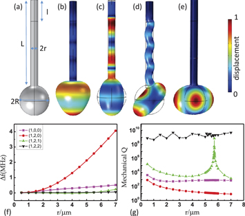
Figure 1. Mechanical modes in the microsphere. (a) The microsphere with the supporting stem. (b) The radial breathing mode  with frequency of 127.10 MHz and mechanical Q = 721. (c)
  mode with frequency of 89.20 MHz and Q = 15. (d)
  mode with frequency of 87.48 MHz and Q = 3874. (e)
  mode with frequency of 87.53 MHz and
  . The parameters
  of the silica microsphere are
  . The color represents the displacement of mechanical vibration. (f) The frequency drift versus the radius of the stem, for fixed sphere size. (g) The mechanical Q versus the radius of the stem, for fixed sphere size.
Download figure:
Standard image High-resolution imageShown in figures 1(b)–(e) are the typical spheroidal modes ( ), (
), ( ), (
), ( ), (
), ( ), respectively. From the simulated distributions of deformation, we find that there are three different clamping conditions: the spherical vibration coupling with the pressure wave in the supporting stem for (
 ) and (
 ) modes (figures 1(b) and (c)), the excited flexural wave in the stem for (
 ) (figure 1(d)), and almost no elastic wave dissipation in the stem for (
 ) mode. The intuitive explanation of the excited pressure wave for the
  is that the motion of the sphere is at the polar point (antinode), or pure radial motion at the clamping point, which can only compress and stretch the stem in z-direction (cylindrical coordinate for stem). In contrast, for (
 ) mode with
  , there is only vibration along the equator of the sphere (we may call this type of mode as mechanical WGMs), so there is no displacement at the polar point, i.e. the loss is zero. When increasing the stem size r, we can see that the frequencies of (
 ) and (
 ) modes change a lot while the mechanical Q factors decrease monotonously. It indicates that the coupling between stem and these modes is proportional to the area of the stem end (
 ). For the mechanical WGMs ((1, 2, 2) mode), both the frequency and mechanical Q remain constant for different r, respectively, and the mechanical Q is larger than 108 with small fluctuations due to the numerical errors.
The ( ) mode shows very different and interesting behavior from the other two types of modes. From the field distributions, we can see that at the contact point of the sphere and the stem, there is zero mean displacement in z-direction but non-zero displacement in transverse direction. The flexural motion (out-of-plane transverse displacement) of stem shows similar displacement in z-direction and transverse direction. Shown in figure 1(g), there is a singular peak for (
 ) mode at
  . At the peak, the mechanical
  is again limited by the precision of numerical simulation.
3. Mechanical BIC
For strong optomechanical interaction in the sphere, we prefer the (1 ,2, 1) mode in figure 1(d) and (1, 2, 2) mode in figure 1(e). The ( ) mode shows zero net displacement in the equator and non-zero orbit angular momentum, thus can only couple with light through the Brillouin scattering process [8, 9], which requires two optical modes to satisfy the phase matching and energy conservation relations. Also, the mechanical loss of the breath type of mode is very large due to the strong radiation pressure coupling and the pressure wave leakage to the stem. Besides, in practical experiments, the supporting stem that is smaller than 1 μm to achieve high mechanical Q factor would be fragile.
Therefore, the ( ) mode is an optimal choice, in which mechanical Q factor can be modulated via stem size. The singular high-Q peak in the (
 ) mode is useful and the details about the mechanism of the phenomenon are in the following.
In figure 2(a), the mechanical Q of ( ) mode is shown as a function of the ratio of stem radius to sphere radius t = r/R. At the singular point, the mechanical Q exponentially decays with the deflection of the optimal ratio. This extremum of the mechanical Q means that the propagating flexural wave in the stem cannot be excited by the sphere vibration, which forms a mechanical BIC. Similar phenomena may also be observed for other mechanical modes, such as all the higher order
  modes. To verify such mechanical BIC mechanism in the spherical mechanical microresonator, the higher order
  modes with
  are studied and the results are plotted in figures 2(a) and (c)–(e). All these modes show similar singular high mechanical Q factors with specific t. At those optimal t, the displacement of stem exponentially decreases with the distance to the sphere, which indicates that the propagating elastic wave in the stem is not excited. We should note that the BIC for mode (
 ) is not supported in the silica sphere, since the spheroidal mode couples to the high loss torsional mode by the perturbation of stem. Therefore, we modified the Young'(s) modulus to
  GPa and the Poisson ratio to 0.12, and plotted the results in figures 2(a) and (c).
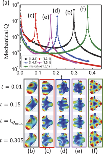
Figure 2. Universality of the mechanical Q extremum of five mechanical systems versus the ratio t of r/R. (a) The black, red, blue, magenta lines show the ( ), (
), ( ), (
), ( ), (
), ( ) modes with fixed sphere radius
  . The green line shows the (
 ) mode with the quasi-2D microdisk (
 ) supported by the beam. (b)–(f) The legends in black, red, blue, magenta, green-colored boxes are the displacements of the mechanical systems with
  . The corresponding (
 , Qmax) are (
 ), (
), ( ), (
), ( ), (
), ( ), (
), ( ), respectively.
Download figure:
Standard image High-resolution imageThen, we testify the existence of the BIC for different material properties. As shown in figure 3, the mechanical Qmax and the eigen frequency for  mode are plotted versus Young's modulus and Poisson ratio of the material. Firstly, for R = 12
  , the eigen frequency increases as the Young's modulus rising from 30 to 100 GPa. The mechanical Qmax for BIC retains up to 108. Due to the precision limited by numerical simulation, the fluctuation of the mechanical Qmax above 108 is inconspicuous. On the contrary, the optimal ratio t is stable as the Young's modulus of the structure adds up. As shown in figures 3(c) and (d), when varying the Poisson ratio from 0.11 to 0.25, the eigen frequency decreases, and t rises up while the mechanical Qmax remains high.

Figure 3. The influence of the eigen frequency, the optimal t and the mechanical Qmax by material. (a)–(b) The mechanical Qmax, and the optimal rate t versus the Young's modulus of the microsphere with the stem, rising from 30 GPa to 100 GPa. The inset in (a) shows the eigen frequency versus the Young's modulus from 30 GPa to 100 GPa. (c)–(d) The mechanical Qmax , and the optimal t versus the poisson ratio of the structure varying from 0.11 to 0.25. The inset in (c) shows the eigen frequency versus the poisson ratio from 0.11 to 0.25.
Download figure:
Standard image High-resolution imageFurther generalization of the mechanical BIC can apply to the quasi-2D structure, such as the suspended microdisk attaching to an auxiliary beam [55]. As shown in figure 2(f) , the 3rd order mode, which corresponds to the  mode in microsphere, shows in-plane standing wave profile along the boundary of the disk. The mode is combined radial and tangential displacements, and the corresponding leaking wave in beam is the in-plane flexural wave. Very similar to the microsphere case, we observe the leakage forbidden by changing the beam width, which leads to the BIC phenomenon in structures on photonic chips.
4. Mechanism
To analyse the underlying mechanisms of the observed mechanical BIC, we take the 3rd order modes in microdisks as an example. As shown in the figures 4(a) and (c), we obtain two 3rd order modes with near-degenerate frequencies (about 107.8 MHz for mode A and 109.2 MHz for mode B). Actually, the two modes can be interpreted as the even and odd superposition of waves propagating in opposite directions, which leads to cos- and sin-like standing wave profile. When the stem size is very small, the two modes should be degenerate due to the reciprocal properties of elastic wave in the dielectric material. According to the four mechanisms introduced in the Introduction section, we found that
- i.The mechanism of Fabry–Perot BICs is not applicable for our system, since there is only one resonator.
- ii.Although there are two near-degenerate modes (A and B in figure 4), the Friedrich–Wintgen (FW) mechanism cannot explain the observed BIC either. For the FW mechanism, the frequencies of two modes are brought together when achieving the BIC. However, in our case, the mode degeneracy are lifted by the stem when BIC is formed. In addition, from the displacement profiles for modes A and B (as shown in figures 4(a) and (c)), the two modes actually are coupling to different radiative waves in stem. The mode A couples with the flexural wave of stem, while the mode B couples with the pressure wave of the stem. Thus, the interferences between modes A and B cannot lead to the cancellation of the coupling to the continuum, which is contradict to the FW mechanism.
- iii.The symmetry does play a role in the mechanical BIC. As explained above, the stem lifts the degeneracy of the elastic waves and different symmetry with the two modes in the disk. As shown in the figures 4(b) and (d), the displacement of mode A in y-direction (uy) is very small at the location of the stem, while the mode B has maximum of uy at the location of the stem. Actually, the profile of uy for modes A and B can be classified to be odd and even mirror symmetry with respect to the stem. In contrast, the distribution of uy for the pressure wave of the stem is even symmetric (figure 4(d)). Additionally, the displacements in the x-direction (ux) for mode A and the pressure wave have even and odd symmetry, respectively. Therefore, the mode overlap between mode A and the pressure wave in continuum is zero, in other words mode A is protected from coupling to the pressure wave in stem.
- iv.The single resonance BIC mechanism for mode A. According to figure 4(b), mode A can still couple to the flexural wave in the stem, since the uy for both of them are odd-symmetric and ux for both of them are even-symmetric. The overlap of ux for two modes is approximately proportional to the size of the stem, i.e.
 with coefficient . For the overlap of uy, it can be approximated by with coefficient . Because the overlaps of ux and uy are of different sign, the coupling between the mode A and flexural wave in stem happens to vanish ( ) for some specific geometry parameters and results in the BIC phenomenon.


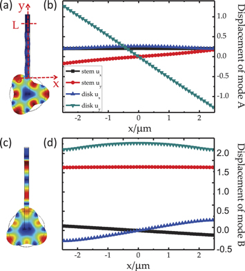
Figure 4. Displacement distributions of 3rd order modes of a microdisk supported by a stem. The radii of the microdisk and the stem are 20 μm and 2.5 μm, respectively. (a) and (c) Are the total displacement distributions of odd (mode A) and even (mode B) symmetric modes, respectively. The frequencies of modes A and B are 107.8 MHz and 109.2 MHz, and the Q factors are  and 25, respectively. (b) and (d) The displacements of the stem and microdisk at the cross-section of the stem, with
  for displacement in the x(y)-direction.
Download figure:
Standard image High-resolution imageTherefore, we conclude the mechanism of the mechanical BIC in the stem supported microsphere and microdisk is the combination of the symmetry protected mechanism and the single resonance mechanism.
5. Discussions
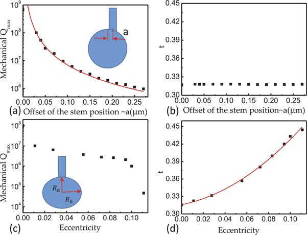
All of these results confirm the universality of the mechanism of mechanical BIC, which is applicable to other materials and structures. For practical applications of the mechanical BIC, we should also consider the imperfections of the fabricated microstructures. For example, during the fabrication of the silica microsphere, due to the surrounding environment perturbations (such as wind and vibrations) and gravitation force, the sphere may not be perfectly spherical and the stem may not point to the center of sphere.
Figure 5(a) shows that the achievable mechanical Qmax for BIC decreases with the increased offset of the stem. When the offset is  for
for  , the mechanical Qmax value limited by the clamping loss drops down to
  . It indicates that the symmetry is important for the high mechanical Qmax. In figure 5(b), the optimal t is almost constant for different offsets. For the gravity induced small eccentricity of the microsphere, the achievable mechanical Qmax also reduces, as shown in figure 5(c). Define the eccentricity as
  , where Rb and Ra are the radii of long and short axes. There is a critical eccentricity around 0.1, beyond which the mechanical Qmax reduces dramatically to be smaller than 105. The results in figure 5(d) indicate that the optimal t rises quickly as the eccentricity grows up. In practical experiments, the gravity induced eccentricity is usually around
  , which still permits Qmax to be larger than one million.
Figure 5. (a)–(b) The mechanical Qmax and the optimal rate t versus the offset of the supporting stem, respectively. (c)–(d) The mechanical Qmax and optimal rate t versus the eccentricity of the microresonator, respectively. The fitted curves of (a) and (d) are polynomial fititngs.
Download figure:
Standard image High-resolution image
In previous experiments, the measured mechanical Q of silica microspheres is limited to be 2 × 10⁴ in vacuum and cryogenic temperatures [20, 21]. It is believed that it is the material limitation, due to the absorption of two-level system (TLS) in non-crystal silica. However, such limitation can be resolved by pump the system to saturate the TLS absorpation at low temperature [56]. By this technique, the million level Q of mechanical BIC is possible for silica whispering gallery microresonators and will benefit the single photon level optomechanics experiments. For example, the lifetime for mechanical mode with  and
and  Hz is
Hz is  , which is one excellent candidate for quantum memory.
6. Conclusion
The mechanical bound states in the continuum are studied, whose elastic energy loss through clamping structures is forbidden. The intrinsic mechanism is the combination of the symmetry protected mechanism and the single resonance mechanism. The detailed studies on different mechanical modes, different mechanical resonator structures and materials confirm the universality of the mechanical bound states in the continuum. Therefore, the mechanism studied in this paper can be used for the design of other mechanical resonators, in the field of optomechanics and electromechanics.
Acknowledgments
CLZ thanks H Wang for stimulating discussions. The work was supported by the Strategic Priority Research Program (B) of the Chinese Academy of Sciences (Grant No. XDB01030200), National Basic Research Program of China (Grant Nos. 2011CB921200 and 2011CBA00200) and the National Natural Science Foundation of China (Grant Nos. 61308079, 61575184 and 61505195), Anhui Provincial Natural Science Foundation (Grant No. 1508085QA08), the Fundamental Research Funds for the Central Universities.