


Abstract
The secure transfer of information is critical to the ever-increasing demands of the digital world. Continuous-variable quantum key distribution (CV-QKD) is a promising technology that can provide high secret key rates over metropolitan areas, using conventional telecom components. In this study, we demonstrate the utilization of CV-QKD over a 15 km multi-core fiber (MCF), in which we take advantage of one core to remotely frequency lock Bob's local oscillator with Alice's transmitter. We also demonstrate the capacity of the MCF to boost the secret key rate by parallelizing CV-QKD across multiple cores. Our results indicate that MCFs are promising for the metropolitan deployment of QKD systems.
Export citation and abstract BibTeX RIS

Original content from this work may be used under the terms of the Creative Commons Attribution 4.0 licence. Any further distribution of this work must maintain attribution to the author(s) and the title of the work, journal citation and DOI.
1. Introduction
Quantum key distribution (QKD) is an innovative technology used to securely distribute cryptographic keys among spatially separated users [1, 2]. It is based on encoding randomly chosen bits on individual quantum states and then performing independent measurements on those bits. Using classical post-processing techniques and a classical communication channel, a secure and shared secret key can be deciphered by remote parties (typically referred to as Alice and Bob). Many experiments have shown that QKD is now a mature technology [3–7]. QKD protocols can be divided into two broad categories: discrete variable (DV) and continuous variable (CV) QKD [1, 2]. In the former, a discrete set of quantum states is employed in conjunction with single-photon detectors [1, 2], whereas in the latter, a broader set of states is employed in conjunction with coherent detection [8]. CV-QKD has recently garnered significant attention because it can be implemented with conventional telecom components that can operate at room temperature, enabling cost-effective implementation that is compatible with current network infrastructures. In particular, CV-QKD can offer higher secret key rates in metropolitan networks [1, 2]. Moreover, compared to DV-QKD, CV-QKD can be mass-produced by using photonic integrated circuits (PICs) since coherent receivers can be integrated in an easier way [9].
In terms of security, CV-QKD has been proven to be reliable against general collective attacks [10–12]. To avoid security loopholes due to the local oscillator (LO) and detector, the use of true LO [13, 14] and measurement-device-independent (MDI) [15, 16] schemes can be considered. In experiments, long transmission distance of up to 202.81 km [17], high speed of up to 63.7 Mb s−1 [18] and high security MDI quantum cryptography [15, 19, 20] for CV-QKD have recently been achieved. Finally, the coexistence of CV-QKD and classical signals in a field-installed fiber have also been investigated in [21, 22].
Multi-core fibers (MCFs) will play a fundamental role in future classical communications for several reasons. First, MCFs can solve the upcoming shortages in network capacity [23]. In theory, the achievable rate of an N-core MCF corresponds to N times that of a single-mode fiber (SMF) [24]. Second, MCFs have lower footprints than a bundle of standard SMFs, which is highly significant in the deployment process (e.g., in telecom data centers where space is limited). They also enable a single amplifier to be used for all the cores, which decreases the resources required and increases the energy efficiency [25]. Third, MCFs are perfectly compatible with PICs for multiple-input-multiple-output applications, and hence they are expected to be widely utilized in both core and metropolitan networks [26, 27]. Finally, MCFs have demonstrated low levels of crosstalk between the different cores as well as losses similar to standard SMFs, which indicates that they are suitable candidates for co-propagating quantum and classical signals in different cores or within the same core [28–31].
MCFs are also beneficial for quantum communication. For example, greater phase stability occurs among the different cores because the co-propagated signals in different cores experience similar environmental effects that enable the transmission of spatially encoded photonic quantum states [32]. Furthermore, MCFs are well suited to the transmission of high-dimensional photonic states that use the transverse degree-of-freedom of a single photon [33]. For example, MCFs initially performed QKD using path-encoded qudits over a distance of 300 m [6], as well as using silicon-based PICs [34]. In [35], a 411 m 19-core MCF was used to distribute polarization-entangled photon pairs through 12 channels simultaneously. In other experiments, the distance for quantum communication protocols was extended to 2 km and 11 km [32, 36]. MCFs have also been used to construct multiport beam splitters for applications in quantum information [37].
The use of CV-QKD in MCFs has not been extensively studied. In 2018, it was demonstrated that the fan-in and fan-out devices required in MCFs degrade the performance of CV-QKD protocols [38], but the total secret key rate can be increased through parallelization. In that same year, a proof-of-concept of a quantum-to-the-home network that employed CV-QKD through a 9.8 km 7-core MCF was demonstrated [39]. In [39], an aggregated secret key rate of 33.6 Mb s−1 was obtained by using a discrete modulation with four symbols. However, no information was provided on how the secret key was calculated, and the specific details of the implementation were not described. In 2019, a 10.1 km 19-core MCF was used to demonstrate classical and QKD transmission [31]. In this case, six cores were used for the QKD and 13 cores were used for the classical coherent signals.
In this study, we implement a Gaussian-modulated coherent state (GMCS) CV-QKD protocol [40] with a true LO [41–44] across a 15 km MCF, the longest distance over which CV-QKD has been transmitted with these fibers. We show that the GMCS CV-QKD protocol can be deployed in MCFs to boost the secret key rate by parallelizing CV-QKD across multiple cores. In particular, a potential aggregated secret key rate value of 2.3 Mb s−1 is achieved. In addition, we show that one of the cores can be used to transmit an auxiliary signal, which is typically required in QKD implementations. In our case, this signal allows Alice and Bob's lasers to be frequency locked. This scheme enhances the spatial sharing capabilities of MCFs (which are more advantageous than a single fiber dedicated for this purpose) and is an interesting alternative to wavelength-sharing over an SMF. Finally, our results provide the potential for advancing the deployment of CV-QKD systems in metropolitan networks.
2. Description of experimental setup
The experimental setup is illustrated in figure 1. In inset, we schematically depict the transmitted signal from Alice to Bob, in which the reference pulses are interleaved between the pulses containing the quantum states. The reference pulses were used to recover the phases of the quantum states by enabling not only the estimation of the phase difference between the laser source and LO, but also the phase variations caused by the channel [44, 45]. The pulses had a width of 4 ns with a pulse rate (R) of 31.25 Mpulses s−1.

Figure 1. Experimental setup. (Inset) Transmitted signal from Alice to Bob, in which reference symbols are interleaved between the quantum symbols. (Acronyms) FPGA: field-programmable gate array; PM: phase modulator; AM: amplitude modulator; PD: photodiode; BS: fiber beam splitter; VOA: variable optical attenuator; ISO: optical isolator; PC: polarization controller; PoM: power meter; MCF: multi-core fiber; LO: local oscillator; AS: auxiliary signal used to lock the frequency of Alice's laser to the LO; QS: quantum signal; SW: optical switch; 90° OH: 90° optical hybrid; BPD: balanced photodetector; RTO: real-time oscilloscope.
Download figure:
Standard image High-resolution imageAlice's source was a 10 kHz linewidth continuous-wave (CW) external cavity laser (ECL) with a tunable single-mode operation in the entire C band. This laser was frequency-locked with Bob's LO at 1550 nm (see details below). The output of the ECL was fed into four electro-optic modulators that were connected in series. The first two modulators, one phase modulator (PM) and one amplitude modulator (AM1), were used to generate coherent states of light according to the GMCS protocol, in which both the X and P quadratures are independent and modulated following a zero-centered Gaussian random distribution [40]. The second amplitude modulator (AM2) was used to increase the extinction ratio of the light pulses, while the third amplitude modulator (AM3) was used to control the ratio of the intensity of the reference pulses to that of the quantum pulses (ρ) by adjusting the bias set point. A ρ value of 300 was determined to ensure a sufficient accuracy in the phase recovery process [46]. The electro-optic modulators were driven by a field-programmable gate array (FPGA) electronic board with a 1 GSa/s digital-to-analog converter unit. Two independent sequences of 211 pseudo-random values were used to generate the quantum states. The first one was related to the phase modulation, in which the values were uniformly distributed between 0 and 2Vπ−PM (the half-wave voltage of the PM). The second sequence was related to the amplitude modulation, in which the values followed a Rayleigh distribution between 0 and Vπ−AM1 (the half-wave voltage of the amplitude modulator AM1). The amplitudes and phases of the reference pulses remained constant. After modulator AM3, a 50:50 fiber beam splitter (BS1) and a PIN photodiode (PD1) were employed to automatically optimize the bias set point of the modulators using the FPGA. An electronic variable optical attenuator (VOA) was used to adjust Alice's modulation variance, which was defined as Vmod = 2⟨n⟩, where ⟨n⟩ is the mean photon number measured at Alice's output. To determine ⟨n⟩, a 99:1 fiber beam splitter (BS2), which sent 99% of the light to an optical power meter (PoM), was used. The light from the 1% output of BS2 was further divided by a 1 × 8 fiber beam splitter to simulate signals coming from six different QKD transmitters. The signals were connected to a fan-in device (Optoscribe), which was used to multiplex the signals into a 15 km 7-core MCF fiber spool (developed by Corning Incorporated). After transmission, the signals were demultiplexed using a fan-out device (Optoscribe). Including the fan-in and fan-out devices, the average insertion loss per core was 6.3 dB, the forward (backward) crosstalk was lower than 50 (74) dB, and the backscattering loss was lower than 33 dB (see figure 2).

Figure 2. 15 km 7-core MCF characterization: optical loss including fan-in and fan-out devices in the forward (left panel) and backward (right panel) directions.
Download figure:
Standard image High-resolution imageBob, which was connected to each core of the MCF being measured, consisted of the LO laser, another 10 kHz linewidth CW ECL biased to emit 48 mW of optical power. Its output was split in half using a 99:1 fiber beam splitter (BS3), with 1% of the transmitted power sent to Alice through core 1 (C#1) in order to lock the frequency of Alice's laser to the LO. C#1 was chosen because it exhibited the highest insertion loss (7.4 dB, see figure 2). On Alice's side, the frequency difference between both lasers was minimized by applying a voltage to a piezoelectric element present in the cavity of Alice's laser. This minimization process was performed in real time by the FPGA through the measurement of the signal resulting from the interference between Alice's laser and the LO. For this purpose, a PIN photodiode (PD2) and two 50:50 fiber beam splitters (BS4 and BS5) were used, as shown in figure 1.
The other output of BS3 on Bob's side was connected to a 90° optical hybrid (90° OH), which was then followed by two balanced photodetectors (BPDs). Both the X and P quadratures were simultaneously digitized using a 1 GSa/s real-time oscilloscope (RTO). To calibrate the shot noise variance, an optical switch (SW1) was used to block the incoming light from Alice. The electronic noise variance was measured by turning off a second switch (SW2) located at the LO input port of Bob's OH, as shown in figure 1 [45, 47]. Finally, the RTO bandwidth was fixed at 200 MHz, and an average clearance value of 16.7 dB was obtained over the bandwidth. The clearance was defined as the ratio of the shot noise power to the electronic noise power. A manual polarization controller was used at Alice and Bob's inputs to maximize the signal overlap. To prevent Trojan horse attacks, an optical isolator was placed at Alice and Bob's outputs [48].
The post-processing required to characterize the proposed system was performed offline. It included downsampling, quantum state phase recovery, pattern synchronization, and estimation of different parameters such as excess noise, channel transmittance, and secret key rate. The down-sampling process involved detecting the power peaks of the received signals. The phase shift of the ith quantum state ( ) was calculated via a linear interpolation between the phases of the ith and ith + 1 references (
 and
and  ), expressed as [44, 45]

where  and
and  and
and  are the received quadratures of the ith reference. Regarding pattern synchronization, the time offset was removed by performing a cross-correlation between the transmitted and received quantum states.
The excess noise at Bob (ɛ), measured in the shot-noise unit (SNU), was estimated using [45, 47]

where νelec is the electronic noise variance, 1 is the shot noise variance, and VB|A is the conditional variance given by [45, 47]

where η is the detection efficiency, qA = {XAi , PAi } and qB = {XBi , PBi } are Alice and Bob's quadrature data, respectively, and T is the channel transmittance. The channel loss was supposed to be controlled by an eavesdropper. Therefore, T was estimated via [45, 47]

where  is the inner product of Alice and Bob's data. Finally, the secret key rate (SKR), in bits per second, was estimated assuming the asymptotic limit and reverse reconciliation, and was expressed by [45, 47]

where β is the reconciliation efficiency [49], IAB is the mutual information between Alice and Bob, XBE is the Holevo bound, and Reff is the effective quantum pulse rate. In this case, IAB was determined using the previously defined experimental parameters via [45, 47]

3. Experimental results
Figures 3–5 show the experimental results for the proposed CV-QKD system using the 15 km 7-core MCF with C#2 (see figure 1). The transmission parameters are listed in table 1. Figure 3 shows the phase-space density of the received signal before and after the phase recovery process. In figure 3(b), the outer symbols correspond to the references, and the inner symbols are the quantum symbols that correspond to the received quantum states.

Figure 3. Phase-space density in arbitrary units (a) before and (b) after phase recovery using reference symbols when C#2 of the 15 km 7-core MCF was being tested.
Download figure:
Standard image High-resolution image
Figure 4. (a) Comparison of the first 40 symbols of Alice and Bob's data for the X quadrature when C#2 of the 15 km 7-core MCF was being tested. (b) Histogram of the X quadrature data for Alice and Bob.
Download figure:
Standard image High-resolution image
Figure 5. Results for 30 measurements taken over 90 min when C#2 of the 15 km 7-core MCF was being tested: (a) excess noise (ɛ), (b) channel transmittance (T), and secret key rate (SKR). Each measurement corresponded to a block size of 106 symbols or coherent states.
Download figure:
Standard image High-resolution image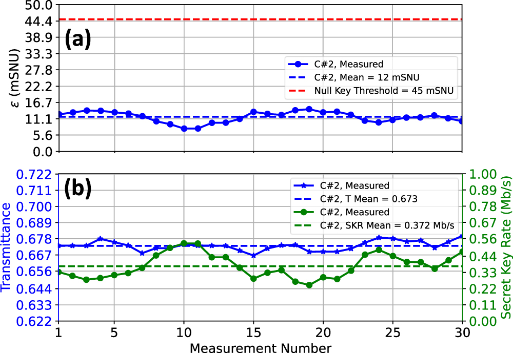
Table 1. Summary of the transmission parameters.
| Parameter | Value |
|---|---|
| Alice's modulation variance, Vmod | 1.764 SNU |
| Electronic noise variance, νelec | 21 mSNU |
| Reconciliation efficiency, β [49] | 0.95 |
| Detection efficiency, η | 0.18 |
| Ratio of intensity of reference pulses to that of quantum pulses, ρ | 300 |
| Effective quantum pulse rate, Reff | 15.625 Mpulses s−1 |
Figure 4(a) shows the 40 symbols of the X quadrature for Alice and Bob. Bob's data corresponded to the signals detected after the phase recovery process. A high level of correlation was observed. As shown in figure 4(b), Alice and Bob's quadratures followed zero-centered Gaussian distributions. The variance of Bob's quadrature distribution was  [45, 47].
Figure 5(a) shows 30 consecutive measurements of the excess noise ɛ taken over 90 min, and figure 5(b) shows the same for the channel transmittance T and the secret key rate SKR. In each measurement, a block size of 106 symbols (coherent states) was considered. The ɛ, T, and SKR values were calculated for each block of symbols independently. The shot noise and electronic noise variances were calibrated before each measurement. The excess noise ɛ, defined in equation (6), had a mean value of 12 mSNU and always remained below the threshold at which the secret key rate was null, as shown in figure 5(a). The measured ɛ threshold value, which depended on the experimental parameters, was 45 mSNU. The excess noise included the phase estimation error due to the time delay between the reference and quantum symbols and the noise due to the reference symbols. The transmittance T, which is given by equation (4), exhibited a mean value of 0.673. Figure 5(b) indicates that the value of T was stable over the measurement period, with a relative standard deviation of 0.5%. The SKR was determined by considering the values obtained for ɛ and T according to equation (5). A mean SKR of 0.372 Mb s−1 was achieved during the measurement period, with minimum and maximum values of 0.254 Mb s−1 and 0.533 Mb s−1, respectively, as shown in figure 5(b).
Finally, table 2 shows the CV-QKD system characterization using the 15 km 7-core MCF in terms of the ɛ, T, and SKR parameters for each core. The values obtained per core were the average of 30 measurements, with a block size of 106 symbols per measurement. Table 2 indicates that the results were similar across all cores, achieving a potential aggregated SKR value of 2.3 Mb s−1. This potential aggregated SKR was defined as the sum of all the obtained SKRs, as shown in table 2. Because the light coming from the QKD transmitter was divided into six cores (each of them measured individually at Bob), our experiment can be considered a simulation of a scenario in which six transmitters and six receivers were used. Note that the same Vmod was used in all the CV-QKD cores, being nearly optimal in all of them in order to maximize the SKR. In a practical scenario, they could be different within the margins of Vmod for positive SKR, which are relatively narrow for transmissions at medium and long-range distances. In terms of crosstalk between cores, the extension of the reported results to diverse values of Vmod is also pertinent. From preliminary measurements, we have observed that to obtain a noticeable degradation in the SKR of a particular core, the average power of the adjacent CV-QKD signals needs to exceed at least in two orders of magnitude the Vmod used in the reported experiment (see table 1), something that allows an adjacent power span that is higher than the practical Vmod value range.
Table 2. Summary of the characterization of the proposed CV-QKD system using the 15 km 7-core MCF in terms of excess noise (ɛ), channel transmittance (T), and secret key rate (SKR) for each core. Each value is an average of 30 measurements, with a block size of 106 symbols per measurement.
| C# | ɛ (mSNU) | T | SKR (Mb s−1) |
|---|---|---|---|
| 2 | 11.8 | 0.673 | 0.372 |
| 3 | 10.2 | 0.650 | 0.378 |
| 4 | 11.6 | 0.678 | 0.378 |
| 5 | 12.4 | 0.692 | 0.389 |
| 6 | 14.7 | 0.667 | 0.371 |
| 7 | 12.3 | 0.645 | 0.375 |
4. Conclusions
In conclusion, we have demonstrated the utilization of CV-QKD across a 15 km MCF, in which one of the cores was used to transmit an auxiliary signal to frequency lock two lasers. We have also demonstrated the capacity of the MCF to boost the secret key rate by parallelizing CV-QKD across multiple cores. In particular, a potential aggregated SKR value of 2.3 Mb s−1 was achieved. Finally, our results have the potential to advance the deployment of CV-QKD systems in metropolitan regions by taking advantage of next-generation telecom optical fibers.
Acknowledgments
This research was partially funded by the Horizon 2020 Framework Programme (820466), H2020 Marie Skłodowska-Curie Actions (713729), Ceniit Linköping University, the Swedish Research Council (2017-04470), QuantERA grant SECRET (2019-00392), MCIN with funding from European Union NextGenerationEU (PRTR-C17.I1), DGR-Next Generation Catalonia, CEX2019-000910-S [MCIN/AEI/10.13039/501100011033], Fundació Cellex, Fundació Mir-Puig, and Generalitat de Catalunya through CERCA.
Data availability statement
The data generated and/or analysed during the current study are not publicly available for legal/ethical reasons but are available from the corresponding author on reasonable request.
Disclosures
S Etcheverry and V Pruneri are shareholders of Luxquanta Technologies S. L., which is commercializing QKD systems.