
Abstract
One of the biggest challenges in implementing microalgae-based biofuels is the effective harvesting process. Filtration membrane has become one of the flexible methods in microalgae harvesting. This study investigated the harvesting of Nannochloropsis sp. using a modified PVDF membrane at various LiCl as an additive with N-methyl-2-pyrrolidone (NMP) solvent. Harvesting of Nannochloropsis sp. with PVDF membrane has never been reported before. The addition of LiCl can improve the performance of PVDF membrane due to LiCl has a great affinity for water, resulted in inducing the formation of the pore structure of membrane. The optimum membrane composition was determined at various LiCl additive from 1% to 3% (w/w). The hydrophilicity of the membrane increased as indicated by the increasing of water permeance, which were 516, 546, 660, and 614 l m−2h−1 bar−1 for neat PVDF, PVDF/LiCl-1, PVDF/LiCl-2, and PVDF/LiCl-3 membrane, respectively. PVDF/LiCl-2 membrane showed the highest water permeance and the highest total average permeance (150 l m−2h−1 bar−1) with 100% rejection of Nannochloropsis sp. harvesting. The membranes was cleaned using sodium hypochlorite, citric acid, and nitric acid. The SEM results showed that the membrane after cleaning appears the algae particles in the membrane pore. Furthermore, algae particles were almost not visible on cleaned membrane. The FTIR results showed an absorption at 3401 cm−1, which was a characteristic of the hydrogen N–H bond, also including a typical amide uptake (C=O) at 1648 cm−1 indicating protein appearance. Moreover, the cleaned membrane did not appear any absorption that indicates the foulant.
Export citation and abstract BibTeX RIS

Original content from this work may be used under the terms of the Creative Commons Attribution 4.0 licence. Any further distribution of this work must maintain attribution to the author(s) and the title of the work, journal citation and DOI.
Nomenclature
| A | Effective filtration area (m2) |
| C3H6 | Propene |
| C3H8 | Propane |
| Cf | Concentration of microalgae in feed (mg l−1) |
| Cp | Concentration of microalgae in permeate (mg l−1) |
| DMF | Dimethylformamide |
| J | Flux (L m−2 h-1) |
| Jc | Flux after cleaning (L m−2 h-1) |
| Ji | Initial flux (L m−2 h-1) |
| Jrecovery | Flux recovery |
| L | Permeance (L m−2 h-1 bar-1) |
| LiCl | Lithium Chloride |
| M | Concentration (mg l−1) |
| NaClO | Sodium hypochlorite |
| NIPS | Non-solvent induced phase separation |
| NMP | N-methyl-2-pyrrolidone |
| PAN | Polyacrylonitrile |
| PBI | Polybenzimidazole |
| PEG 400 | Polyehylene glycol with the number of average molecular weight (Mn) 400 |
| PES | Polyether sulfone |
| PSf | Polysulfone |
| PVDF | Polyvinylidene fluoride |
| R | Rejection |
| T | Temperature (°C) |
| t | time (h or min) |
| TAGs | Triglycerides |
| TIPS | Thermally induced phase separation |
| V | Volume (L or ml) |
| v | Flow rate (ml min−1) |
| ZIF-8 | Zeolitic Imidazolate Framework-8 |
1. Introduction
Indonesia as an archipelagic state has abundant aquatic biodiversity such as microalgae which potential to be developed as renewable energy source from marine [1]. Microalgae are unicellular eukaryotic organisms that live in sea water and fresh water [2]. Microalgae multiply with fast mitosis time (3.5 h) and a short incubation period (6–10 days) [3]. In addition, Indonesia is also a tropical country that makes cultivation of microalgae easy to do. That is because microalgae have a simple structure that can efficiently absorb Sunlight through photosynthesis. Thus, microalgae have high productivity to convert CO2 into carbohydrates, lipids and proteins as a potential source of bioenergy [4].
Microalgae have high lipid productivity that can be claimed as a very rich source for biodiesel production. Mata et al [5] reported that microalgae produce the highest lipid content (70% dry weight ) when compared to other plants, such as castor (48% dry weight), rapeseed (41% dry weight), Sunflower (40% dry weight), oil palm (36% dry weight), and soybeans (18% dry weight). Due to high lipid content in microalgae cells, 136,900 l ha−1 year−1 of yield for lipid was obtained. Kabinawa [6] also reported that microalgae have biodiesel productivity 15–300 times faster than plants, with a productivity of 121,104 kg biodiesel/ha/year [5]. In addition, the cultivation of microalgae culture also can be conducted with a very small land, which is 0.1 m2/year/kg of biodiesel compared to other terrestrial plants. Therefore, microalgae is a very promising marine biota source for biodiesel production. Ma et al [7] reported that Nannochloropsis sp. has the highest potential resource from microalgae. Nannochloropsis sp. can produce the highest lipid content (37%–60% dry weight of algal biomass) [7], when compared with other microalgae species, such as Isochrysis (25%–33% dry weight) [3, 8], Dunaliella salina (23% dry weight) [9, 10] , Haematococcus pluvialis (16%–35% dry weight) [11], and Neochloris oleoabundans (2%–47% dry weight) [12]. In unstable conditions (stress), Nannochloropsis sp. produces Triglycerides (TAGs) 23%–58% of the total lipid content. This triglyceride is used as a raw material for making biodiesel [13].
Harvesting of microalgae is an important step before extraction, due to the very low concentration of microalgae in the culture media (0.02–0.06)% w/w [14]. Therefore, sea water as a culture medium must be separated first. This separation process is better known as dewatering [15]. Dewatering process generally requires the highest cost of all stages of biodiesel production from microalgae. Hafiz et al [16] have been studied the microalgae harvesting using ultrafiltration membrane. Total microalgae biomass concentration factor of 37.3 was obtained using the hybrid ultrafiltration-forward osmosis system and the dual stage ultrafiltration process.
Some studies on the use of membranes in algae has recently been carried out by several researchers. Podar et al [17] used RO membranes involving several types of algae to monitor the biofilms that are formed. Whereas, Overmans et al [18] used polysulfone (PSf) membranes for the cultivation of Chlamydomonas reinhardtii microalgae and Jiang et al [19] modified polyether sulfone (PES) membranes system for harvesting of Chlorella pyrenoidosa microalgae. Griffin et al [20] also reported that the highest energy consumption for the dewatering process was 26% of the total biodiesel production. The dewatering process that costs the highest is in conventional techniques, such as centrifugation and flotation. Membrane filtration technique is the most effective dewatering technique for harvesting microalgae. Filtration methods can recover biomass quickly, not limited by the size and density of microalgae, low energy consumption, high selectivity of microalgae (>90%) [21], and produce high amounts of concentrated solutes (154.85 g l−1) [22].
The key to the success of membrane filtration method is the selection of the membrane material. One of the most commonly used membrane materials for harvesting microalgae is polyvinylidene fluoride (PVDF). PVDF has superior properties, which is resistant to chemicals, and has good thermal stability [23]. Nurra et al [24] reported the performance of commercial PVDF membranes compared to PES and polyacrylonitrile (PAN) membranes in the harvesting of Nannochloropsis gaditana. The filtration results revealed that the PVDF membrane had the highest microalgae permeability, 43 ± 5 l m-2 h-1 bar-1 when compared to the PES membrane (36 ± 4 lm-2 h-1 bar-1) and the PAN membrane (30 ± 0 lm-2 h-1 bar-1). In addition to its advantages, PVDF membranes also have weaknesses, where membranes tend to have hydrophobic properties. Fontananova et al [25] reported that the flat-sheet PVDF/DMF membrane had a water contact angle value of 101°. Azmi et al [26] also reported that the prepared PVDF/NMP hollow fiber membrane has a contact angle value of 87.7°. The hydrophobic properties of the PVDF membrane can reduce its efficiency in the dewatering process. The addition of additives is an alternative way to modify the hydrophobic PVDF flat-sheet membrane to be hydrophilic. Khosravi et al [27] compared the hydrophilicity of PVDF membranes with several types of additives, such as LiCl, PEG 400, acetic acid, glycerol, and methanol. The results showed that LiCl as an additive can maximally decrease the hydrophobic properties of PVDF membranes compared to other additives. Beside LiCl, some of salts additive have been used to improve membrane performance. Hardian et al [28] modified polybenzimidazole (PBI) membrane with copper(I) idodide. The formation of coordination bonds between the Cu+ and PBI chains protected the membranes from dissolving in harsh organic solvents. Whereas, Li et al [29] used metal ion pre-anchored strategy to exhibit ZIF-8 membrane separation performance for C3H6/C3H8 mixture. Moreover, membrane preparation methods are also an important parameter in the manufacture of hydrophilic membranes. Khairuddin et al [2] succeeded in investigating the results of membrane preparation with the TIPS (thermally induced phase separation) method and NIPS (non-solvent induced phase separation) in the formation of hydrophilic membranes. The results revealed that TIPS membranes produced lower contact angles (33.8°) when compared to NIPS (64.8°). Hassankiadeh et al [30] also reported that membranes prepared by the TIPS method had high water permeance values, even with increasing polymer solution concentrations. In this study the hydrophilic properties of PVDF flat-sheet membranes were developed in combination with the addition of LiCl additives and the TIPS preparation method at 90 °C. The membrane is prepared with polymer composition at concentration of 9% w/w and a solvent (N-methyl-2-pyrrolidone) NMP 91% w/w, while the addition of LiCl is carried out with a concentration variation of 1%; 2%; and 3% w/w.
Membrane fouling often occur due to the interaction between the solute and the membrane surface [31]. These interactions can cause blocking thereby reducing the performance of the membrane. The fouling of membranes by algae suspensions has been studied using various techniques, for example the critical flux phenomenon was recently investigated in microfiltration of small (∼3 mm) algae cells by direct observation through the membrane [32]. Techniques such as backwashing, suspension preozonation, and chemical treatment of the filtration membrane have been investigated to reduce the effect of membrane fouling by microalgae suspensions [22, 33]. The membrane cleaning process with chemical solutions is the simplest and most effective way to deal with. Alkaline and acid solutions were used to reduce fouling in the membrane. Bhave et al [34] cleaned the PVDF membrane with NaClO and resulted in flux recovery up to 95%. Other researchers, i.e. Ahmad et al [35] carried out membrane cleaning with 1% concentration of acetic acid and nitric acid resulting 40% and 55% flux recovery for citric acid and for nitric acid, respectively. While Bilad et al [36] carried out membrane cleaning with cleaning combination of 1000 ppm NaClO and citric acid on the PVDF synthesized membrane to eliminate the membrane fouling confirmed from the SEM results. Therefore, membrane cleaning was carried out using NaClO, citric acid, nitric acid, and a combination of NaClO and acid to reduce membrane fouling in this study.
Research on PVDF membrane with LiCl modification for harvesting Nannochloropsis sp. and membrane cleaning have not been reported before. Khairuddin et al [2] used the same microalgae as the PES membrane and LiBr additives, but did not study about membrane cleaning. We used LiCl as another additive salt alternative because it can improve the performance of the PVDF membrane that was previously done by Khosravi et al [27] and Lee et al [37] seen from the increase of contact angle and flux. These research has never been used for microalgae harvesting, so it has the potential to be used in this application. Furthermore, cleaning of PVDF membranes has been reported before by De Baerdemaeker et al [38], Bhave et al [34], Bilad et al [15, 36, 39], Rossignol et al [40]. However, they used different microalgae in the filtration process.
2. Materials and methods
2.1. Materials
The materials used for the culture of Nannochloropsis sp. were microalgae culture seed Nannochloropsis sp. and Walne medium obtained from the Balai Perikanan Budidaya Air Payau Situbondo, Seawater obtained from the Pasar ikan hias Gunung Sari, and distilled water. Walne medium composition are 45 g l−1 of disodium ethylenediamine (Na2EDTA), 1,3 g l−1 of iron(III) chloride hexahydrate (FeCl2·6H2O), 33,6 g l−1 of boric acid (H3BO3), 20 g l−1 of monosodium phosphate (NaH2PO4), 0,36 g l−1 of manganese(II) chloride tetahydrate MnCl2·4H2O, 100 g l−1 of sodium nitrate (NaNO3), 1 ml of trace metal solution, which made from 2,1 g l−1 of zinc chloride (ZnCl2), 2 g l−1 of cobalt(II) chloride hexahydrate (CoCl2·6H2O), 0,9 g l−1 of ammonium molybdate tetahydrate (NH4)6Mo7O24·4H2O, 2 g l−1 of copper(II) sulfate pentahydrate (CuSO4·5H2O), 1 l of aquades, and 1 ml of Vitamin, which made from 10 mg of Vitamin B12, 200 mg of Vitamin B1, and 1 ml of aquabides. In addition, materials used for preparation of polymer membranes were polyvinylidene fluoride (PVDF) (Sigma-Aldrich), LiCl (Merck), N-methyl-2-pyrrolidone (NMP) (Sigma Aldrich, 99%), sodium hypochlorite (NaClO) (SAP, 12%), citric acid (C6H8O7·H2O) (SAP), nitric acid (HNO3) (SAP, 65%), and distilled water.
2.2. Cultivation of Nannochloropsis sp.
The process of culturing microalgae culture was carried out by modifying the procedure reported on Sari and Manan works [41]. The process begins with the sterilization of culture bottles and seawater as a culture medium using an autoclave at 121 °C. After the sterilization process, 55 ml of microalgae culture Nannochloropsis sp. and 0.55 ml of Walne medium were put into 495 ml of sterile sea water with salinity of 28–32 ppt as measured by a refractometer (ATAGO). The total volume of culture of Nannochloropsis sp. in a culture bottle of 550 ml for each cultivation. Microalgae was incubated for 10 days in a sterile culture room with air flow from the aerator under 10 watt of lighting lamp.
2.3. Membrane preparation
PVDF/LiCl membrane preparations were carried out by modifying the procedure reported in Sunarti and Ahmed [42] . First, 1%; 2%; 3% w/w LiCl is dissolved in 91% w/w NMP solvent, which were then followed by 9% PVDF w/w and labelled as PVDF/LiCl-1; PVDF/LiCl-2; PVDF/LiCl-3 membrane, respectively. The dope solution was stirred at 60 °C for 18 h to form homogeneous dope solution. After that, the dope solution was allowed to stand at room temperature to remove bubbles that form during mixing. The dope solution was reheated to 90 °C. After the solution temperature reaches 90 °C, dope containing the polymer and a solvent casted onto a glass plate to form a casting film using roller tube as casting knife. The casting film then soaked in water bath (non-solvent) at room temperature.
2.4. Performance test of membrane
Membrane performance testing was carried out through 3 stages, (1) membrane permeability test, (2) microalgae harvesting test, (3) percentage analysis of microalgae rejection. The filtration process was carried out on a laboratory scale with the scheme shown in figure 1. Cross-flow ultrafiltration modul (Vivaflow 50R) which purchased from PT. Sartonet Filtrasi Indonesia was used for the filtration membrane for microalgae harvesting. In the initial stage, the prepared membranes were cut first with a size of 50 cm2, then inserted into the filtration module. Peristaltic pumps (FSD-400) was used to flow feeds into the filtration module. Membrane permeability testing was carried out for 30 min with distilled water. After that, the membrane was carried out for a microalgae harvesting test that lasts for 40 min. Then, the water permeance in each test was calculated by equation (1) [2], where V is the collected permeate volume (L), A is the effective area of the membrane (m2), and Δt is the permeation time (h) and P is the transmembrane pressure (bar).


Figure 1. Cross-flow filtration scheme.
Download figure:
Standard image High-resolution imageThe efficiency of harvesting microalgae from the filtration membrane was determined by % microalgae rejection calculated by equation (2) [43]. Cp is the concentration of microalgae in the permeate (mg l−1) and Cf is the concentration of microalgae in the initial feed (mg l−1).

2.5. Analysis of microalgae harvesting
2.5.1. Standard calibration curve of Nannochloropsis sp.
Dry weight method was used to measure the initial concentration of dry microalgae biomass. The procedure was carried out by modifying the procedure reported on Benavides et al works [44]. 10 ml of unknown microalgae concentrations from bath retentate were taken and each filtered with Whatman filter paper 42 to remove culture water. Then, drying by heating was carried out in the oven at 60 °C for 12 h. After that, dry microalgae was weighed using analytical balance, the concentration was calculated by equation (3).

After determining of the concentration of bath retentate, 1 to 5 ml of microalgae retentate were entered into 50 ml volumetric flask and added distilled water to measuring limit. Then absorbance was measured by scanning using UV–vis spectrophotometer (Genesys 10s) at wavelength range of 300–800 nm. The experimental absorbance data shows that the highest absorption of Nannochloropsis sp. is at wavelength of 684 nm. Then, the concentration of diluted microalgae can be calculated by equation (4), where M1 is the concentration of microalgae retentate (mg l−1), V1 is the volume of microalgae retentate (L), M2 is the concentration after dilution (mg l−1), V2 is the dilution volume (L). Plotted absorbance versus concentration data (mg l−1) as a calibration curve for microalgae concentration.

2.5.2. Determination of Nannochloropsis sp. concentration after harvesting
In the process of harvesting microalgae for 40 min, every 5 min microalgae held by membrane (retentate) was taken as much as 8 ml to be analyzed for absorbance with a UV–vis spectrophotometer at a wavelength of 684 nm. The concentration of microalgae harvesting was calculated with the help of a calibration curve that was made in section 2.5.1. This process was carried out by plotting the known absorbance values of the microalgae into a linear calibration curve formula, to obtain the results of the microalgae harvesting concentration.
2.6. PVDF/LiCl membrane cleaning
Membrane cleaning was carried out after the harvesting of Nannochloropsis sp. PVDF/LiCl membrane used in the washing process is a membrane with the most effective. LiCl composition in microalgae harvesting in terms of flux and rejection. The solutions used in the membrane cleaning process are 1000 ppm of sodium hypochlorite (NaClO) and 1000 ppm of citric acid. The implementation procedure was adopted in accordance with the research of Bilad et al [15]. PVDF/LiCl membrane has been used for filtration with five types of cleaning. First, the membrane was cleaned by immersing in 1000 ppm of NaClO for 30 min. Second, the membrane was cleaned by immersing in 1000 ppm of citric acid solution for 30 min. Third, the membrane was immersed in a solution of 1000 ppm of NaClO for 15 min, then immersed in 1000 ppm citric acid solution for 15 min. Fourth, the membrane was cleaned by immersing in 1% of nitric acid solution for 30 min. Fifth, the membrane was immersed in 1000 ppm of NaClO solution for 15 min, then immersed in 1% of citric acid solution for 15 min. Next step, the cleaned membrane was re-filtrated with Nannochloropsis sp. to determine the recovery flux and rejection. This cleaning and filtration process was carried out for five cycles.
2.7. Determination of flux recovery and rejection
Flux recovery was determined based on the measured flux after cleaning from the first cycle to the fifth cycle, flux recovery can be calculated by equation (5). where Ji is the initial flux of microalgae and Jc is the flux of microalgae after cleaning. Furthermore, the amount of rejection in each cycle can be calculated by equation (2).

2.8. Membrane characterization
The characterization of the chemical bonds resulting from the PVDF and the PVDF/LiCl membranes were determined by FTIR spectrophotometer. PVDF/LiCl membranes before and after cleaning with various solutions was also analyzed to determine the differences in the functional groups formed from each membrane. In the preparation stage, the membrane was cut in 2 cm × 4 cm size, then mixed and crushed with KBr in a ratio of 1:9 until homogeneous. The mixture was made by pressing pellets using a hydraulic press. Furthermore, the pellets formed were analyzed by FTIR spectrophotometer at wave numbers 400–4000 cm−1.
The characterization of the membrane morphology from the PVDF and PVDF/LiCl membranes before and after cleaning with various solutions were analyzed by Scanning Electron Microscope (SEM) instrument. 1 cm × 1 cm membrane was attached to the specimen holder, then the membrane was cleaned with a hand blower to remove any remaining dust. Then, the Au was coated on the surface of the sample and its morphology was observed by shooting using SEM.
3. Results
3.1. Characterization of prepared membrane
3.1.1. Chemical bonding of PVDF membrane with LiCl addition
Membranes from the preparation were analyzed by Fourier-Transform Infrared (FTIR) spectrophotometer to determine the membrane chemical bonding structure. This analysis was carried out to determine the effect of adding liCl additives to changes in the polymer membrane structure. The results of the FTIR analysis shown in figure 2 show that LiCl was not chemically bound to the PVDF polymer. This was explained in the study of Bottino et al [45] that reported LiCl had a much greater affinity for water. As a result, LiCl with NMP solvents also diffuse during phase inversion with water as a non-solvent, which ends with solidification of a PVDF polymer with certain pore structures. Chemical structure of the membrane can be identified by observing certain peaks shown in table S1.

Figure 2. IR spectra of PVDF and PVDF/LiCl membrane at various of LiCl concentrations about 1%–3% by weight.
Download figure:
Standard image High-resolution imageLiCl did not chemically bind to the PVDF polymer, but the presence of LiCl caused a change of the structure of the polymer chain phase α to the β phase on the PVDF membrane shown in figure 3 and table S1. PVDF was a semi-crystalline polymer, that had several structures in the polymer chain orientation including α, β, γ orientation [46]. Before LiCl was added, IR spectra on pure PVDF polymer membranes showed absorption characteristics with alpha conformation along the polymer chain, including the absorption peak at wavelengths of 613 cm−1, 762 cm−1, 795 cm−1, and 975 cm−1. PVDF polymer membrane spectra showed different absorption peaks in addition of LiCl including visible absorption peaks at wavelengths of 839 cm−1, 878 cm−1, 1071 cm−1, 1274 cm−1, and 1431 cm−1, which led to the formation of beta phase along the PVDF polymer chain.

Figure 3. IR spectra of α-PVDF dan β-PVDF/LiCl membrane polymer chains conformation.
Download figure:
Standard image High-resolution imageThe process of changing the α phase to the β phase after the addition of LiCl occurs through the process was shown in figure 4. In the α phase, PVDF has a monomer chain with a TGTĞ chain conformation (T = trans, G = gauche+, Ğ = gauche-), whereas in the β phase, the polymer chain has a TTTT (trans) conformation, and in the γ phase, the PVDF polymer has a conformation TTTGTTTĞ chain [46]. The unit cell with the α phase consists of 2 antiparallel chains with the TGTĞ conformation whose charges neutralize each other, thus that the alpha structure is described as a very non-polar structure [47]. In contrast, the β structure is highly polar among other structures [48]. This was also explained in the study of Ribeiro et al [49] where the beta structure which is polar has a lower contact angle than the alpha structure. Furthermore, Sabiral et al [50] analyzed the FTIR membrane results and found the absorption peaks of the bonds (–CF2 bending and –CH2 rocking) in the alpha phase stated at wavelengths around of 766 cm−1 and 978 cm−1, respectively. At the beginning of the homogenation process of dope solution, when LiCl was dissolved into an NMP solvent, LiCl will dissociate into Li+ and Cl− ions, where Li+ as a cation will have ion-dipole interactions with the carbonyl group in the NMP. Therefore, LiCl can be completely dissolved with NMP solvents [51]. The addition of LiCl in small amounts can cause a high increase in viscosity of the dope solution. This was not only due to the interaction of Li+ with the carbonyl group, but also due to the strong intermolecular interaction between Li+ and the electron donor PVDF [45] and also the formation of hydrogen bonds between H atoms and free carbonyl groups from NMP solvents [52]. Based on the results of the analysis with FTIR, the interaction between LiCl, PVDF, and NMP in the homogenation process induced a change in the conformation of the polymer membrane PVDF chain to the beta phase. Beta structure has the highest polarity compared to other forms of chain conformation, this polar property can create membranes with good hydrophilicity [53].

Figure 4. Scheme of the formation of beta conformation in the PVDF membrane polymer chain.
Download figure:
Standard image High-resolution image3.1.2. Structure and morphology of PVDF membrane with LiCl addition
The prepared membranes were observed using Scanning Electron Microscopy (SEM) to determine the surface morphology and cross section of the membrane. This observation was carried out to determine the effect of addition of LiCl additives on cross-sectional morphology and membrane surface. The cross-sectional morphology of pure PVDF and PVDF/LiCl membranes with variations in LiCl concentration can be seen in figure 5. The results showed that membrane porosity increases with the increasing of LiCl concentration, the presence of finger-like pores on the top of the membrane after adding liCl indicates that the instantaneous demixing process occurred in phase inversion, which means the polymer solidification process occurs quickly. It is because LiCl has a great affinity for water, resulted in inducing the formation of the pore structure [54]. In addition, the pore-like structure of the sponge in the middle to the bottom of the membrane formed from the delayed demixing process, where polymer solidification occurs with a slower time [54]. Macrovoid formation on pure PVDF membranes occurs due to low concentrations of PVDF polymers in solvents [55]. Owing to small polymer concentrations, the diffusion between water and solvents in phase inversion caused macrovoid expansion, which can reduce membrane selectivity and produce less porous membranes [55]. Membrane morphology showed that addition of 2% by weight of LiCl was the optimum addition. This was due to the size and presence of voids in PVDF/LiCl-2 membranes, which was greatly decreased compared to other membranes, and it was seen that the reduction of voids produced high porous membranes. The results of the surface morphology of the PVDF/LiCl-2 membrane were shown in figure 6. The results show that the PVDF/LiCl-2 membrane has a smooth surface and high pore surface area. Viscosity increased by adding liCl results in a decrease in diffusion rate of exchange between solvents and non-solvent, which causes slowing of polymer solidification. Therefore, adding the right amount of additive can inhibit macrovoid formation [54]. However, an increase in viscosity can also reshape macrovoids in the membrane, as occurs in the PVDF/LiCl-3 membrane.

Figure 5. SEM results of (a) PVDF, (b) PVDF/LiCl-1, (c) PVDF/LiCl-2, (d) PVDF/LiCl-3 membrane cross-section.
Download figure:
Standard image High-resolution image
Figure 6. SEM result of PVDF/LiCl-2 membrane surface.
Download figure:
Standard image High-resolution imageAnalysis of the cross-sectional pore structure measurement of the PVDF/LiCl-2 membrane was also carried out in this study. The results of measurement of pore diameter to the selective layer (dense) and the pore section with a spongy structure on the cross-section of the membrane were shown in table S2 and figure 7. The results show that the dense layer of the PVDF/LiCl-2 membrane has an average pore diameter size of 0.88 μm, while the pore layer with a spongy structure in the cross-section of the membrane has an average pore diameter size of 1 μm. Compared with the size of the microalgae cells Nannochloropsis sp. ,which has a diameter size of 2–5 μm [2], membrane pore size that was slightly smaller than the size of microalgae cells can produce high membrane permeability toward microalgae harvesting. Furthermore, the TIPS method was also able to enlarge the membrane pore diameter [2].

Figure 7. Morphology of PVDF/LiCl membrane cross-section.
Download figure:
Standard image High-resolution image3.2. Performance of PVDF/LiCl membrane for Nannochloropsis sp. harvesting
Prepared membranes were tested for microalgae harvesting to determine membrane permeability, microalgae harvesting flux, and microalgae rejection. Figure 8 shows the rate of water permeance at various PVDF/LiCl membrane concentration. The optimum water permeance was on the membrane with the addition of 2% LiCl. This was due to the PVDF/LiCl-2 membrane having high porosity and hydrophilicity appropriate to the water contact angle results (table 1). Therefore, it greatly contributed to the increasing of water permeance.

Figure 8. Water permeance at various amount of LiCl addition to the PVDF membrane.
Download figure:
Standard image High-resolution imageTable 1. Membrane water contact angle analysis results.
| Membrane | Contact angle (°) |
|---|---|
| PVDF | 82.23 ± 5.17 |
| PVDF/LiCl-1 | 81.88 ± 0.87 |
| PVDF/LiCl-2 | 75.13 ± 5.08 |
| PVDF/LiCl-3 | 91.04 ± 6.79 |
Graph of microalgae harvesting flux rate for 40 min by the prepared membrane was shown in figure 9. The results show that the PVDF/LiCl-2 membrane has a higher flux graph compared to other membranes. This was due to high hidrophilicity in the PVDF/LiCl-2 membrane. However, the flux rate on each membrane also showed a decrease with increasing harvesting time, and reached a constant flux level after 25 min of harvesting time on PVDF/LiCl-2 membrane. Decreased flux occurs due to pore blockage by microalgae cells.

Figure 9. Microalgae harvesting flux at various amount of LiCl addition to the PVDF membrane.
Download figure:
Standard image High-resolution imageFigure 10 and table 2 showed that the average % rejection and harvesting permeance of microalgae. Before the addition of LiCl, the PVDF membrane had the lowest % rejection, which was 93.05%. This was in line with the previous research showing that the membrane selectivity of neat PVDF membrane decreased due to macrovoid [55]. After adding LiCl, the % rejection increases with increasing the amount of LiCl. The results showed that the PVDF/LiCl-2 membrane had the optimum performance, with the highest permeance average value of 150 l m−2h−1 bar−1 and the highest % rejection value of 100%.

Figure 10. Permeance average curves and rejection of microalgae harvesting against various amount of LiCl addition to the PVDF membrane.
Download figure:
Standard image High-resolution imageTable 2. Permeance and rejection average of Nannochloropsis sp. harvesting.
| Membrane | Permeance average (L m−2 h-1 bar-1) | Rejection average (%) |
|---|---|---|
| PVDF | 129.4 ± 14.4 | 93.05 ± 6.53 |
| PVDF/LiCl-1 | 119.5 ± 4.8 | 97.97 ± 3.52 |
| PVDF/LiCl-2 | 150.0 ± 13.4 | 100 ± 0 |
| PVDF/LiCl-3 | 140.4 ± 15.5 | 100 ± 0 |
3.3. Microalgae concentration analysis in harvesting process
Harvested microalgae was analyzed to determine its concentration. The concentration of microalgae is an important parameter to determine the effectiveness of membrane for harvesting. Figure 11 shows an increase in the concentration of microalgae during the first 40 min of harvesting. The results showed that the PVDF/LiCl-2 membrane produced the highest final concentration of microalgae harvesting, which was 5,097 mg l−1. This result is in line with the result at high PVDF/LiCl-2 membrane flux. Figure 12 also shows the difference in color of the final retentate harvesting of microalgae on the membrane at various addition of LiCl. These results were aligned, that higher retentate concentrations produce more intense retentate colors. Thus, these results indicate that the PVDF/LiCl-2 membrane showed the optimum performance of membrane composition in this study.

Figure 11. Microalgae retentate concentration curves for 40 min at various LiCl addition to the PVDF membrane.
Download figure:
Standard image High-resolution image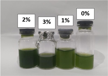
Figure 12. Retentates color at the end of the harvesting process at various addition of LiCl to the PVDF membrane.
Download figure:
Standard image High-resolution imageFigure 13 also showed the colour difference of microalgae retentates from the fifth minute to the fortieth minute on the PVDF/LiCl-2 membrane. The results show that the colour of microalgae gets darker with time. This was due to the decreasing amount of water in microalgae culture caused by filtering with membranes filtration.

Figure 13. Color difference of microalgae retentate during the first 40 min of PVDF/LiCl-2 membrane.
Download figure:
Standard image High-resolution image3.4. PVDF/LiCl membrane cleaning
3.4.1. Membrane performance after cleaning
The membrane used in cleaning was PVDF/LiCl-2 due to best performance in Nannochloropsis sp. harvesting. Membrane cleaning was carried out with a feed volume of 550 ml. Membrane was cleaned by sodium hypochlorite, citric acid, nitric acid solution, and combined cleaning of sodium hypochlorite and citric acid solution, also sodium hypochlorite nitric acid solution carried out for five cycles. The recovery flux was obtained as shown in figure 14.

Figure 14. PVDF/LiCl membrane flux recovery in some cleaning solution.
Download figure:
Standard image High-resolution imageThe membrane cleaning solution with the highest flux recovery in the first cycle was NaClO solution with a recovery of 99.67%. In the fifth cycle, membrane cleaning with NaClO solution decreased flux recovery up to 86.96%. In addition, membrane cleaning with NaClO followed by citric acid in the fifth cycle occured a slight decrease in flux recovery and resulted in a recovery of 89.40%. Meanwhile, membrane cleaning with citric acid and nitric acid only resulted in flux recovery of 82.35% and 80.38% in the fifth cycle, respectively. The results of the best flux recovery in membrane cleaning with NaClO solution in the first cycle showed that the foulant contained in the membrane were dominated by blockages originating from microalgae cells. While in the fifth cycle, membrane cleaning with NaClO followed by citric acid had the highest flux recovery. This result suggest that in harvesting process until the fifth cycle in addition to microalgae foulant, there is also salt foulant from microalgae media due to the long contact between the membrane and the microalgae feed solution. In research conducted by Ahmad et al [35] the use of NaClO for membrane cleaning in microalgae harvesting resulted in flux recovery up to 92% in the third cycle. Liang et al [56] also carried out the same cleaning with NaClO and resulted a flux recovery of 90.21% in once cleaning. NaClO in water on the membrane can hydrolyze rapidly to form hypochlorous acid (HOCl). HOCl oxidizes organic plugging functional groups into ketone, aldehyde, and carboxylic groups. This indicates that NaClO plays an important role in removing foulant in the membrane for microalgae harvesting. On the other hand, the combination of NaClO and citric acid cleaning had a higher effectiveness in membrane cleaning for microalgae harvesting. Not only removing organic foulant from microalgae cells, the combination of cleaning with citric acid also ensures the dissolution of inorganic complexes caused by seawater media from microalgae Nannochloropsis sp. In the study of Bilad et al [39] also reported that cleaning begins with immersion in NaClO, then continued with citric acid can remove blockages of membrane fouling. This result was confirmed from the SEM results, which showed that there were less aggregates in the membrane pores compared to membrane cleaning with NaClO only. On the other hand, the rejection of the membrane from the first to the fifth cycle obtained rejection of 100% in each cleaning solution. The results of the same rejection until the fifth cycle showed that the PVDF/LiCl membrane had good performance in separating microalgae on five times of use with repeated cleaning.
3.4.2. Membrane characteristic after cleaning
On the PVDF/LiCl membrane used for harvesting microalgae, there were several new bands that appeared due to the foulants layer on the membrane. The relative absorption peak at 3401 cm−1 is characteristic of the N-H hydrogen bond. In addition, there was also a typical amide absorption peak (C = O) at 1648 cm−1, which indicates the presence of a protein consisting of a chain of amino acid residues connected end to end by secondary amide bonds. This protein was produced from particulate microalgae cells that were fouled in the membrane pores. Meanwhile, the foulant originating from microalgae medium was not detected by FTIR because it was an inorganic salt foulant of seawater.
In the FTIR results of the cleaned membrane, there were several differences in the absorption peaks. The absorption peak of the membrane before cleaning at 1648 cm−1 was not detected on the membrane after cleaning. This is because NaClO can oxidize proteins and polysaccharides into ketone groups, aldehydes, and carboxylic groups, therefore remove them from the surface and pores of the membrane. On the other hand, citric acid can react with metal complexes that bind organic particulates into small molecules and metal ions [57]. In addition, the membrane cleaning with NaClO followed by citric acid showed differences in absorption with other membranes due to the dehydrofluorination reaction during cleaning. This dehydrofluorination process occurs in the PVDF polymer in an alkaline environment and was showed by the appearance of a lower absorption at 1654 cm−1, which indicates the presence of double carbons (C = C) [58]. Although the resulting intensity was very low, the PVDF/LiCl membrane showed a change in chemical composition when carried out with a cleaning combination of NaClO solution followed by citric acid (figure15(e)). The dehydrofluorinated membrane has a polar properties compared to the non-dehydrofluorinated membrane [59]. Therefore, the membrane that has been cleaned with NaClO followed by citric acid has a higher flux than the membrane cleaned with NaClO or citric acid only. The membranes cleaned with NaClO and citric acid only also did not show a carbonyl group peak (C = O) at around 1674–1680 cm−1 (figures 15(c) and (d)), which indicated that the membrane was no longer polar, thus the hydrophilicity of the PVDF/LiCl membrane decreased. The decrease in the hydrophilicity of the membrane was caused by the long cleaning time and the high concentration of NaClO [60]. In addition, the intensity of -CF2 stretching (1000–1100 cm−1) of the membrane after cleaning in the PVDF fingerprint became lower than the original membrane (before harvesting) (figure 15(a)). However, neither NaClO nor citric acid cleaning solution caused any damage to the chemical structure of the membrane [61] confirmed with the SEM results and rejection remained 100% until the fifth cycle. In addition, the absorption peaks on the membrane after cleaning with nitric acid and the combination of NaClO and nitric acid (figures 15(f) and (g)) did not occur significant changes compared with membrane before cleaning (figure 15(b)). This is due to the influence of NaClO and acid solution as a PVDF/LiCl membrane cleaning solution which functions to maintain the permeability and performance of the membrane, thus it does not decrease drastically in once use and can be used several times for the harvesting process of Nannochloropsis sp.

Figure 15. IR spectra of the membrane (a) before harvesting, (b) after harvesting (before cleaning), (c) after cleaning with NaClO, (d) after cleaning with citric acid, (e) after cleaning with NaClO followed by citric acid, (f) after cleaning with nitric acid, (g) after cleaning with NaClO followed by nitric acid.
Download figure:
Standard image High-resolution imageWhen compared with the membrane before harvesting (figure 16(a)), can be observed that there was a white clump on the membrane pores produced by particulates of Nannochloropsis sp. on the membrane after hervesting (figure 16(b)). These results indicate that the microalgae harvesting process can cause membrane fouling. PVDF/LiCl membrane, which has high hydrophilicity can attract algae particles, which also have hydrophilic properties, resulting membrane fouling. In addition, membrane fouling can occur due to pore blocking. As a result, it can block membrane filtration flow. The foulant particulates also make possibility to provide a gel matrix that is hydrated by other microorganisms embedded in the membrane [39]. Although the pore size of the membrane is smaller than the size of microalgae cells, the fouling that occurs can be caused by microalgae cells entering the finger-like porous and sticking to the macrovoids of the membrane, and clogging the sponge-like pore surface.

Figure 16. SEM results of PVDF/LiCl membrane (a) before harvesting (b) after harvesting (before cleaning) (c) after cleaning with NaClO followed by citric acid on the first cycle, (d) after cleaning with NaClO followed by citric acid on the fifth cycle, (e) after cleaning with NaClO followed by the nitric acid on the first cycle.
Download figure:
Standard image High-resolution imageOn the PVDF/LiCl membrane after the first cycle of cleaning (figures 16(c) and (d)), it was seen that the morphology of the membrane cross-section was not much different from the original membrane. Even though the membrane has been cleaned with NaClO followed by citric or nitric acid, the microalgae were not completely removed from the membrane. On the walls of the macrovoid membrane, there are few algae particles attached. This is consistent with the flux results obtained that the flux after cleaning is always lower than the flux before cleaning. This decrease flux did not affect the rejection result from the membrane after cleaning. Meanwhile, on the PVDF/LiCl membrane after the fifth cycle of cleaning (figure 16(e)) some algae particles adhering to the macrovoid walls were observed. In addition, there is also an agglomeration of algae particles that are in the pores of the membrane. Algae particles can obstruct the pores, thereby blocking the flow of filtration that enters the membrane [39]. Therefore, in the fifth cycle, a lower microalgae flux was obtained with the same rejection as at the begining of harvesting.
4. Discussion
4.1. Cultivation of Nannochloropsis sp.
The most important parameters regulating the algae growth was contamination culture medium, culture time, nutrients, and environmental conditions such as salinity, quantity of Sunlight and season. In this study, seawater and bottles used as culture media were sterilized by autoclaving at 121°C. This was conducted to prevent the contamination of other microorganisms that can interfere the growth of microalgae. In addition, the incubation process was carried out for 10 days. The incubation period of 10 days was the optimum time for microalgae cultivation. These results were explained in the study of Kwangdinata et al [62] that the fastest growth of Nannochloropsis sp. was found in the 3–10 day range, which was the exponential phase. Increased cell density was also enriched by the provision of nutrients in culture through fertilization. In this study, Walne medium was technically used as a nutrient source that contains a variety of micro macro nutrients, and vitamins for microalgae to grow [63]. Salinity affects the osmose pressure and osmoregulation mechanism that directly affect the metabolic process, respiration process and inhibit the process of vegetative cell culture in stages, thus that it will affect the density of microalgae populations [64]. Therefore, salinity of sea water as a growing medium for microalgae was controlled by a value of 28–32 ppt. Then, CO2 air flowed into the microalgae culture with sufficient lighting conditions will also be needed by the microalgae to photosynthesize. By controlling several important parameters, microalgae Nannochloropsis sp. successfully cultured by producing an average concentration of 0.594 g l−1.
4.2. Transferability of microalgae harvesting
Different species of algae have different cell sizes. This can affect the results of harvesting algae. However, this can be overcome by designing pore membranes. The membrane pores that are formed can be influenced by the composition of the polymer and solvent membranes. Besides that, it can also be done with membrane modifications such as adding additives. Microalgae of various species generally have a cell size of 3–30 μm. This size can be adjusted to the type of membrane used [2]. There are generally two types of filtration membranes, microfiltration (MF) and ultrafiltration (UF). The UF process is more desirable than MF in microalgae harvesting. The larger pores in MF make it easier to block the pores in the harvesting process. MF is usually attractive to large algae, because the larger size of the algae is more advantageous because it is easier to filter [65]. The PVDF/LiCl-2 membrane has an average pore diameter of 0.88 μm, so the microalgae cannot pass through the membrane as evidenced by 100% membrane rejection. The membrane prepared by the TIPS method did not suffer from permanent fouling even though it had a high molecular weight cut-off membrane. This may be due to the large hydrophilicity of the membrane. Algae release organic matter which is hydrophobic on the harvesting process. Thus, the results obtained can be explained because the stronger hydrophilicity of the TIPS membrane can increase the hydrophilic repulsion between the organic algal material and the membrane surface [2].
4.3. Membrane cleaning mechanism
The cleaning process on the membrane with NaClO, citric acid, and nitric acid has a different mechanism. Membrane cleaning with NaClO relates to cleaning with oxidant reagents, whereas membrane cleaning with citric acid and nitric acid was included in the type of cleaning with acid solution. The mechanism of membrane cleaning with NaClO following the Weerman degradation reaction (figure 17). In this mechanism, the amide in the protein plug is degraded in the presence of NaClO to form smaller groups such as aldehydes with a smaller number of carbons [66]. In the first step, the amide reacts with ClO− and forms HOCl. Nitrogen which has a free electron in the amide will attract Cl from HOCl. The electronegative OH ion then takes hydrogen in the amide and the Cl, which binds to the N will be released, resulting in the intermediate form of the OCN carbonyl, H2O and Cl− ions. This intermediate form will undergo rearrangement. Furthermore, hydrolysis of the OCN carbonyl occurs and a chain with an unstable acid amide is produced. This acid amide was released, resulting in an aldehyde form.

Figure 17. Illustration of cleaning mechanism on membrane cleaning with NaClO.
Download figure:
Standard image High-resolution imageIn the membrane cleaning mechanism with acid, there are two types of reactions at different types of foulants. In salt foulants from Nannochloropsis sp. medium, different types of salt will react with hydrogen ions from the ionization of citric acid in water. The reaction of the foulants with a type of carbonate salt produced metal ions along with CO2 and H2O. In addition, the foulants of sulfate and phosphate salts produced salt metal ions, sulfate and phosphate ions, and the formation of H+ ions. On the other hand, organic foulants that bind metal salts and form complexes reacts with H+ ions (figure 18). The reacting foulants produces smaller groups such as aldehydes and metal salt ions from the foulants complex [67].

Figure 18. Illustration of cleaning mechanism on membrane cleaning with acid.
Download figure:
Standard image High-resolution image
5. Conclusions
PVDF/LiCl membrane in this study succeeded in increasing the hydrophilicity revealed with water contact angle results, which increased from 82.23° ± 5.17 to 75.13° ± 5.08. The addition of LiCl was able to change the structure of the phase conformation from α to β, which has a high polarity. In this study, the PVDF/LiCl-2 membrane had a great microalgae harvesting performance. The water permeance value for PVDF/LiCl-2 membrane was 660 l m−2 h−1 bar-1, with an average value of microalgae permeance, which is 150 l m−2 h−1 bar−1 and a microalgae % rejection value of 100%. The membrane cleaning with NaClO followed by citric acid solution was the best cleaning compared to membrane cleaning using NaClO or citric acid and nitric acid solution only. The recovery of the membrane cleaning flux up to five cycles was 89.40% with a rejection of 100%. Membrane fouling occurs due to the presence of algae particles in the membrane pores. Microalgae foulant, which were dominated by the presence of amide groups were degraded through NaClO followed by acid solution cleaning. NaClO degrades foulants by following the Weerman degradation reaction mechanism, which converts foulants into smaller groups, while acid solution reacts on salt foulants and metal complexes that bind algae particles into smaller ions and compounds.
This work contributes to the development of PVDF flat-sheet membranes for the harvesting of microalgae. The results of this study are expected to be applied to the harvesting of microalgae in a large scale considering that algae biomass is very useful for alternative biofuel production. Whereas, the cleaning method can be used as reference for PVDF membranes cleaning on harvesting microalgae. Membrane cleaning can regenerate the membrane, so that it can be used repeatedly. In addition, this research can also provide information about the effect of the cleaning solution on the type of blockage that occurs in the membrane.
Acknowledgments
The authors desire to appreciate the research funding granted by the Ministry of Research and Higher Education of Indonesia, under 'Penelitian Dasar' (Fundamental Research) with contract no: 1508/PKS/ITS/2022.
Data availability statement
All data that support the findings of this study are included within the article (and any supplementary files).
Supplementary data (0.1 MB DOCX)
Supplementary data (0.1 MB DOCX)