

Abstract
This work reviews different techniques available for the synthesis and modification of cathode active material (CAM) particles used in Li-ion batteries. The synthesis techniques are analyzed in terms of processes involved and product particle structure. The knowledge gap in the process-particle structure relationship is identified. Many of these processes are employed in other similar industries; hence, parallel insights and knowledge transfer can be applied to battery materials. Here, we discuss examples of applications of different mechanistic models outside the battery literature and identify similar potential applications for the synthesis of CAMs. We propose that the widespread implementation of such mechanistic models will increase the understanding of the process-particle structure relationship. Such understanding will provide better control over the CAM synthesis technique and open doors to the precise tailoring of product particle morphologies favorable for enhanced electrochemical performance.
Export citation and abstract BibTeX RIS

Original content from this work may be used under the terms of the Creative Commons Attribution 4.0 license. Any further distribution of this work must maintain attribution to the author(s) and the title of the work, journal citation and DOI.
Abbreviations
| CAM | Cathode Active Material |
| NMC | Nickle Manganese Cobalt Oxide |
| NCA | Nickle Cobalt Aluminum Oxide |
| LNO | Lithium Nickel Oxide |
| LMO | Lithium Manganese Oxide |
| LNM | Lithium Nickel Manganese Oxide |
| LFP | Lithium Iron Phosphate |
| LCP | Lithium Cobalt Phosphate |
| LMP | Lithium Manganese Phosphate |
| LCO | Lithium Cobalt Oxide |
| LFS | Lithium Iron Silicate |
| TM | Transition Metal |
| CSTR | Continuous Stirred Tank Reactor |
| SD | Spray Drying |
| FSP | Flame Spray Pyrolysis |
| ALD | Atomic Layer Deposition |
| PP | Primary Particle |
| DoE | Design of Experiments |
| DFT | Density Functional Theory |
| MD | Molecular Dynamics |
| DEM | Discrete Element Method |
| PBM | Population Balance Modeling |
| PBE | Population Balance Equation |
| CFD | Computational Fluid Dynamics |
| MC | Monte Carlo |
| KLMC | Kinetic Lattice Monte Carlo |
| DSMC | Direct Simulation Monte Carlo |
| FEM | Finite Element Method |
| SDD | Single Droplet Drying |
| LLZO | Lithium Lanthanum Zirconium Oxide |
1. Introduction
With the increased awareness of global climate change and it is link to rising carbon dioxide emissions there is a tremendous interest in the decarbonization of transport through electrification. Due to their high specific capacities and long cycle lives, lithium-ion batteries are dominant technology in the field of electric mobility. Although a variety of new chemistries and battery architectures are being developed to push the limits of energy and power density, there is still room for improvement in the Li-ion battery first introduced by Sony in 1991 [1]. Apart from the specific chemistry, improvements in cost, performance, and recyclability can be achieved by better engineering and optimization of the cell manufacturing process [2]. An efficient manufacturing process is needed to meet the exponentially rising future demand for Li-ion batteries and to keep the cost of such devices competitive with incumbent and future technologies [3].
Starting from the synthesis of active materials to the module-level assembly of cells, many of the cell manufacturing processes are common to other industries. This review work focuses on the synthesis of intercalation type cathode active materials (CAMs) and various processes involved therein. For example, the widely used co-precipitation synthesis of CAM particles is also used for the production of various multi-constituent particles such as catalyst [4, 5], magnetic nano-particles [6–8], alloy systems [9]. Analytical and computational mechanistic models are often used in these industries to better understand the effect of various process parameters on the product particle properties.
Mechanistic models are based on mathematical equations governing the process. Although the governing equations could be derived from first-principles, some parameters can exhibit stochastic or phenomenological character. Analytical models find exact solution to relatively simple governing equations, while computational models are used to find an approximate solution to complex governing equations. Such mechanistic models prove useful for better understanding of the process-product relationship, increased process control and efficiency, improved equipment design, as well as effective scale-up.
Variety of intercalation type CAMs have been synthesized for Li-ion batteries. These can be classified into different categories (layered/spinel/olivine) based on the crystal structure [10–12]. Understanding the process-particle structure relationship during the synthesis is important for Li-ion batteries, as generated particle structures directly affect the electrochemical performance. Even for a fixed CAM chemistry, synthesis methods and generated particle structures affect the electrochemical performance including voltage profiles (figure 1(a)), rate capability (figure 1(b)), capacity retention (figure 1(c)), and columbic efficiency (figure 1(d)). More such quantitative comparison of electrochemical performance for different CAMs can be found in respective review works. Layered: NMC (LiNix Mny Co1-x-y O2) [13], NCA (LiNix Coy Al1-x-y O2) [14], LNO (LiNiO2) [15]; spinel: LMO (LiMn2O4) [16], LNM (LiNi0.5Mn1.5O4) [17, 18]; olivine: LFP (LiFePO4) [19, 20], LCP (LiCoPO4) [21], LMP (LiMnPO4) [22, 23].
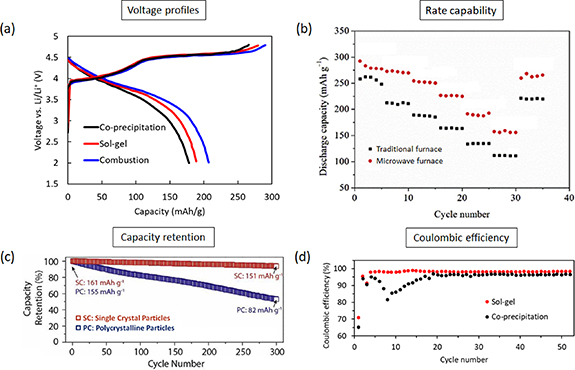
Figure 1. Effect of the synthesis method and particle structure on half-cell electrochemical performance. (a) First charge/discharge voltage profiles for Li, Mn rich NMC (Li1.2Ni0.13Mn0.54Co0.13O2) generated through three different synthesis techniques at 2 °C rate, Adapted from [25] Copyright (2011), with permission from Elsevier. (b) rate capability performance of Li, Mn rich NMC (Li1.2Mn0.56Ni0.16Co0.08O2) synthesized through calcination in the traditional vs microwave furnace at 900 °C, Adapted from [26] Copyright (2017), with permission from Elsevier. (c) capacity retention of single crystal NMC622 particles compared to polycrystalline particles at 1 C rate (180 mA g−1) in 4.3–2.8 V, Adapted from [27] Copyright (2020), with permission from Elsevier. (d) Coulombic efficiency for Li, Mn rich NMC (Li1.2Ni0.13Mn0.54Co0.13O2) synthesized through the sol-gel and co-precipitation route. Adapted from [24]. CC BY 4.0.
Download figure:
Standard image High-resolution imageThe pharmaceutical industry has benefitted by borrowing process monitoring and optimization knowledge from other industries [28, 29]. Various mechanistic models have been implemented to optimize the dry milling process in the pharmaceutical industry [30]. Whereas, successful applications of different mechanistic models in case of wet granulation can be found in the comprehensive review by Suresh et al [31]. Mechanistic models have proved useful for the scale-up of crystallization process [32]. Review by Kremer and Hancock [33] lists various example modeling applications in the pharmaceutical industry.
Similar implementation of mechanistic models is possible in the battery industry to optimize current CAM synthesis techniques. Keeping such knowledge transfer as the core theme, this review attempts to identify different processes involved in the CAM synthesis techniques, where similar mechanistic models can be potentially implemented. Section 2 discusses different synthesis techniques in terms of processes involved and product particle morphology. Conclusions from this discussion are drawn in section 3. Processes that are common to other industries are identified and respective mechanistic modeling studies available in the literature are discussed in section 4. Conclusions from the review of mechanistic modeling applications are drawn in section 5 along with potential applications in the CAM synthesis procedure. The review ends with section 6, where knowledge gaps in the CAM synthesis process-product relationship and potential applications of mechanistic models are re-iterated.
2. Synthesis techniques for the CAMs
Figure 2 schematically shows a typical microstructure of the two electrodes involved in a Li-ion cell. Both cathode and anode consist of multiple components: active material, conductive additives, and polymer binder. The conductive additives and polymer binder are shown as carbon-binder domain in the schematic for simplification.

Figure 2. Schematics depicting Li-ion cell and components of the electrode microstructure.
Download figure:
Standard image High-resolution imageThe CAM particles are made up of primary crystalline particles, conventionally 10–500 nm in size which form the secondary particles of 3–20 µm. Within these secondary particles, the primary particles (PPs) are fused together along grain boundaries. During the discharging of the cell, lithium-ions must intercalate into the CAM; this process begins with a charge transfer reaction at the interface of the CAM particle and lithium-ion containing electrolyte, followed by the migration of the ions within the crystal structure. This process is reversed during charging. The particle-scale electrochemical performance depends on factors like rate of Li-ion diffusion, active surface area, electrolyte penetration, and structural strength of the secondary particle. These factors vary based on the secondary particle chemistry, morphology, and synthesis technique.
In an effort to improve the electrochemical performance, researchers have endeavored to synthesize variety of CAM particle morphologies. Multiple review works in the literature contain detailed discussion on the synthesis techniques, resulting particle morphologies, and electrochemical performance [11, 13–15, 19, 21, 34–39]. Hence a quantitative comparison of the electrochemical performance is avoided in current review.
Significantly different morphologies are obtained by modifying the synthesis procedure. Distinctly different synthesis techniques are discussed in this section. All of these synthesis techniques are multi-step procedures and as such are energy and time expensive [40]. Following subsections outline different synthesis techniques in approximately ascending order of complexity and provide an array of representative examples where the technique has been used to generate different particle morphologies. The studies often do not investigate the effect of process parameters on product particle morphologies. Many of these distinct morphologies have been found to improve the electrochemical performance.
2.1. Solid state and molten salt synthesis
As the name suggests, in solid-state synthesis the raw material is used in a solid powder form. Solid-state synthesis is relatively simple, efficient, and scalable synthesis technique. In this process, the precursors are firstly mixed and ground thoroughly, then heated to decompose the precursors and expel the gases [21]. The Li2CO3 and Co3O4 powder mixture is calcined, reground, and sintered again to form the final LCO (LiCoO2) particles (figure 3(a)) [41, 42]. Well-shaped crystals of NMC111 (Li[Ni0.33Co0.33Mn0.33]O2) with sharp edges were obtained through solid-state synthesis of transition metal (TM) acetate salts (figure 3(b)) [43]. Mostly chains of PPs are formed through this synthesis technique.

Figure 3. Variety of secondary particle morphologies generated through solid-state and molten-salt synthesis. (a) LCO particles generated through solid-state synthesis, Adapted from [41] Copyright (2016), with permission from Elsevier. (b) NMC particles generated through solid state synthesis, Adapted from [43] Copyright (2004), with permission from Elsevier. (c) Polyhedron shaped NMC particles generated through molten salt synthesis. Adapted from [54] Copyright (2017), with permission from Elsevier.
Download figure:
Standard image High-resolution imageSolid-state route is widely applied for synthesizing phosphate based LFP [19, 20] and LCP [21]. Similar solid state route has been employed to synthesize orhtosilicate LFS (LiFeSO4) [44, 45] and LiFeSO4/C composite [46, 47]. In LiFeSO4/C composite a carbon source (sucrose/carbon/coal pitch/carbon nanotube) is added during the grounding and calcination step. Different compositions of Li2Fe1−x Cox /2Mnx /2SiO4 were prepared through rapid solid state synthesis [48]. Solid state synthesis is also employed to generate other promising CAMs such as layered: LNO [15], NCA [14], single crystal NMC622 [49]; spinel: LMO [16], LNM [17, 18, 50]; and tavorite: Li2CoPO4F [51], NaLiFePO4F [52].
In molten salt synthesis, the raw material powders are melted near their eutectic temperatures. Han et al [53] melted the LiCl, Li2CO3, and CoCl2 powders in a muffle furnace to synthesize LCO. Whereas, Polyhedron shaped PPs of NMC111 were obtained through a the molten salt technique (figure 3(c)) [54]. The NMC111 hydroxide precursor was obtained through the co-precipitation synthesis (section 2.3). The solid precursor was then mixed with molten lithium salt and calcined to obtain the final product. Similarly, molten salts of Li2CO3, Na2CO3, and K2CO3 were mixed to obtain (Li0.435Na0.315K0.25)2CO3. This carbonate mixture was ball-milled with iron source (FeC2O4 · 2H2O), Li2SiO3. After drying and heat treatment Li2FeSO4 was obtained [55]. Molten salt synthesis has also been used for generating layered: single crystal NMC particles [27, 56]; spinel: LNM [17, 18, 50]; and olivine: LFP/C composites [57].
2.2. Sol-gel synthesis
The sol–gel process is advantageous over solid state synthesis due to low temperature, good homogeneity, and high purity [21, 50]. In sol-gel a gelling agent is added to the reactor and the solution is heated to obtain the precursor gel. Tang et al dissolved lithium, cobalt acetates into water and added citric acid to the solution. The solution was heated to obtain a transparent gel. The gel was dried, grounded, and the powders calcined to obtain the final LCO nanoparticles product (figure 4(a)) [58]. Shaju and Bruce obtained macro porous NMC particles synthesized through a one-step sol-gel route [59]. Heating during the precursor precipitation generates viscous gel which is then dried, ground, mixed with Li2CO3, and calcined to obtain the final product. Type of gelling agent (citric acid, glycine, starch, gelatin) was found to affect the LCO particles synthesized through the sol-gel route (figure 4(b)) [60]. Chains of NMC111 PPs were obtained by using table sugar as the chelating agent during the sol-gel synthesis (figure 4(c)) [61].

Figure 4. Variety of secondary particle morphologies generated through sol-gel synthesis. (a) LCO nano-particles with citric acid as the gelling agent, Adapted from [58] Copyright (2010), with permission from Elsevier. (b) LCO particle with starch as gelling agent, Adapted from [60]. CC BY 4.0. (c) Chains of NMC111 with table sugar as gelling agent. Adapted from [61] Copyright (2013), with permission from Elsevier.
Download figure:
Standard image High-resolution imageSol-gel based synthesis of LFP [19, 20] and LCP [21] has been collated. It is emphasized that different parameters of the sol-gel synthesis such as precursors, sintering temperature and time had significant effect on the electrochemical performance. Other CAMs including layered: LNO [15], NCA [14]; spinel: LMO [16, 62], LNM [17, 18, 50]; orthosilicate: LFS, LiFeSO4/C [63, 64]; and tavorite: Li2CoPO4F/C [65] have also been generated through the sol-gel route.
2.3. The co-precipitation synthesis
The co-precipitation synthesis is commonly used in industrial production of CAM particles [66, 67]. Different materials such as NMC, NCA have been synthesized through the co-precipitation technique. Figure 5 shows a schematic representation of this synthesis procedure.

Figure 5. The Co-precipitation synthesis route. Adapted from [66] Copyright (2017), with permission from Elsevier.
Download figure:
Standard image High-resolution imageThere are multiple variants of the co-precipitation technique. But following steps are common to all. The synthesis starts with aqueous solution of TM salts, suitable precipitating agent, and chelating agent. These raw materials are added and mixed in a continuous stirred tank reactor. The proportions of the raw materials are carefully controlled. Appropriate pH level and temperature is maintained in the reactor. Desirable stirring speed, stirring duration, and reactor atmosphere (N2 or O2 or air) is selected. The precipitated precursor is filtered, washed, and dried. Next step involves lithiation and decomposition of the precursor into final product. The lithiation step is a solid state reaction process. The precursor powders are ground in a mortar or milled in a ball-mill and mixed with a lithiating agent. This mixture is heat treated (calcination or annealing or sintering) to obtain the final CAM product.
Noh et al demonstrated that the PP shape depends on the specific NMC composition Li[Nix Coy Mnz ]O2 [68]. Decreasing PP size was obtained with increasing Ni content, while surface rough and non-spherical secondary particles were synthesized through co-precipitation. Process parameters like concentrations, pH, temperature, and stirring speed were observed to affect the secondary particle morphology.
Yang et al [69], employed the co-precipitation technique to generate NMC111 hydroxide precursors. Emphasis was placed on the growth analysis of the precursor agglomerates. As the precursor shape largely determines the shape and structure of final CAM particles, such insight in formation and growth of precursors can be used to optimize the synthesis process through use of mechanistic models discussed in section 4. Co-precipitation was employed to generate phase-pure well-ordered Li[Li0.2Ni0.2Mn0.6]O2 CAM particles with average size of 20 µm and narrow size distribution [70]. Initially irregular precursor particles transformed into smooth porous spheres during vigorous stirring in the reactor. As seen in figures 6(a) and (b), distinct secondary particle morphologies of Ni-rich NMC with radially and randomly-aligned PPs were obtained after calcination of precursors obtained from two different suppliers (Shuangdeng Group Co, Ltd and Argonne National Laboratory) [71]. Little explanation was provided for this phenomenon.

Figure 6. Variety of secondary particle morphologies generated through co-precipitation. (a) Radially-aligned primary particles of Ni-rich NMC, Adapted from [71]. CC BY 4.0. (b) Randomly-aligned primary particles of Ni-rich NMC, Adapted from [71]. CC BY 4.0. (c) Core–shell structure, Adapted with permission from [72]. Copyright (2005) American Chemical Society. (d) Core-concentration gradient shell structure, Adapted from [73] John Wiley & Sons. Copyright © 2010 WILEY-VCH Verlag GmbH & Co. KGaA, Weinheim. (e) Structure generated through high shear reactor, Adapted from [77] Copyright (2020), with permission from Elsevier. (f) Single crystals of NMC622. Adapted from [82]. CC BY 4.0.
Download figure:
Standard image High-resolution imageFew studies deviate from this traditional co-precipitation technique and report distinctly different particle structures. Sun et al modified the addition sequence of the TM metal salts in the stirred tank. Instead of adding stoichiometric amounts of TMs simultaneously, the Ni-rich solution was added first then subsequently Ni-poor solution was added to generate the core–shell particle structure (figure 6(c)) [72]. Such core–shell synthesis examples of layered, spinel, olivine CAMs have been collated along with respective electrochemical performance data [34]. Other variants of this technique include core-concentration gradient shell structure (figure 6(d)) [73] and the full concentration gradient structure [74]. It is important to note that these significantly different structures were resulted by modifying the addition sequence of the TM salts in the reactor. Noh et al applied similar technique and demonstrated significant difference in particle morphology arising from spatially uniform or variable concentration of TMs [75]. The secondary particles consisted of radially aligned nano-rod PPs for the variable concentration of TM salts.
As shown in figure 6(e), hierarchical porous secondary particles have been generated consisting well-aligned faceted PPs for three different chemistries: LiNi1/3Co1/3Mn1/3O2, LiNi0.6Co0.2Mn0.2O2, Li1.2Ni0.2Mn0.6O2 [76]. These morphologies were possible due to use of a high shear reactor in place of the traditional stirred tank. The generated flow field causes exfoliation of the particles creating faceted nano-plates. Such faceted PP structure helps rapid migration of Li-ions resulting in improved electrochemical performance. A later study combined the high shear reactor with sequential addition of TM solutions to generate core–shell NMC523 particles with a void layer between the core and the shell [77]. Zhu et al synthesized four different secondary particle morphologies of Ni0.6Co0.2Mn0.2(OH)2 by using four different impeller types (propeller turbine, pitched blade turbine, flat blade turbine, Rushton turbine) [78]. Morphologies varied from spherical dense secondary particles to particles made up of flat and flaky PPs. The difference in the morphologies was explained based on different flow fields generated by varying impeller geometries.
Distinct approach using microemulsion based co-precipitation was employed to synthesize single crystals of spinel LNM [79]. Oil-in-water emulsion was used as in-situ co-precipitation site. Aqueous solution of Nickel and Manganese acetates was poured in kerosene oil under stirring to generate microemulsions. Emulsions were stabilized with non-ionic surfactants. This emulsion was dropped into the aqueous solution of the NH4HCO3. Due to emulsification single crystals of Ni0.5Mn0.5(CO3)2 precursor are generated. After grounding with lithiating agent, pelletizing, and sintering single crystals of LiNi0.5Mn1.5O4 are obtained.
Co-precipitation has also been used to generate other CAMs including layered: LiNi0.5Mn0.5O2 [80], LNO [15], NCA [14]; spinel: LMO [16], LNM [17, 18, 50, 81]; and olivine: LFP [19, 20]. Single crystal morphologies (figure 6(f)) of high-Ni CAMs can be generated through milling and high temperature sintering of precursors obtained through the co-precipitation route [82, 83].
From these studies it can be concluded that variety of factors in the synthesis technique affect the final particle morphology during co-precipitation. These include the choice of TM salts, precipitating agents, chelating agents that affect the precursor morphology. The proportions of the starting materials have a significant effect on the final product structure and properties. Figure 6 collates different secondary particle morphologies generated through co-precipitation. More exhaustive comparison of precursor particle structures synthesized through co-precipitation can be found elsewhere [84].
2.4. Self and sacrificial template synthesis
In the self and sacrificial template synthesis method, the co-precipitation technique is followed to obtain a precursor containing a different composition of TMs compared to the composition in final product. The porous precursor is used as a template and desired composition of TMs is achieved during the grounding step.
Uniquely structured particles of NMC111 comprising of nano-sized PPs were generated through a facile template sacrifice as shown in figure 7(a) [85]. MnO2 microspheres were generated after sintering of the MnCO3 precursor. Ni and Co nitrate solutions were sequentially added to the solution containing MnO2 microspheres under stirring to obtain the final NMC111 particles. Wu et al obtained cube shaped hierarchical NMC111 particles through self-template synthesis (figure 7(b)) [86]. First, the cube shaped MnO2 particles were obtained via precipitation of carbonate precursor and further annealing. These cubes were dissolved in Ni, Co nitrates with LiOH in ethanol. After evaporation the mixture was ground and calcinated to obtain final product particles. Chen et al used silver nitrate as a catalyst in the precipitation process to obtain spherical fluffy MnO2 particles [87]. Subsequently other TMs were added to obtain the final particles containing fluffy MnO2 at the core surrounded by short nano-wires. In another study, CaCO3 was used as sacrificial template to obtain porous spherical size NMC111 particles [88]. The CaMn3(CO3)4 precursor was calcined to obtain MnO2-CaCO3. The CaCO3 was removed to obtain nano-porous MnO2 spheres. Similar process as above was followed to obtain the final NMC111 particles (figure 7(c)). Template synthesis is also used for single crystal nanowires of spinel LMO [89] and olivine LFP/C composite [90].
Figure 7. Variety of secondary particle morphologies generated through template synthesis. (a) NMC111 secondary particles consisting nanometer size primary particles, Adapted from [85] Copyright (2014), with permission from Elsevier. (b) Cube shaped NMC particle generated from cube shaped MnO2 particle, Adapted from [86] with permission from the Royal Society of Chemistry. (c) NMC particle generated from nano-porous MnO2 sphere. Adapted from [88], with permission from Springer Nature.
Download figure:
Standard image High-resolution image2.5. Combustion and thermal synthesis
Combustion and thermal synthesis techniques involve high temperature heating of TM salt mixtures. Riley et al synthesized irregular chains of PPs through combustion synthesis [91]. The TM nitrates were melted together then the mixture was allowed to cool down and solidify. After grounding, the powder was mixed with sucrose and water to make a thick red syrup. This mixture was then combusted to obtain the final product. Sucrose-aided combustion method was used to obtain tavorite Li2CoPO4F [92]. LiCoPO4 was first generated from aqueous solutions of LiNO3, Co(NO3)2 · 6H2O, and NH4H2PO4. Milling, pelletizing, and annealing of LiCoPO4 and LiF was followed to obtain final Li2CoPO4F. Combustion synthesis has also been used for synthesizing spinel LMO [16], LNM [17, 93].
The solvo/hydro thermal synthesis involves heating of the TM salts solution in autoclave. The precursors are dissolved and mixed in solvents, then sealed in an autoclave to react at temperature above the boiling point of the solvent [21]. Ryu et al dissolved the TM acetates and urea in water [94]. Ethylene glycol was also added to the mixture. After continuous stirring, the mixture was annealed in autoclave. Remaining steps to obtain the final product are similar to the co-precipitation route. This solvo/hydrothermal method generates distinctly shaped secondary particles. For example, 3D dumbbells assembled from nano-cubes (figure 8(a)) [94] and peanut-like secondary particles (figure 8(b)) [95].

Figure 8. Variety of secondary particle morphologies generated through solvo/hydro thermal synthesis. (a) Dumbbell shaped NMC particle generated through solvo thermal synthesis, Adapted from [94] Copyright (2014), with permission from Elsevier. (b) Peanut-shaped NMC particle generated through solvo thermal synthesis, Adapted from [95] Copyright (2020), with permission from Elsevier. (c) Yolk-shell secondary particle generated through hydro thermal synthesis. Adapted from [96] with permission from the Royal Society of Chemistry.
Download figure:
Standard image High-resolution imageTM acetates were heated in autoclave to obtain a precursor. Due to different densification of the inner core and outer shell of the particle, two types of pore sizes were observed. This particle was termed to have hierarchical porous yolk-shell like architecture (figure 8(c)) [96]. The void between the yolk and the shell is speculated to be due to the heterogeneous contraction caused by non-equilibrium heating.
Hydro/solvo-thermal synthesis is also used for other CAMs including layered: NCA [14]; spinel: LMO [16], LNM [97]; olivine: LFP [19, 20, 98, 99], LFP/C nano-plates [100], LCP [21, 101]; and tavorite: Li2CoPO4F [102] production.
Microwave heating is advantageous in achieving fast uniform heating of the sample. Microwave heating has been used for the mixture annealing step to generate LiFe1-x Mnx PO4 particles [103]. Depending on the Mn content, high aspect ratio PPs were assembled into flower like secondary particles. Similar microwave synthesis has been employed to generate layered: NMC811 [104], Li1.2Mn0.56Ni0.16Co0.08O2 [26, 105]; spinel: LNM [106]; olivine: LFP [19, 20], LCP [21]; and orthosilicate: LFS [107].
2.6. Spray drying (SD) and flame spray pyrolysis (FSP) synthesis
SD and FSP technique offer an alternative to the reactor-based synthesis. The lithium and TM salts in aqueous form are pumped into a spray nozzle and the sprayed droplets are dried to obtain the precursor. The precursor is then annealed to obtain the final product. Different examples of spray-dried active material particles and corresponding electrochemical performance have been collated [108].
Crumbling agglomerates and chains of NMC111 PPs were obtained through spray drying (figure 9(a)) [43]. Wang et al demonstrated that preheating of metal salt mixture before spray drying and final heating generates good spherical secondary particles of Mn-rich NMC (Li[Li0.2Mn0.54Ni0.13Co0.13]O2) with enhanced electrochemical performance compared to spray dried particles generated without preheating of metal salt mixture (figures 9(b) and (c)) [109].

Figure 9. Variety of secondary particle morphologies generated through spray drying and flame spray pyrolysis. (a) Crumbling NMC111 morphology obtained through spray drying, Adapted from [43] Copyright (2004), with permission from Elsevier. (b) Spray dried Mn-rich NMC particle obtained without preheating of the powder mixture, (c) Spray dried Mn-rich NMC particle obtained with preheating of the powder mixture, Adapted from [109] Copyright (2017), with permission from Elsevier. (d) NMC111 secondary particle obtained through flame spray pyrolysis, Adapted from [40]. CC BY 4.0. (e) Spray dried NCA particle with rough surface, (f) Flame Spray Pyrolyzed NCA particle showcasing smooth surface. Adapted from [111] Copyright (2020), with permission from Elsevier.
Download figure:
Standard image High-resolution imageThe TMs were found to segregate during a spray-pyrolysis synthesis [110]. Spherical NMC442 secondary particles (5–20 µm) had Ni-poor and Mn-rich surfaces. This local migration of elements was observed to be mostly dependent on the thermal annealing process. Fröhlich et al obtained secondary agglomerates consisting nanometer scale round PPs of NMC111 through the flame spray pyrolysis synthesis (figure 9(d)) [40]. TM chlorides were sprayed in a roasting chamber to obtain the intermediate product of large hollow spheres with faceted PPs. After ball-milling during the lithiation step, roughly round secondary particles were obtained.
Zhang et al compared the morphology of the NCA (LiNi0.8Co0.15Al0.05O2) secondary particles synthesized through the SD and FSP technique [111]. The SD generated large hollow spheres with rough surface (figure 9(e)) while the FSP produced small size particles with relatively smooth surface (figure 9(f)). Along with layered CAMs, spray pyrolysis has also been used for synthesizing spinel: LMO [16], LNM [17, 18], and olivine: LFP [112, 113], LCP [23], LMP [22, 114] CAMs.
2.7. Doping, coating, and post-processing
Doping of NMC particles with small amounts of dopants has been shown to affect the secondary particle morphology. As shown in figure 10(a), Nguyen et al demonstrated a secondary particle comprising of radially-aligned PP obtained from 0.3% molar doping of Sn in high-Ni NCM [115]. It is observed that different dopants alter the secondary particle structure differently. For doping, the traditional co-precipitation is followed until the lithiation step. A doping agent is added to the precursor along with the lithiating agent during grounding in mortar or milling in ball-mill. After calcination, the particle morphology is significantly altered due to the doping agent. The resulting secondary particle structures were found to be beneficial in resisting micro-cracks and thus improving the degradation performance [116].

Figure 10. Variety of post-processing techniques. (a) Sn doping to generate secondary particles containing radially aligned primary particles, Adapted from [115] Copyright (2021), with permission from Elsevier. (b) Dry mechanofusion based coating of Al2O3 on CAM particle, Adapted from [122] Copyright (2019), with permission from Elsevier. (c) Nano-structured secondary particle generated by further ball milling, spray drying, and sintering of as received NMC particles. Reproduced from [125]. © The Author(s) 2018. Published by ECS. CC BY-NC-ND 4.0.
Download figure:
Standard image High-resolution imageNano-particle coatings are effective in improving structural stability and cycling performance of micron-sized CAM particles. Different coating materials like Al2O3 [91, 117, 118], LiAlO2 [119], CeO2 [120], ZnO [121], ZrO2 [121] have been coated on the surface of CAM particles through the sol-gel [119], dry mechanofusion (figure 10(b)) [122], and ALD [123, 124] techniques. ALD has advantages over other coating methods in terms of regulating film thickness in the Angstrom range, allowing a uniform coating and good conformality [124]. Studies investigating effect of ALD coatings on the electrochemical performance have been collated [123, 124].
Dreizler et al and Wagner et al performed further post-processing of commercially synthesized NMC111 particles by milling to generate nano-particles, then spray drying and sintering to obtain final porous nano-structured particles (figure 10(c)) [125, 126]. Single crystal morphologies have been generated by further milling, high temperature annealing of polycrystalline CAM particles [56, 127].
3. Conclusions from the CAM synthesis techniques
Table 1 below summarizes different synthesis techniques, corresponding advantages, disadvantages, and CAM chemistries that can be synthesized through a given technique.
Table 1. Comparison of different synthesis techniques in terms of advantages, disadvantages, and example CAM chemistries synthesized.
| Synthesis technique | Advantages | Disadvantages | Synthesizes CAMs |
|---|---|---|---|
| Solid-state |
|
| Layered: LCO [41, 42], NMC [43], NCA [14], LNO [15], Single crystal NMC [49] Spinel: LMO [16], LNM [17, 18, 50] Olivine: LFP [19, 20], LCP [21] |
| Molten salt |
|
| Layered: LCO [53], NMC [54], NCA [128], Single crystal NMC [56] Spinel: LNM [17, 18, 50]. Olivine: LFP [57] |
| Sol-gel |
|
| Layered: LCO [58, 60] NMC [59, 61], LNO [15], NCA [14]. Spinel: LMO [16, 62], LNM [17, 18, 50]. Olivine: LFP [19, 20], LCP [21, 65] |
| Co-precipitation |
|
| Layered: NMC [68–78], LNO [15], NCA [14], Single crystal NMC [27, 82, 83]. Spinel: LMO [16], LNM [17, 18, 50, 79]. Olivine: LFP [19, 20]. |
| Hydro/Solvo thermal |
|
| Layered: NMC [94–96], NCA [14] Spinel: LMP [16], LNM [97] Olivine: LFP [19, 20, 98–100], LCP [21, 101, 102] |
| Microwave |
|
| Layered: NMC [104], Li1.2Mn0.56Ni0.16Co0.08O2 [26, 105] Spinel: LNM [106] Olivine: LiFe1-xMnxPO4 [103], LFP [19, 20], LCP [21] |
| Spray based |
|
| Layered: NMC [40, 43, 109, 110], NCA [14, 111, 129] Spinel: LMO [16], LNM [17, 18, 50] Olivine: LFP [112, 113], LCP [23], LMP [22, 114] |
From the table it can be observed that all of the synthesis techniques are capable of synthesizing CAMs of varying structures (layered/spinel/olivine). The differences are in terms of process simplicity, cost, scalability, and particle properties (crystallinity, homogeneity, and PSD). Suitability of a synthesis technique for generating given CAM chemistry should be determined through consideration of these factors. It should be noted that common synthesis techniques are discussed in this section. While variety of other techniques like freeze drying, polymer-assisted, mechano-chemical, combinational annealing, electrospinning, phase inversion, supercritical fluid, ionothermal, biosynthesis exist in the literature [16, 17, 23, 37, 50].
Different synthesis techniques discussed previously can be compiled together as shown in figure 11. Variety of options are available at each stage along the synthesis procedure. Different synthesis techniques can be explored by selecting one of the available options at each step. Some steps like filtration, washing, drying, grounding are common to all synthesis techniques.
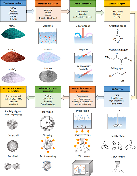
Figure 11. Summary of cathode active material synthesis techniques. Multiple options are available at each stage along the synthesis route. Product particle structure depends on specific set of options selected at each stage.
Download figure:
Standard image High-resolution imageEach technique thus constructed can potentially generate a different CAM secondary particle structure. Moreover, the proportions of materials involved, and the equipment operating parameters influence the particle structures. Often, a slight change in the synthesis procedure generates significantly different particle structures. For example, simultaneous addition of TM salts in the reactor generates spherical secondary particles with uniform composition, while stepwise addition of the TM salts generates core–shell structure. Readers interested in the comparison of electrochemical performance of cells made from different CAM particle structures should refer to respective review studies [34–37, 39].
Distinct product particle structures are often not pre-determined but are produced due to the specific combination of the process parameters along the synthesis route. A mechanistic understanding of the process-particle structure relationship is lacking. Hence, given a synthesis technique along with process parameters, it is difficult to predict the final particle structure beforehand. Lack of understanding about how different process parameters affect the structure can result in significant product variability and poor process optimization [28, 29]. Dong and Koenig emphasized on detailed understanding and investigations into the fundamental mechanisms behind the synthesis of precursors obtained through the co-precipitation synthesis [84]. Such understanding is needed to realize the full potential of the synthesis techniques in generating a large array of different particle structures.
Very few studies in the battery literature investigate the effect of process parameters on the product properties through the use of mechanistic models. As mentioned in the introduction, some of these processes are widely used in other industries. Multiple studies related to the understanding of the process-product relationship through the use of mechanistic models exist in respective literature. Next section identifies such common processes. Example mechanistic modeling studies for each of these processes are discussed and potential applications to the CAM synthesis are identified.
4. Mechanistic modeling
The CAM synthesis techniques involve different processes like reactive precipitation, spray drying, flame spray pyrolysis, milling, calcination/sintering, and coating. Resulting product particle structures depend on the specific raw material properties. Even for the same raw materials, process parameters such as the equipment design, operating parameters, scale-up can also influence the product particle properties. Often this process-product relationship is investigated through vigorous experimentation. Data obtained from such experimental campaign is used to build predictive correlations between process parameters and product properties. Such data-driven methods include DoE, empirical correlations, and machine learning algorithms. Mechanistic models can substantially eliminate this need for vigorous experimentation. This section focuses on such mechanistic models.
Mechanistic models are based on mathematical equations governing the process. For first-principle based mechanistic models, all required input parameters can be calculated. While, input parameters involved in some mechanistic models need to be obtained from experimental measurements or data-fitting based calibration. For some processes, exact solution to the governing equation can be obtained analytically. Resulting in an analytical model. For most of the processes, approximate solutions are obtained through the application of a variety of computational methods. This section focuses on the process-product relationship predicted by the mechanistic models, rather than detailed explanation of the governing equations and solution methods. Brief definitions of commonly used mechanistic models (atomistic to macro-scale) along with introductory references are provided next.
Density functional theory (DFT): DFT is an approach to finding solution to the Schrödinger equation governing quantum behavior of atoms and molecules. In computational chemistry, DFT is useful in first-principle based calculation of material properties such as lattice constants, surface energies, structural energies, elastic constants [130, 131]. For detailed information on DFT readers are referred to introductory texts [132, 133].
Molecular dynamics (MD): MD simulation consists of numerical, step-by-step, solution of the classical equations of motion. This model is useful for computationally simulating the movements of atoms and molecules. Interactions between atoms/molecules are determined based on acting forces. The forces are derived from potential energy which in turn depends on interatomic potentials. Atomistic MD simulations are useful in determining atomic/molecular interactions during a process. Detailed information about MD can be found elsewhere [134, 135].
Phase field method: The phase field method is particularly useful in simulating changes in material microstructure comprising grains. The grain morphologies are represented through phase field variables. Temporal evolution of the phase field variables is governed by a set of partial differential equations. This model can predict evolution of grains due to different driving forces (bulk and interfacial energy, elastic energy, electric or magnetic energy) and transport processes (mass diffusion, heat conduction and convection). Detailed explanation and applications of the phase field method can be found elsewhere [136–138].
Discrete element method (DEM): DEM proves useful in accurate simulations of processes dominated by inter-particle interactions. Since the inception of DEM by Cundall and Strack [139], it has been widely used to simulate particulate processes. Similar to MD, particle trajectories are calculated based on equations of motion. Contact forces generated due to numerous inter-particle interactions are calculated during the process. With increasing number of particles and complex particle shape, computational cost of DEM also increases.
Population balance modelling (PBM): PBM is widely used to describe temporal evolution of population of particles during a process. The governing PBEs define how populations of separate entities develop in specific properties over time. The integro-differential equations are essentially a balance on number of particles of particular state. Detailed information about the derivation of PBEs, applications, and limitations can be found in respective literature [140].
Computational fluid dynamics (CFD): CFD is indispensable when motion of fluid is of interest. At fundamental level, the governing Navier–Stokes equation describes the motion of viscous fluid and is derived from the conservation of mas and momentum [141]. Variety of computational methods have been developed to find solution to the Navier–Stokes equation for different fluid flows. Enormous literature exists on application, variants, computational cost, and limitations of CFD [142].
Monte carlo methods (MC): MC methods represent a broad class of models relying on repeated random sampling and statistical analysis to compute the results. Random samples from a probability distribution of input parameters are generated and corresponding outcome is predicted based on an underlying mechanism [143, 144]. Variants of MC models include the KLMC and DSMC. KLMC deals with determining dynamic evolution of atoms in a lattice structure [145]. DSMC is used for fluid dynamics simulations in the free molecular regime. Due to dominant molecular effects, Boltzmann equation of kinetic theory governs the flow instead continuum Navier–Stokes equation. Since its inception by Bird [146], DSMC has been continually developed for simulating dilute non-continuum gas flows [147, 148].
Based on the extent of the simplifying assumptions behind the governing equations, mechanistic models can have limited applicability. Multiple mechanistic models are often need to be coupled together (DFT-Phase Field Method, CFD-PBM, CFD-DEM) to develop a comprehensive multi-scale model representing the complete process under consideration. Rantanen and Khinast presented a review of different process modeling tools available for the pharmaceutical manufacturing process with emphasis on how different tools can be coupled to each other for increased fundamental process understanding [29]. A thorough validation of the developed model is required for accurate quantitative predictions about the process-product relationship. It is important to note that even if models have limited accuracy, they can prove useful in improving the fundamental scientific understanding of the process [29]. Such increased understanding enables optimization, control, and scale-up of the processes.
Very few studies in the Li-ion battery literature employ mechanistic process modeling tools. Many of the processes involved in CAM synthesis are common to other industries like pharmaceutical, dairy, minerals, ceramic, nuclear, cement, micro-electronics industry. Multiple studies investigating process-product relationship based on mechanistic models exist in respective literature. Similar models can be imported in the battery industry. Following subsections discuss representative mechanistic modeling studies for different processes. Emphasis is placed on the conclusions drawn about the process-product relationship rather than a detailed explanation of the mechanistic model employed. The section is concluded by identifying potential mechanistic modeling applications to the CAM synthesis procedures.
4.1. Crystallization and precipitation in stirred tank
Crystallization and precipitation is an integral part of the co-precipitation synthesis route. Experimental investigations related to effect of process parameters on CAM particle properties synthesized through co-precipitation have been collated [13, 84].
Few studies in the battery literature apply mechanistic models to investigate the process-product relationship during co-precipitation synthesis [131, 149]. These studies focus on the precipitation process inside a reactor and employ a combination of mechanistic models. A multi-scale mechanistic model simulating the nucleation, growth, and aggregation of particles during co-precipitation of NMC111 hydroxide precursors has been developed [149]. The classical nucleation theory determines the initial number density of the nuclei. Further growth of these PPs is modeled through a continuum growth model based on population balance equations accounting for diffusion of reactants through the solution and precipitation on the particle surface. For aggregation of PPs into secondary particles, lattice based MC method is employed. This multi-scale model predicts that increasing solution pH and decreasing ammonia concentration leads to smaller secondary particle size. The model is then used to perform parametric study and identify optimal parameter values to obtain uniformly sized secondary particles. Although co-precipitation of NMC111 particles was simulated, the computational framework is promising and can be employed to other co-precipitation systems. The model could be used to tune the secondary particle size by controlling the solution pH and ammonia concentration. Few limitations exist in this multi-scale model. The PPs are assumed spherical; thus the internal porosity of the secondary particle cannot be captured. Leading to a bad tap density prediction. Effect of stirrer speed on the particle morphology is not captured. The model focuses on predicting the size of precipitated precursors. The particle morphology can change during the lithiation/calcination step. Model could be developed further to include the effect of calcination on particle size and shape.
A predictive mechanistic model combining the DFT and phase field method is developed for investigating the effect of process parameters on shape of the MnCO3 precipitates [131]. It is predicted that with increasing metal concentration, particle transitions from rhombohedral to cubic to spherical (figure 12) and the particle size decreases. These observations agree with experiments. The model can capture the particle growth dynamics. This computational framework can be used for prediction of particle shape and size evolution for pseudo single crystal particles in a batch reactor. It is assumed that particle aggregation can be neglected in a batch reactor. Model is developed for single TM salt, further development can include multiple TMs. Currently, this model cannot capture the influence of stirring speed and ammonia concentration on particle size and shape. Further improvement may include incorporation of particle aggregation, internal porosity of secondary particle, and effect of calcination on particle size and shape.
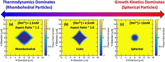
Figure 12. Multi-scale computational model based prediction of particle shape. With increasing Mn2+ concentration, particle shape changes from (a) rhombohedral to (b) cubic to (c) spherical. Adapted with permission from [131]. Copyright (2020) American Chemical Society.
Download figure:
Standard image High-resolution imageMultiple mechanistic model based studies simulating crystallization and precipitation process exist outside the battery literature. PBM has been developed to analyze the effect of different process parameters on size and aspect ratio of crystals in the pharmaceutical industry [150]. It is observed that during a three stage crystallization-milling-dissolution process, process parameters like the rotor speed, number of cycles, amount of mass dissolved affect the particle size and aspect ratio. Heuristic optimization is done using the PBM to produce more equant crystals or to control crystal morphology. Qualitative agreement is obtained between the model and experimental results [151].
CFD-PBM coupled mechanistic models have been developed to predict the effect of process parameters on product crystal properties in pharmaceutical [152], minerals [153], and nuclear industry [154, 155]. Review by Bałdyga elaborates application of CFD-PBM models to 'design' product particles [152]. Coupling the CFD predictions of the hydrodynamic properties (velocity gradients, mixing patterns) with PBM enables prediction of the particle properties and their evolution with time. Such models can predict effect of feed concentration, stirrer speed, impeller type on precipitated particle properties and prove useful in investigating scale-up issues. In the mineral industry, CFD-PBM models have been employed for the precipitation of CaC2O4 and CaCO3 [153]. The influence of stirrer speed, feed point position, feed rate, feed tube diameter, energy dissipation, impeller type on particle properties was investigated. The particle properties include mean particle size, surface area, filterability. This computational strategy makes a priori prediction of change in particle properties due to change in operating conditions possible. The model can be further used for scale-up investigations including how the mean size, size distribution, nucleation rate changes with scale up (specific power input, tank volume). The CFD-PBM models have been used to predict size evolution of uranium oxalate crystals during precipitation reaction in the nuclear industry [154, 155]. Simulation of the flow field allowed accurate description of mixing and effect of hydrodynamics on the precipitate properties. It was concluded that the reagent injection position affects the mean crystal size.
The KLMC simulation technique has been implemented to determine the morphology of the co-precipitated agglomerates of multi-component alloy system [9]. The morphology of Fe-Cu-Mn-Ni-Si alloy was classified in core–shell or appendage category through the simulations. There are two distinctive precipitating phases in this system: the fast precipitating Cu-rich phase acts as heterogeneous site for the slow precipitating phase of MnNiSi. The interplay between interfacial and ordering energies along with active diffusion paths determine the core–shell vs appendage morphology. Thus predicting the morphology of the precipitate (figure 13). Guidelines for designing the co-precipitate microstructure for multi-component system were obtained from the simulations. The specific conclusions derived in this study may not be transferable to multi-component CAM like NMC, NCA. But similar simulation methodology could be developed for desired elements (Ni, Mn, Co). Such model could predict morphology of multi-component CAM particles.
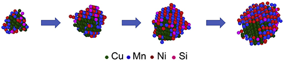
Figure 13. Evolution of Cu-MnNiSi precipitate predicted from kinetic lattice Monte Carlo (KLMC) simulations. Adapted from [9] Copyright (2018), with permission from Elsevier.
Download figure:
Standard image High-resolution imageThe mechanistic models and corresponding development methodologies discussed above are transferable to the co-precipitation synthesis of CAM. Although these models have some limitations, potential further development specific to the procedure under consideration can be achieved. Such models can identify optimum process parameters to produce CAM particles exhibiting desired properties.
4.2. Spray drying (SD) and flame spray pyrolysis (FSP)
SD and FSP has been used extensively in pharmaceutical, food, dairy, minerals industry to generate particles with varying morphology. Variety of particle designs can be generated through the SD and FSP processes by manipulation of process parameters [156, 157]. These processes can be used to generate 'designer particles' exhibiting desired properties. Although SD and FSP have been used for the synthesis of CAM particles [111], respective mechanistic modeling studies are not available in the battery literature.
Mechanistic modeling of the spray drying process involves two steps. The first step is the development of a model to describe drying of a single droplet. This SDD model is then plugged into a CFD model in the second step to simulate the complete spray drying process. Extensive research has been done in the pharmaceutical and dairy industry to develop SDD models predicting drying kinetics of a single droplet [158, 159]. These models can predict particle properties like size, morphology (hollow/dense), and final moisture content. Multiple application examples of such SDD models in the pharmaceutical and dairy industry have been collated [159].
The CFD models simulate the gas flow, heat and mass transfer, evaporation, and solidification of the sprayed droplets. Most of these CFD studies model the continuous gas phase as a Eulerian medium while the droplets are modeled as discrete Lagrangian entities. CFD has been employed to simulate droplet–droplet interactions [160], droplet deposition on dryer wall [161], coalescence and agglomeration behavior [162]. Scale-up of spray drying process is often challenging and CFD can prove useful as a scale-up tool. Different approaches available for design and scale-up of spray drying have been collated [163]. CFD model based methodology can also be used for process development [164]. They prove useful in constructively designing particles with required size, density, and surface properties.
Mechanistic models based on the DEM have been developed for the spray-drying process of silica nanoparticles [165]. DEM was used to understand the effect of internal structures of spray dried granules on the mechanical properties (figure 14(a)). Structural parameters like the macro void, shell thickness, and micro porosity were varied to generate different granule internal structures. Effect of these internal structures on granule mechanical properties are investigated through fracture strength and strain simulations. DEM based mechanistic model have been used to investigated the segregation phenomenon during spray drying of multicomponent aggregates (figure 14(b)) [166].
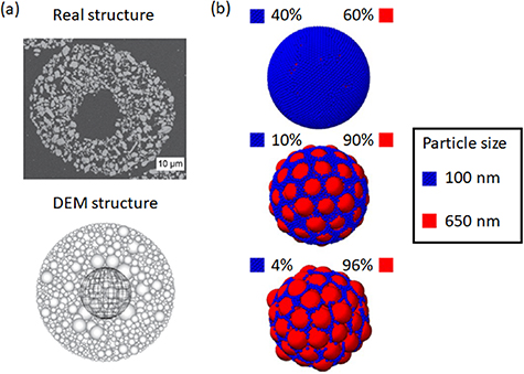
Figure 14. (a) Internal structure of real (top) and DEM generated (bottom) spray-dried particle. Adapted from [165] Copyright (2017), with permission from Elsevier. (b) DEM modeling of segregation due to particle size difference during spray drying of SiO2 particles. Adapted with permission from [166]. Copyright (2015) American Chemical Society.
Download figure:
Standard image High-resolution imageAlong with spray drying, the FSP technique is widely used in the ceramic industry to generate metal oxide nanoparticles such as ZrO2, SiO2, TiO2. Extensive research has gone into developing CFD-PBM coupled mechanistic models to simulating the FSP process. The ZrO2 nanoparticle synthesis was modeled using a Euler–Lagrange framework [167]. The particle dynamics was simulated through a population balance model to obtain evolution of particle volume, area, and number concentration. The simulations can predict the velocity and temperature profiles, droplet evaporation, and particle formation. Figure 15 shows particle and agglomerate diameters predicted through a CFD-PBM model, the predictions are in qualitative agreement with experimental results. The CFD-PBM coupling was used to facilitate tuning of different process parameters to obtain a desired particle size and morphology [168]. Torabmostaedi and Zhang published a series of papers related to mechanistic modeling of the FSP process [169–173]. These simulations enable prediction of particle diameters and variation with respect to multiple process and geometrical parameters. These models require minimal experimental data, hence they are useful for initial process design, reactor optimization, and scale-up.

Figure 15. CFD-PBM simulated spatial evolution of ZrO2 (a) primary (dp) and (b) agglomerate (dg) nanoparticle diameters at various heights above burner (HAB) in flame spray pyrolysis (FSP) for liquid feed (LF) to dispersed gas (DG) ratio: 5/5. (c) Model predictions qualitatively agree with experimental measurements and the model can predict the effect of process parameter (LF/DG) on particle diameter distribution. Primary particle and agglomerate diameters are measured with transmission electron microscopy (dp,TEM, dg,TEM) [168]. Adapted from [168]. CC BY 4.0. © 2019 The Authors. AIChE Journal published by Wiley Periodicals, Inc. on behalf of American Institute of Chemical Engineers.
Download figure:
Standard image High-resolution imageStudies reviewed in this section demonstrate that similar mechanistic models based on CFD, PBM, DEM can be developed for CAM particles synthesized through spray drying and FSP [111]. Such models can prove effective in synthesizing particles with desired properties, in understanding the effect of process parameters on particle properties, as well as in scale-up procedures.
4.3. Grounding or milling
Grounding or milling of materials is performed during the lithiation [40], doping [115, 116], or post-processing [125, 126] step of the CAM synthesis. Although ball-milling is most commonly used during CAM synthesis, variety of mill designs are used across different industries. The review by Brunaugh and Smyth comprehensively show the effect of operating parameters and mill design on the particle properties for pharmaceutical milling process [174]. Process parameters like the solids feed rate, milling duration, revolution rate affect the size distribution, shape, surface area of milled particles. Various analytical and computational mechanistic models have been developed to predict the effect of process parameters on milled particle properties in mining, pharmaceutical, and minerals industry.
Dynamic analytical model has been developed for predicting the power draw and energy usage of the tumbling mills used in minerals processing industry [175]. PBM have been developed for milling of pharmaceutical crystals [150]. PBM can simulate the time and space evolution of the particle size distribution during milling as a function of material and mill characteristics. PBM based models for milling are collated [174]. PBM models are usually developed for specific devices and operating conditions hence have limited applicability.
The DEM based mechanistic model is especially suitable for simulating the milling process. Motion of particles in planetary ball-mill has been simulated [176]. Although the actual breakage of the particles was ignored, the energy transfer from the milling tool to the powder can be predicted. This energy transfer can be plugged into correlations to further determine the milling rate. DEM is an effective tool to analyze the impact of mill geometry (figure 16(a)) [177], mill speed (figure 16(b)) [178], filling ratio of milling balls, milling ball properties, and milling time. It can be used to understand the effect of scale-up on the process dynamics. Similar applications of DEM can be found in case of the semi autogenous mill [179] and tumbling mills [180]. DEM has been used to perform a DoE study to understand the complex effect of multiple operating parameters on the ball-milling of iron ore particles and to further improve the mill design [178].

Figure 16. Application of DEM in simulating effect of (a) mill geometry [177] Reproduced from [177]. CC BY 4.0. and (b) mill speed [178] on particle motion. Colors indicate particle velocities (blue: low velocity, red: high velocity). Reproduced from [178]. CC BY 4.0.
Download figure:
Standard image High-resolution imageDEM is suitable for modeling particle interaction, but wet milling demands more complex models. Interaction between the slurry, grinding media, and mill structure needs to be simulated. For wet milling, DEM needs to be coupled with CFD to simulate the liquid phase [177, 181]. Such complex coupled models can be used to understand how various properties and operational parameters affect the properties of milled particles during wet milling.
As grounding or milling plays an important role during the lithiation and doping step of CAM synthesis techniques, similar predictive mechanistic models can be potentially developed to predict process-product relationship and further optimize the milling parameters to consistently obtain desired particle properties.
4.4. Calcination and sintering
Calcination and sintering is an integral part of all synthesis techniques. Calcination is signified by removal of CO2 or H2O from the precursors to form oxides. Whereas, sintering occurs after the lithiation and doping step. Sintering involves grain growth and densification of the secondary particles. It has been shown that calcination conditions (temperature, ramp rate, holding time) affect the structural and electrochemical properties of cathode materials [182, 183]. The optimum calcination temperature depends on the specific composition and reduces with increasing nickel content [182].
Although mechanistic models for simulating calcination and sintering of TM precursors are unavailable, phase-field method based model has been developed to model sintering of LLZO solid electrolyte used in solid-state batteries [183]. Interface between phases (pores and grains) is tracked as the diffusion of species occurs during sintering. Model demonstrates effect of sintering temperature on particle structure as shown in figure 17.
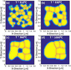
Figure 17. Evolution of particle microstructure during calcination process of LLZO (Lithium lanthanum zirconium oxide) simulated based on the phase field method. With increasing calcination temperature (a) to (d), fraction of pores reduces resulting in dense microstructure. Adapted with permission from [183]. Copyright (2021) American Chemical Society.
Download figure:
Standard image High-resolution imageOutside the battery literature, mechanistic models have been developed for calcination and sintering processes majorly in cement and ceramics industry. Studies focusing on single particle calcination take into account different reactions occurring at different temperatures [184]. Source terms due to these reactions are then incorporated into the conservation equations (mass, momentum, energy, species). Resulting solutions provide profiles of gas velocity, pressure, temperature, and composition throughout the particle.
Calcination of limestone is often performed in the cement industry in large scale calciners or kilns or furnaces. Number of CFD based modeling studies are available for such calciners [185–188]. Euler–Lagrange coupled simulations are developed to simultaneously track the gas and the solid phase. Governing equations involve the conservation equations (mass, momentum, species, energy) along with reaction rate equations. The model can predict temperature and species distribution throughout the calciner during the process.
Extensive research has been gone into developing mechanistic models for sintering of particles. Initial stage sintering models focus on predicting surface area reduction rate [189, 190]. Sintering process is divided into elemental reactions such as absorption of water, diffusion to the neck region, vacancy creation, desorption of water. Reaction rates are derived analytically for each of the elemental steps. Comparison of respective rates to the experimental rate of surface reduction indicates the rate limiting elemental step of the sintering process. Such models are useful in understanding the influence of sintering temperature and atmosphere on the rate of surface area reduction. Rate of neck growth can be incorporated in population balances to investigate particle size evolution during the sintering process [191].
Atomistic model based on DFT and MD is developed to simulate sintering between two neighboring tungsten particles (figure 18) [130]. DFT is useful in predicting the lattice constants, while MD simulations predict movement of atoms during the sintering process.

Figure 18. Density functional theory (DFT) and molecular dynamics (MD) based atomistic model simulating sintering of two neighboring tungsten nano-particles. Neck region increases with sintering time as the temperature increases from (a) to (d). Adapted from [130] Copyright (2010), with permission from Elsevier.
Download figure:
Standard image High-resolution imageDEM finds applications in procedures where stresses are applied to compact the powder and induce sintering [192]. MC method has been implemented to simulate evolution of pore and grain phases during the sintering process [193]. Sintering simulations at the atomistic, microscopic, and macroscopic scales have been collated [194].
Similar mechanistic models based on the DFT-MD, phase field method, MC, DEM can be implemented for calcination and sintering step of CAM synthesis technique. Such models can provide better understanding into the effect of temperature, ramp rate, holding time on final CAM particle morphology.
4.5. Particle coating
ALD technique is advantageous for uniform deposition of conformal coating with controllable thickness on CAM particles [195]. Mechanistic models based on analytical correlations [196, 197], DFT [198–200], MD [201], MC [197, 202], CFD [203] have been applied to investigate the ALD process. Whereas, DEM has been employed to model mechanofusion based dry particle coating [204–206].
Gordon et al developed analytical correlation for achieving uniform coating in a narrow cylindrical hole [196]. The exposure time required to complete the coating increases with increasing aspect ratio of the cylindrical hole. This model was further modified for coating on agglomerates of nanoparticles [197]. Fluidized bed reactor based ALD coating of Al2O3 on SiO2 nanoparticles has been modeled though CFD and analytical correlations [203]. This mechanistic model predicted the bed pressure drop, temperature distribution, and the saturated growth time. Resulting precursor utilization as a function of fluidizing velocity could be used to optimize the coating process. Stochastic MC method has proved useful in predicting coating coverage on 3D structures [202] and agglomerated nanoparticles [197]. Coating of Al2O3 on SiO2 nanoparticles was investigated. As shown in figure 19(a), this approach can predict coating coverage inside nanoparticle agglomerates. With increasing number of particles in the agglomerate, the saturation time increased while the coating coverage decreased (figure 19(b)).

Figure 19. (a) Monte Carlo simulations showing distribution of ALD coating coverage ( ) inside particle agglomerate, (b) Time required for complete coating coverage increases with increasing number of particles (N) contained in the agglomerate. t0 is time required for complete coating coverage of a single particle. Adapted from [197], with the permission of AIP Publishing.
Download figure:
Standard image High-resolution imageMechanistic modeling studies focused on ALD coating have been collated [195, 207]. Similar mechanistic models can be developed for predicting coating quality of CAM particles during the post-processing step.
5. Conclusions from the mechanistic modeling
The synthesis process, mechanistic models, example application, respective industry, and specific insights about the process-product relationship are outlined in table 2. The process-product relationship is qualitatively listed by showing effect of increasing (↑) or decreasing (↓) process parameter on product property. These application examples are obtained from an array of different industries. It is evident that very few studies related to mechanistic modeling exist in the battery literature.
Table 2. Summary of synthesis process, mechanistic model, example application, industry, and process-product relationship. Arrows indicate increasing (↑) or decreasing (↓) parameters.
| Process | Mechanistic model | Example application | Industry | Process-product relationship |
|---|---|---|---|---|
| Crystallization And precipitation | Continuum growth and Monte Carlo | Co-precipitation of NMC111 [149] | Battery | ↑ Solution pH ⇒ ↓ Particle size ↓ Ammonia concentration ⇒ ↓ Particle size |
| DFT and Phase Field Model | Co-precipitation of MnCO3 particles [131] | Battery | ↓ Metal concentration ⇒ Rhombohedral particles ↑ Metal concentration ⇒ Cubic particles ↑ Metal concentration ⇒ ↓ Particle size | |
| PBM | Crystallization-milling-dissolution of needle-shaped crystals [150] | Pharma | ↑ Number of cycles ⇒ ↓ Aspect ratio, ↓ broadness of distribution ↑ Mass dissolved ⇒ ↓ Aspect ratio, ↑ broadness of distribution | |
| CFD-PBM | Supersaturation zone induced precipitation of pharmaceutical crystals [152] | Pharma | ↑ Reynolds number ⇒ First ↓ then slightly ↑ Particle size ↑ Initial concentration in single feed mode ⇒ ↓ Precipitated particle size ↑ Stirrer speed ⇒ ↑ Mean crystal size, ↑ Primary particle diameter, ↑ Agglomerate diameter ↑ Pressure in high pressure nozzle ⇒ ↑ Deagglomeration, ↓ Particle size | |
| Precipitation of CaC2O4 and CaCO3 [153] | Minerals | ↑ Stirrer speed ⇒ First ↑ then ↓ mean particle size, First ↑ then ↓ nucleation rate ↑ Specific power input ⇒ First ↑ then ↓ volume mean crystal size, ↓ Coefficient of variation, First ↑ then ↓ nucleation rate. ↑ Feed point height from impeller ⇒ ↓ Mean particle size at given specific power input. | ||
| Precipitation of uranium oxalate in unbaffled magnetic stirrer [155] | Nuclear | ↑ Reagent feeding distance from axis ⇒ ↑ Mean crystal size, ↓ maximal supersaturation. | ||
| Monte Carlo | Co-precipitation of FeCuMnNiSi alloy [9] | Alloys | ↑ Interfacial energy between matrix and fast precipitating phase ⇒ ↑ Probability of core–shell particle morphology compared to appendage morphology. | |
| Spray drying | Analytical model for single droplet drying | Spray drying of pharmaceutical and dairy powders [159, 208–212]. | Pharma, Dairy | ↑ Time ⇒ ↓ Moisture content, First ↑ then ↓ solute mass fraction, ↑ Solid shell thickness ↑ Droplet radius ⇒ ↑ Solute mass fraction ↑ Difference in component solubility ⇒ ↑ Segregation |
| CFD | 1-D numerical model for spray drying of skim milk concentrates [213] | Dairy | ↑ Dryer height ⇒ ↓ powder moisture, ↓ droplet velocity, ↑ insolubility index, ↑ product temperature. | |
| Simulating spray dryers in pharmaceutical industry [159, 214, 215] | Pharma | ↑ Peclet number ⇒ ↑ Particle porosity ↑ Initial droplet diameter ⇒ ↑ Product particle diameter ↑ Droplet residence time ⇒ First ↓ then constant particle moisture content ↑ Atomization gas flow rate ⇒ ↓ Particle size ↑ Liquid federate ⇒ ↑ Particle size ↑ Solids concentration ⇒ ↑ Particle size | ||
| DEM | Internal structure of spray-dried granules [165] | Ceramic | ↑ Void ⇒ ↓ Fracture strength ↑ Shell thickness + ↑ PP packing density in shell ⇒ ↑ Fracture strength + ↓ Fracture strain ↓ Binder amount ⇒ ↓ Fracture strength & strain | |
| Segregation due to PP size difference [166] | Nano-particles | ↑ Polydispersity ⇒ ↑ Segregation | ||
| Flame spray pyrolysis | CFD-PBM | Synthesis of ZrO2 nanoparticles [167] | Ceramic | ↑ Height above burner ⇒ ↑ Primary particle diameter, ↑ Agglomerate diameter ↑ Dispersion oxygen flow ⇒ ↓ Primary particle diameter, ↑ Agglomerate diameter ↑ Precursor concentration ⇒ ↑ Product particle diameter |
| Synthesis of ZrO2 nanoparticles [168] | Ceramic | ↑ Height above burner ⇒ First ↑ then ↓ nucleation rate, First ↑ primary particle size then remains constant, ↑ Agglomerate size ↑ LF/DG ratio ⇒ ↑ Agglomerate size, ↑ Primary particle size | ||
| Synthesis of ZrO2, TiO2, SiO2 nanoparticles [169–173] | Ceramic | ↑ Pressure drop, ↑ Oxidant/mixture volume feed ratio ⇒ ↓ Sintering of nano-particles, ↑ Number of primary particles per agglomerate ↑ Height above burner ⇒ First ↑ primary particle size then remains constant, ↑ Agglomerate size, ↑ Number of primary particles per agglomerate ↑ Gas to liquid feed ratio ⇒ ↓ Particle mass fraction at given height above burner, ↓ Primary particle diameter, ↑ Agglomerate diameter, ↑ Number of primary particles per agglomerate ↑ Precursor concentration ⇒ ↑ Primary particle diameter | ||
| Effect of nozzle geometry on nanoparticle synthesis [172] | Ceramic | ↑ Oxidant gap size ⇒ ↓ Particle mass fraction at given height above burner, ↓ Sintering rate, ↓ Primary particle diameter, ↑ Number of primary particles per agglomerate, ↑ Agglomerate diameter ↓ Oxygen content in dispersion gas ⇒ ↓ Particle size | ||
| Milling | Analytical model | Tumbling mills for minerals [175] | Minerals | ↑ Feed rate ⇒ ↑ Product yield ↑ Change in feed rate ⇒ ↑ Dynamic response time |
| PBM | Milling of pharmaceutical crystals [150] | Pharma | ↑ Rotor speed ⇒ ↓ Aspect ratio, ↓ broadness of distribution | |
| DEM | Planetary ball mill [176] | Powder | ↑ Revolution speed, ↑ Number of milling balls, ↑ Milling time ⇒ ↑ Product yield ↑ Milling ball diameter and density ⇒ ↑ Particle refinement | |
| Semi-autogenous (SAG) mill [179] | Mining | ↑ Mill speed, ↑ Fill level ratio ⇒ ↑ then ↓ Fraction of fines, ↑ Mill power ↑ Steel ball ratio ⇒ ↑ Fraction of fines, ↑ Mill power | ||
| Ball-milling of iron ore particles [178]. | Mining | ↑ Mill speed ⇒ ↓ Impact toe, ↑ head ↑ Lifter height ⇒ ↓ Impact toe, ↑ head | ||
| CFD-DEM | Wet milling in minerals processing industry [181] | Minerals | ↑ Fill rate ⇒ ↑ Power draw ↑ Disc tip speed ⇒ ↑ Power draw, ↑ Abrasion and wear | |
| Calcination and Sintering | Phase field method | Calcination and sintering of LLZO solid electrolyte [183] | Solid-state battery | ↑ Calcination temperature ⇒ ↑ Grain size, ↓ Pore size ↑ Sintering temperature ⇒ ↑ Relative density |
| Analytical | Calcination of single clay particle [184] | Cement | ↑ Calcination time ⇒ ↑ Conversion, ↑ Particle temperature ↑ Porosity ⇒ ↑ Optimum calcination time | |
| Rate of surface area reduction during sintering [189, 190] | Ceramic | ↑ Water vapor pressure ⇒ ↑ Rate of surface area reduction | ||
| CFD | Modeling calcination in pipe reactor [185], multiple hearth furnace [186], riser chamber [187], cement calciner [188] | Cement | ↑ Temperature ⇒ ↑ Calcination rate ↑ Calciner height ⇒ ↑ Conversion extent, ↑ CO2 Concentration | |
| DFT-Molecular Dynamics | Sintering of tungsten particles [130] | Nano-particles | ↑ Sintering time ⇒ ↑ Neck size, ↑ Densification ↑ Sintering temperature ⇒ ↑ Neck size, ↑ Neck angle, ↑ Densification ↑ Sintering pressure ⇒ ↑ Neck size, ↑ Densification ↑ Misalignment ⇒ ↓ Neck size, ↓ Densification | |
| DEM | Simulating sintering of NiAl powder [192] | Ceramic | ↑ Sintering time ⇒ ↑ Relative density | |
| Monte Carlo | Sintering of Nickel powders [193] | Fuel Cell | ↑ Sintering time ⇒ ↑ Relative density ↑ Relative density ⇒ ↑ Grain size, ↓ Surface to volume ratio, ↓ Pore volume fraction | |
| Particle coating | Analytical | ALD coating on narrow holes [196] and agglomerate pores [197] | Micro-electronics | ↑ Hole aspect ratio ⇒ ↑ Exposure time for complete coating ↑ Number of particles in agglomerate, ↑ Fractal dimension ⇒ ↑ Coating time |
| Monte Carlo | Fluidized bed atomic layer deposition (ALD) coating on agglomerates of nano-particles [197] | Nano-particles | ↑ Gas pressure ⇒ ↓ Coverage ⇒ ↑ Coating time ↑ Number of particles in agglomerate, ↑ Fractal dimension ⇒ ↓ Coverage ⇒ ↑ Coating time | |
| CFD | Fluidized bed reactor based ALD particle coating [203] | Nano-particles | ↑ Precursor mass fraction ⇒ ↓ Minimum pulse time, ↓ Precursor waste ↑ Fluidizing velocity ⇒ First ↑ then ↓ precursor utilization | |
| DEM | Mechanofusion based dry coating [204–206] | Nano-particles | ↑ Particle loading, ↑ RPM ⇒ ↑ Compressive force |
Similar mechanistic models can be implemented in the CAM synthesis technique to better understand the process-particle structure relationship. As shown in figure 20, in the co-precipitation or template synthesis technique, CFD can be implemented to understand the fluid flow in the reactor, then the CFD model can be coupled to PBM to predict particle size evolution of precursor particles. If the spray drying or flame spray pyrolysis is chosen for precursor precipitation, mechanistic models related to the drying of single droplet can be developed. CFD along with energy balance can be implemented for prediction of evolution of precursor particle properties. For grounding or milling during lithiation and doping step, DEM can be used to predict effect of process parameters on particle properties. Phase field method based models can be developed for further understanding of the calcination and sintering process. Mechanistic models based on MC, CFD, DEM could be developed for the particle coating process. Once the process parameters are correlated to the product particle properties, these processes can be further optimized.

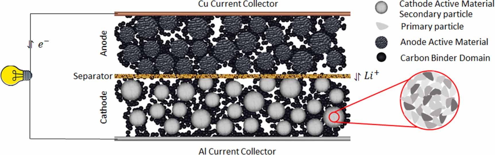
Figure 20. Suitable mechanistic models and corresponding investigative aspects for various processes involved in the cathode active material synthesis techniques.
Download figure:
Standard image High-resolution image
To build confidence in the accuracy of different mechanistic models, experimental validation is important. Required data for such validation can be obtained from variety of process monitoring techniques. The continuous manufacturing platforms of pharmaceutical industries employ a variety of process monitoring techniques to characterize the product at different stages of the process. Apart from validation, this data can be used for drawing valuable insights related to the process-product relationship. For further detailed information on different process monitoring tools, readers are referred elsewhere [28, 29].
It is evident that the predictive mechanistic models and process monitoring tools can be implemented during the CAM synthesis techniques to produce particles with desired morphology. The mechanistic understanding is even more important in the battery industry, as the final particle morphology directly affects the electrochemical performance of the cell. With the ability to predict particle morphology based on a synthesis technique will come the opportunity to design new particle morphologies favorable for enhanced electrochemical performance.
6. Conclusions and outlook
Range of synthesis techniques have been employed by researchers to generate a variety of CAM particle morphologies in the hope of enhanced electrochemical performance. Distinct particle structures can be generated by modifying the synthesis procedures. Final particle morphology was not pre-determined in many of the CAM synthesis studies reviewed in this work. The particle morphology resulted due to the specific combination of different process parameters involved in the synthesis technique. The ability of a-priori determination of the particle structure based on a given synthesis technique is lacking in the battery literature.
Different mechanistic models are used in other industries that enable the prediction of particle properties based on the process parameters. These models are useful in predicting the product properties without vigorous experimentation. Multiple mechanistic models are often need to be coupled together for accurate description of the complete process. These mechanistic models have proved beneficial in deeper understanding of the process-product relationship and better control over the product properties.
Variety of mechanistic models can be applied to different processes involved in various CAM synthesis techniques to investigate the process-particle structure relationship. There are very few studies in the battery literature that focus on mechanistic model development. The effectiveness of models discussed in this review should be explored further. Implementation of such mechanistic models will result in increased understanding of the process-product relationship, reduced experimental trial and error, consistent product properties, and effective scale-up.
Similar to CAMs, mechanistic modeling can be applied to processes involved in the synthesis of anode active material. Works reviewing different synthesis techniques available for anode active materials along with electrochemical performance data exist in the literature [10, 36, 216–222]. Mechanistic modeling methods depicted in figure 20 can be similarly implemented for anode active material synthesis to investigate the effect of the process parameters on particle properties.
Apart from the synthesis procedure, possibilities of mechanistic model development exist in the downstream steps of the electrode manufacturing train such as, slurry mixing, slurry casting, electrode drying, calendaring, assembly of the cells and modules. Knowledge about the model development can be transferred from industries where similar processing is done. For example, the slurry casting process can draw from the extensive developments made in the paper and paint coating industry for optimization of the coating process.
Increased process control is becoming a necessity given the exponential rise in the demand for Li-ion batteries. It is imperative that opportunities for mechanistic model development should be identified throughout the cell manufacturing train and predictive models should be implemented to better understand the process-product relationship.
Acknowledgments
Authors acknowledge the funding provided by the faraday institution FIRG015.
Data availability statement
No new data were created or analysed in this study.
Conflict of interest
The authors have no conflicts of interest to declare.