

Abstract
In this work, the performance of copper(II) hexacyanoferrate(III) (CuHCF) as a cathode material for lithium-ion batteries was studied. The compound was synthesized by a precipitation reaction in aqueous solution in a closed system. The morphology and structure show nanoparticles with sizes between 40 and 70 nm with a high agglomeration and a crystalline phase with a cubic structure, respectively. The material exhibited a stable performance with a working potential of around 3.6 V vs Li+/Li and a decrease in the charge transfer resistance due to increased ionic conductivity. The gravimetric capacity obtained is near 60 mAh g−1 during 300 cycles at a rate of C/20, close to the practical capacity. Considering its electrochemical performance, CuHCF could be a promising cathode material for lithium-ion batteries.
Export citation and abstract BibTeX RIS
Today, society faces a huge challenge to meet the growing demand for high-efficiency, large-scale production, and store energy. Vehicles are a significant consumer of fossil fuels, and the introduction of hybrid electric ones are an alternative. 1,2 Additionally, energy storage is a critical component in the service industry, renewable energy industry, and all electronic devices where it places increasing demands on energy storage capacity. 3 For many of these applications, lithium batteries are an excellent choice because lithium has a high theoretical specific gravimetric capacity (3850 mAh g−1), and a high reducing power (−3.05 V vs N.H.E.) so it has a high energy density (260 Wh kg−1). However, the metal's high reactivity causes the formation of hydrogen gas in an exothermic reaction when it has contact with humidity in the organic electrolyte. 4 For this reason, graphite is employed as an anode material to avoid these inconveniences in the well-known lithium-ion batteries (LiBs). The cathodes in LiBs, are a crystalline network with cavities that allow an electrochemical ion insertion. 5 A group of materials that have been studied in this area is the family of metal polycyanometalates (MPCMs) mainly due to their low cost, high durability, electronic conductivity, easy obtention, and show promising electrochemical performance. 6–9 Within this family, metal hexacyanometalates (MHCMs), where Prussian blue (PB) is well-known, have a high chemical and electrochemical reversibility, 10 allowing their application in magnetism, photomagnetism, ion capture, gas adsorption and as electrode material. 9,11–16 Since 1978, 17 the application of PB and PB analogs in electrochemical insertion studies, e.g., PB and nickel(II) hexacyanoferrate(III) as cathodic materials in LiBs 6,18 have been reported. Copper(II) hexacyanoferrate(III) (CuHCF) is well-known in the treatment of nuclear waste, thanks to its ability to selectively separate radionuclides from Cesium. 19 Additionally, CuHCF compounds have received attention as potential candidates for CO2 capture. 20 The remarkable electrochemical properties of this compound as a nanoparticle, allowed its use as an insertion electrode in aqueous rechargeable Zinc-Ammonium hybrid batteries. 21 These electrodes show extremely high rate performance and excellent cycling performance when were employed in potassium secondary batteries 22 reaching about 2/3 of the theoretical capacity and 80% of the retention capacity after 40000 cycles at 0.83 C. In this work, CuHCF nanoparticles were obtained and employed as cathode material in LiBs. It was possible to adequately study in a half-cell configuration, obtaining capacities close to 60 mAh g−1, which is identical to the theoretical capacity of the material with zeolitic H2O and coordinated to the structure, high cyclic stability and efficiencies close to 95% during 300 cycles.
Materials and Methods
Synthesis of the material: Copper (II) hexacyanoferrate (III) (CuHCF) was synthesized using K3Fe(CN)6 (Merck) 0.125 M, CuCl2 2H2O (Merck) 0.25 M as precursors and KCl (Merck) 1 M as potassium counter-ion. For synthesis, 20 ml of each solution was mixed in a 100 ml beaker with constant stirring for 10 min The synthesis was carried out in a closed system at a constant temperature of 30 °C for 2 h. At the end of the reaction time, a colloidal solution was obtained, which was centrifuged at 4500 rpm to separate the solid from the supernatant. The solid (CuHCF) was washed three times with deionized water and allowed to dry in an oven at 60 °C for 12 h, obtaining a brown powder.
Material characterization: The powder obtained was characterized by X-ray diffraction (XRD, Bruker model D8 Advance with Cu tube (40 mA, 40 kV)), field emission scanning electron microscopy (FESEM, QUANTA FEG250), transmission microscopy electronics (TEM, JEOL JEM 1400) and thermogravimetric analysis (TGA/DSC 1 Star System, Metler Toledo).
Electrode fabrication, electrochemical measurements and post mortem analysis: To prepare the electrode material, first the CuHCF was washed with deionized water and dried under vacuum at 100 °C for 12 h to remove the remaining KCl from the synthesis. Then, CuHCF was mixed with super P carbon (Timcal) and polyvinylidene difluoride (PVDF, Aldrich) in proportions of 80:10:10, respectively, in N-Methyl-2-Pyrrolidone (NMP, ITW reagents) as dispersing agent for 30 min at 4000 rpm using an Ultra-Turrax disperser (IKA digital model T18). The resulting suspension was deposited on a carbon current-collector (GDL ELAT1400, Fuel Cells Store) using the Dr Blade technique. Finally, the composite deposited on the carbon substrate was dried at 50 °C for 12 h in an oven to evaporate the solvent completely. The electrodes were cut with a diameter of 13 mm (deposited mass 7 mg cm−2) and vacuum-dried at a temperature of 100 °C for 3 h using a glass vacuum oven (Buchi). After drying, the electrodes were transferred to a MBraun 150 glove chamber with controlled argon atmosphere for mounting coin-type batteries (CR2032). The configuration used was a half-cell where the negative electrode was a metal lithium chip with a diameter of 13 mm, a Whatman filter of 16 mm diameter fiberglass was used as a separator, and 1 M LiPF6 electrolyte (Aldrich) in a mixture of ethylene carbonate: diethyl carbonate (EC: DEC 50:50 by volume) was used. Finally, the battery was hermetically sealed using a hydraulic press, applying a pressure of 800 psi. Cyclic voltammetry (CV) measurements were performed using a potenciostat/galvanostat (Autolab, PGSTAT204) in the potential range of 2.5–4.3 V vs Li+/Li. Galvanostatic charge/discharge cycling tests of the cells were performed in a voltage of 2.5–4.3 V vs Li+/Li in a battery tester Arbin BT2143. The program employed started in discharge mode from open-circuit voltage (3.2 V vs Li+/Li) until 2.5 V, and later was charged until 4.3 V. Electrochemical impedance spectroscopy (EIS, PGSTAT204) measurements were carried out with a frequency ranging from 100 kHz to 10 mHz at an amplitude of 10 mV. The configuration used was a coin-type battery (2032) where the negative electrode was a metal lithium chip with a diameter of 13 mm. The electrolyte and separator were the same used in the CV and galvanostatic charge/discharge measurements.
Post mortem analysis of the cycled electrode was performed by manually disassembling cell 2032, separating the CuHCF cathode from the rest of the components. This cathode material was dried at room temperature and analyzed by X-ray diffraction.
Results and Discussion
XRD characterization
The crystal structure and phase of the material was determined by powder X-ray diffraction shown in Fig. 1a. The synthesized CuHCF powders show a high crystallinity and the diffraction peaks can be indexed in the face centered cubic structure of Cu(Fe(CN)6)0.667 (86–0513; Fm3m, a = b = c = 10.1 Å). This crystal structure agrees with the results obtained in the EDX analysis where the stoichiometric relationship between Fe and Cu is 0.62 (Fig. S1 (available online at stacks.iop.org/JES/168/080515/mmedia)). The reaction that summarizes the formation of CuHCF can be represented as:
Crystallite size was estimated by Rietveld analysis using the XRD peak indexing software FULLPROF, as shown in Fig. 1b. This information was used to identify the unit cell lattice symmetry cubic belonging the  space group (CIF Code 1010359), with the unit cell parameters determined to be as follows: a = b = c = 10.121(4) Å, α = β = γ = 90° and crystal size 67 nm. The R parameters were Rp = 20.0, Rwp = 29.4, Rexp = 35.5 and χ2 = 1.54. The CuHCF, whose structure was proposed by Keggin and Miles,
23
it consists of a simple cubic with chains of –Fe−C−N−Cu−N−C−Fe− along the three crystallographic directions forming an octahedron. Each unit cell consists of eight cells and therefore contains eight insert sites that allow both monovalent and polyvalent ions to be accommodated. Cell size is an important parameter to facilitate insertion of lithium-ion (59 pm), in this case (10.121 Å = 1012 pm), therefore it is possible to house these ions.
space group (CIF Code 1010359), with the unit cell parameters determined to be as follows: a = b = c = 10.121(4) Å, α = β = γ = 90° and crystal size 67 nm. The R parameters were Rp = 20.0, Rwp = 29.4, Rexp = 35.5 and χ2 = 1.54. The CuHCF, whose structure was proposed by Keggin and Miles,
23
it consists of a simple cubic with chains of –Fe−C−N−Cu−N−C−Fe− along the three crystallographic directions forming an octahedron. Each unit cell consists of eight cells and therefore contains eight insert sites that allow both monovalent and polyvalent ions to be accommodated. Cell size is an important parameter to facilitate insertion of lithium-ion (59 pm), in this case (10.121 Å = 1012 pm), therefore it is possible to house these ions.
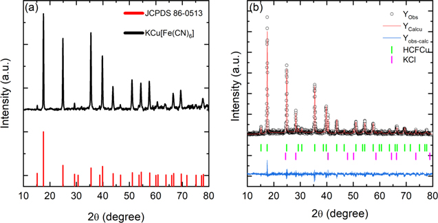
Figure 1. (a) XRD patterns of KCu[Fe(CN)6] nanoparticles obtained and (b) Rietveld refined powder XRD pattern of the as-synthesized KCu[Fe(CN)6].
Download figure:
Standard image High-resolution imageCharacterization by FESEM and TEM
The co-precipitation of CuHCF in the presence of excess Cu2+ proceeds more slowly, allowing for ordered growth of highly crystalline, polydisperse nanoparticles. On the other hand, the CuHCF nanoparticles obtained under these conditions readily precipitate into larger agglomerations, which can be easily filtered and processed for use in battery electrodes. 24 Field emission scanning electron microscopy (FESEM) was used to study the morphology of the CuHCF. The FESEM images shown in Fig. 2a, indicate a particle size ranged between 40 and 70 nm corresponding to usual morphologies of these agglomerates, and consistent with those determined by XRD. Using transmission electron microscopy (TEM, Fig. 2b), it can be seen that the particles are agglomerated and with a cubic morphology that cannot be appreciated by FESEM.
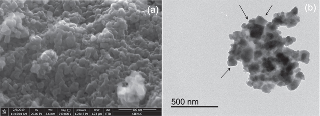
Figure 2. (a) FESEM and (b) TEM images of prepared CuHCF nanoparticles.
Download figure:
Standard image High-resolution imageCharacterization by thermogravimetric analysis, TGA
Analogs of PB compounds generally have water absorbed in their structure, which can be found in two forms: a) as zeolitic H2O in the cavities formed by the M'−CN−M network, and b) as coordinated H2O replacing vacancies of the octahedron cavities formed by Fe(CN)6 3−. 25,26 According to the XRD and EDX analysis, the synthesized CuHCF has a vacancy fraction of 0.62. The TGA in Fig. 3 shows that weight loss occurs in two steps.
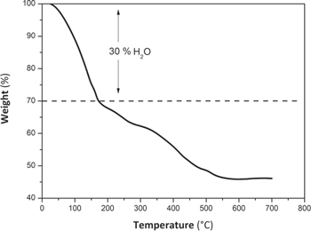
Figure 3. TGA curve for synthesized CuHCF. N2 flow 100 ml min−1 with a temperature ramp from 25 °C−700 °C.
Download figure:
Standard image High-resolution imageAccording to Fig. 3, heating from room temperature to about 180 °C, produces 30% of mass loss corresponding to: i) adsorbed humidity, zeolitic water and coordinated water in the structure, i.e., equivalent to 6 molecules per unit of formula. Above 180 °C, a gradual decomposition of the CN group into (CN)2 occurs, obtaining Cu and Fe as final products. 27 Therefore, the molecular formula of the synthesized compound can be considered to have now six more water molecules, KCu[Fe(CN)6]0.667·6H2O.
Electrochemical performance of CuHCF as a cathode for LiBs
The electrochemical performance of the cathode was evaluated using CV and galvanostatic curves (GC) at room temperature, under the experimental conditions described in the experimental section. Figure 4 shows the voltammetric profile of a lithium half-cell with a cathode based on CuHCF, at a scan rate of 0.1 mV s−1 and at a potential ranged of 2.5−4.3 V vs Li+/Li. The CV shows a quasi-reversible insertion step (3.6 V) and extraction (3.8 V) of lithium ions, resulting from a separation of peak potentials about 200 mV and a relationship between the oxidation/reduction areas close to 1 These redox reactions correspond to the iron (Fe2+/Fe3+) carbon-coordinated in the CuHCF structure. This type of compound has only one active center because copper nitrogen-coordinated has such a low solubility product that a reduction of this metal ion shifts to an inaccessible value. 16 However, a little shoulder observed at 2.6 V vs Li+/Li could be attributed to the reduction of copper ions into CuHCF structure. Similar results have been observed by O. Makowski et al. 9 in the electrochemical insertion of K+ ions into a CuHCF film deposited on a glassy carbon electrode.
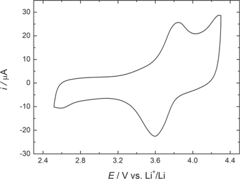
Figure 4. CV of a lithium half-cell with a cathode based on CuHCF. Scan rate 0.1 mV s−1 and potential range of 2.5–4.3 V vs Li+/Li.
Download figure:
Standard image High-resolution imageThe lithium-ion insertion process during iron reduction can be represented by Eq. 2:
The GC allow obtaining the reversible specific capacity (C) of both discharge and charge processes. However, despite having the results of both, the subsequent analysis and discussions are made based only in the discharge process. The variation of "C" will allow correlating electrochemistry with structure and morphology. This correlation is possible through the C-rate analysis, reversibility, cyclability, coulombic efficiency, retention, and remaining capacity percentage.
In order to obtain the optimal C-rate condition, the CuHCF material was subjected to ten cycles at different C-rates. Figure 5 shows an increase in storage capacity from 40 mAh g−1 to 60 mAh g−1 when decreasing charging rates from 1 C to C/20, respectively. The average specific capacity and retention capacity for CuHCF obtained in this study are summarized in Table SI. Also, a high discharge/charge reversibility could be observed in all the cases. Comparing the average specific discharge capacities in the initial 1 C state (39 mAh g−1) with the final 1C state (42 mAh g−1), the material is observed to have high mechanical stability.
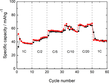
Figure 5. C-Rate study of CuHCF as cathode in a LiB. ( ) charge; (□●□) discharge.
Download figure:
Standard image High-resolution imageThe results summarized in Table SI show an increase in the average specific capacity at longer discharge/charge times, reaching an additional retention of 65.4% at C/20. Therefore, a C/20 value has been chosen to carry out more in-depth cyclability studies. Figure 6 represents the galvanostatic charge/discharge curves as a function of lithium-ion insertion and the variation of the specific capacity and the coulombic efficiency obtained during 300 cycles.
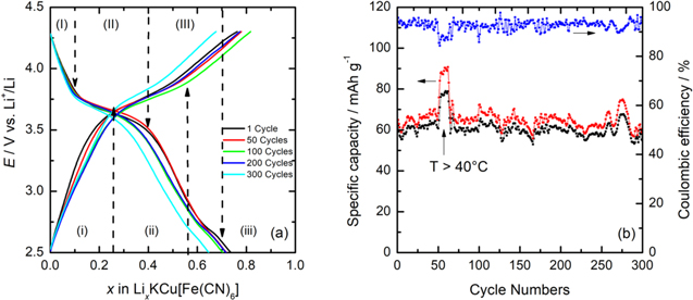
Figure 6. (a) Galvanostatic charge/discharge profile of the CuHCF at C/20 and; (b) the specific capacity and coulombic efficiency as a function of the cycle numbers. ( ) charge; (□●□) discharge.
Download figure:
Standard image High-resolution imageIn Fig. 6a, charge/discharge profiles have been divided into different zones. In discharge mode (down arrows) can be observed three zones: (I), (II), and (III). In zone (I), from the upper cut-off potential (ca. 4.3 V) until ca. 3.8 V, the potential drops abruptly due to a high cell's polarization. These conditions produce an increase in the internal cell's impedance (ohmic resistance) and an increase in the compound's solubility. Subsequently, in the zone (II) located between 3.8 V to 3.5 V, a slight drop potential is produced (pseudo-plateau). This zone's composition range is around 0.1 < x < 0.4, typical of a topotactic transition described by Eq. 2. Here, lithium ions are inserted into the CuHCF structure occupying the octahedron sites. During this insertion, Fe3+ is reduced to Fe2+ at a potential close to 3.5 V. In zone (III), at a global composition range between ca. 0.4 < x < 0.73, another pseudo-plateau is observed due to a topotactic transition, where more than one Li+ ion per formula unit is inserted during the second and third discharge, showing this small pseudo-plateau. 28 Here, the most lithiated phase is further enriched, while a second phase is impoverished, maintaining a constant global composition. At the end of zone (III), a single-phase reaction occurs again with its abrupt potential drop (lower cut-off potential ca. 2.7 V). Finally, in the zone (III) located in the global composition range between ca. 0.6 < x < 0.73, a capacity increase is observed mainly due to the reduction of Cu2+ ions occurring at 2.5 V, which is in agreement with cyclic voltammetry. According to these results, lithium ions' insertion reaches a maximum ca. x = 0.73 during the first discharge cycle and an average ca. x = 0.70, considering the first 150 cycles and a final value x = 0.63 for cycle 300. In charge mode (up arrows) can be observed three zones: (i), (ii), and (iii). In zone (i), a significant potential increase occurs from 2.7 V to 3.3 V, with a remotion of lithium ions around x = 0.25. Subsequently, in zone (ii), a pseudo-plateau between 3.3 V and 3.5 V is observed associated to the oxidation of Fe2+ to Fe3+ at this potential with the remotion of x = 0.55 (cycle 100) and x = 0.47 (cycle 300) of lithium ions. Finally, in the zone (iii), lithium ions' remotion reaches 80% at cycle 100 and 60% at cycle 300, increasing the voltage from 3.5 V to 4.3 V.
In Fig. 6b, the reversible specific capacity and the coulombic efficiency remain relatively constant during 300 cycles, representing the behavior of the cell subjected to in-depth discharge/charge studies. The average specific capacity achieves a close value to the theoretical specific capacity and a coulombic efficiency of 95%. The stability of the coulombic efficiency is due to the high retention capacity at C/20 (see Table SI). A plot of the percentage of remaining capacity as a function of cycle numbers (cf. Fig. S2) indicates a remaining capacity of 90.5% in the tenth cycle. However, when cycling increases, the remaining available capacity returns to an average of 96.8% for practically 250 cycles. High remaining capacity and high coulombic efficiency suggest that the host material has an excellent reversibility for the charge/discharge processes, rate capability, and life cycle. Additionally, it could be demonstrated excellent structural stability because XRD postmortem (Fig. S3) does not show a phase change, so holding the initial cubic structure.
Another interesting feature in Fig. 6b was the increase in the specific capacity of both processes when the temperature exceeded 40 °C (cycle 50th to 60th), going from ca. 60 mAh g−1 to 80 mAh g−1 for discharge and ca. 90 mAh g−1 for charging. This significant change in the capacity is due to this study was carried out during August in the city of Córdoba (Spain), which during summer reaches temperatures close to 45 °C, being one of the hottest regions in the country (holidays time and the air conditioning in the laboratory was disconnected). The temperature has a significant impact on the performance and lifetime of LiBs. At low temperatures, the ionic conductivity of the electrolyte is significantly reduced, hindering ions transport. 29 In this case, an experiment carried out at 40 °C increased the ionic conductivity of the electrolyte, with the subsequent increase in the storage capacity. The theoretical capacity for KCu[Fe(CN)6] is 85.1 mAh g−1 in its anhydrous form. Through the ATG analysis, it was possible to determine six more water molecules. Accordingly, it could be expected a decrease in capacity from 85.1 mAh g−1 to value ca. 60 mAh g−1. In practice, the capacities obtained are generally close to 60 mAh g−1 and, in some cases less, since the structure has both zeolitic and adsorbed moisture. 24 Fe(CN)6 3− vacancies allow water molecules to be incorporated in two ways in the CuHCF structure: i) the zeolitic water molecules have a strong tendency to reside in or to compete with Li+ ions to occupy the interstitial spaces, which may block the transport of Li+ ion into the inside of the lattice, thereby lowering the capacity utilization of PB framework; 30 ii), the water is coordinated to the metal ions located in exposed sites of the CuHCF vacancies. The oxygen atoms in the water molecule help protect the positive charge of the transition metal ions that are exposed. In this case, the relationship between vacancies and water is complementary because each additional vacancy exposes an additional interstitial ionic site for coordination and increases the available volume for zeolitic water. Zeolitic water can be removed more easily than coordinated water heating the material, as it is more loosely bound. Water can also influence the thermodynamically favored phase; solvate lithium, reducing its effective ionic potential and mitigating the cubic to the rhombohedral displacement of the crystal structure. 26 Table I shows a comparison between results obtained for different cathodes based on metal hexacyanometalates and other types of compounds that have been studied.
Table I. Comparative results of compounds belonging to the hexacyanometalate family and other types of compounds, obtained from references.
| Compound | References | Working potential/V | Nanoparticle size/(nm) | Synthesis method | C-rate | Capacity/mAh g−1 |
|---|---|---|---|---|---|---|
| CuHCF a) | a) | 3.6 | 40–70 | Co-precipitation | C/20 | 60 |
| NiHCF | 6 | 3.3 | 20–50 | Co-precipitation | C/5 | 52 |
| NiHCF | 7 | 3.3 | 20–50 | Co-precipitation | C/6 | 59 |
| CuHCF | 24 | 3.7 | 20–50 | Co-precipitation | 1.2C | 59.1 |
| MnHCF | 31 | 3.5 | 200–400 | Sol-gel | 83C | 40.1 |
| FeHCF | 18 | 3.1 | 40–60 | co-precipitation | 3C | 138 |
| LiPB-PPy-PPs | 32 | 3.5 | 120–250 nm | co-precipitation | 3C | 119 |
| LiCoO2 | 33 | 3.8 | 50–200 | hydrothermal | C/10 | 150 |
| LiMnO2 | 34 | 3.3 | 30–100 nm | hydrothermal | C/20 | 250 |
| LiFePO4 | 35 | 3.4 | 40–50 | precipitation | C/20 | 160 |
| NMC | 36 | 3.7 | 100–250 | co-precipitation | C/20 | 170 |
The manganese-based compound's behavior stands out from the table since, at a very high C-rate, it is capable of retaining 67% of theoretical capacity. Concerning our compound, it can be noted that capacities similar to those obtained by other authors are achieved. Additionally, it has been found a decrease in a electrochemical performance of CuHCF in LiBs, compared with NaBs and KBs. 37 One possible interpretation of this behavior involves the size of the inserted species, often expressed in terms of the Stokes radius, which is a parameter experimentally determined by experiments in aqueous systems and can be corrected for non-aqueous solutions. 34 The higher the charge to radius ratio of an ion, the more strongly water molecules will coordinate to it, so a smaller effective ionic radius results in a larger Stokes radius in aqueous solutions. Therefore, batteries based on Li+ ions present a worse performance than Na+ and K+ ions when metalhexacyanometallates are used as active materials.
Electrochemical impedance spectroscopy measurements
EIS is a technique that measures resistance (R), capacitance (C), and inductance (L) by monitoring the current response while applying an AC voltage to an electrochemical cell. Impedance is defined as the resistance that interrupts or out of phase current when an AC voltage is applied to the circuit. 35 During the cycles of a LiB, its internal impedance will slowly increase. The higher the impedance of a battery, the more difficult it is to move lithium ions through it. This feature occurs at extreme high or low temperatures, or as a result of the growth of a solid electrolytic interface layer (SEI). 31 Figure 7 shows that changes in battery impedance as charge/discharge cycles increase at a rate of 1C, and Table II shows the parameters obtained from the equivalent circuit.
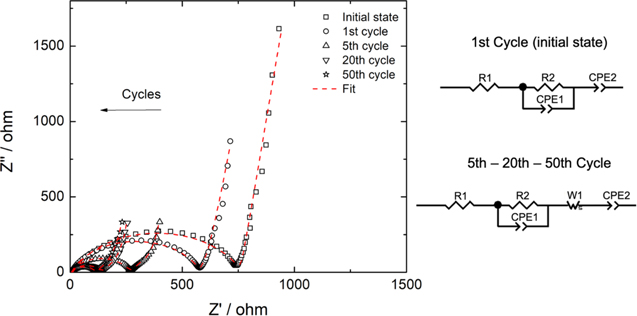
Figure 7. Nyquist plot and equivalent circuits from EIS measurements.
Download figure:
Standard image High-resolution image
Table II. Values of the circuit parameters: electrolyte resistance, charge transfer, and the double layer capacity from EIS measurements.
| State | R1 = RELECTROLYTE (Ω) | R2 = RCHARGE TRANSFER (Ω) | CDOUBLE LAYER/% error (μF) |
|---|---|---|---|
| Initial | 11.6 (± 0.1) | 749 (± 5.2) | 3.16/3 |
| 1st Cycle | 5.78 (± 0.14) | 574 (± 13) | 2.97/7 |
| 5 Cycles | 5.66 (± 0.13 ) | 260 (± 5.7) | 2.63/9 |
| 20 Cycles | 5.59 (± 0.14) | 131 (± 3.2) | 2.20/12 |
| 50 Cycles | 5.68 (± 0.04) | 109 (± 0.52) | 2.17/3 |
EIS consists mainly of three regions, i.e., the low-frequency region, the mid-frequency region, and the high-frequency region. 36 In the low-frequency region, the EIS appears as a straight line with a constant slope associated with a diffusion phenomenon. In this case, for the initial state and first cycle, a constant phase element (CPE2) was adjusted instead of a Warburg impedance because the latter caused a failure in the fit, and a CPE corresponds to a Warburg element of infinite-length. 37 In cycles 5−20−50, the circuit was correctly fit with both elements, showing infinite diffusion in the final process. The mid-frequency region was modeled by a parallel connection of a constant phase element (CPE1) and a resistance (R1) that corresponds to the resistance to charge transfer. The constant phase element was used instead of a capacitor to compensate for the electrode's non-ideal behavior, which corresponds to carbon current-collector (GDL). Finally, R1 corresponds to the electrolyte's resistance that describes the behavior of the battery at high frequencies. The Nyquist plots were analyzed by Zview software and show that an increase in charge/discharge cycles produces a decrease in the charge transfer resistance, from 749 Ω for the initial state to 109 Ω at the end of cycle 50 (smaller semicircles). This decrease in resistance can be attributed to the increase of ionic conductivity with cycles which is related to a positive effect of vacancies in the CuHCF structure. The interconnected cavities offer an alternative route to insertion other than the channels [100], and there is evidence to suggest that the vacancies allow the conduction of larger ions. 26 These changes play a fundamental role in the electrochemical performance and lifecycle of LiBs because it prevents the electrode surface from further reacting with the electrolyte. Furthermore, the double layer's capacity also decreases from 3.16 μF for the initial state to 2.17 μF at the end of the 50 cycles. This is due to a decrease in the insulation layer produced initially when charge/discharge cycles increase as a result of improving conductivity. 38 These results are consistent with those observed for specific capacity in Fig. 6b and demonstrate that the material has a low charge transfer at the beginning. However, as its restructuring begins by incorporating lithium ions, it improves its stability and conductivity.
Conclusions
A simple co-precipitation reaction for the synthesis of copper(II) hexacyanoferrate(III) (CuHCF) produced highly crystalline cubic structure (40–70 nm) agglomerated nanoparticles. Studies carried out using this material in LiBs showed that the material's performance approaches its practical limit during 300 charge/discharge cycles, at low speeds (C/20), with gravimetric capacities close to 60 mAh g−1 and working potential around 3.6 V Li+/Li. This value is less than the theoretical value (85.1 mAh g−1) due to water molecules (zeolitic or coordinated form) in Prussian blue analogs, which reduce the ion charge capacity. This value could improve by using a moisture-free solvent to avoid structural H2O. Despite low values in capacity, the electrochemical impedance showed a decrease in the resistance to charge transfer with each cycle due to the increased of ionic conductivity. Additionally, the insulating layer that forms between the cathode and the electrolyte is diminished with increasing charge/discharge processes. These results indicate excellent electrochemical activity and structure stability, this last confirmed by an XRD postmortem. Although performance should be improved because the material's capacity is low compared to commercial ones, this study provides knowledge of CuHCF as a cathode material in LiBs, which has been little reported in the literature.
Acknowledgments
We acknowledge the financial support from FONDECYT, Chile, (grant no. 1180784), from VRIEA-PUCV (grant no. 039.438 NÚCLEO-PUCV and 125.737/2021 DII-PUCV), from the Spanish Ministerio de Economía y Competitividad (Project MAT2017-87541-R) and from Junta de Andalucía (Group FQM-175) and from FONDEQUIP EQM150101. E. Navarrete thank for the financial support from postdoctoral project FONDECYT (N° 3200216). V. Rojas would like to acknowledge the kind support from his doctoral scholarship by ANID N° 21160733. F. Herrera thanks DICYT-USACH for their financial support.