Since the beginning of the German collaborative research center SFB-TRR 40 in 2008 ArianeGroup has been involved as industrial partner and supported the research activities with its expertise. For the final funding period ArianeGroup actively contributes to the SFB-TRR 40 with the self-financed project K4. Within project K4 virtual thrust chamber demonstrators have been defined that allow the application of the attained knowledge of the entire collaborative research center to state-of-the-art numerical benchmark cases. Furthermore, ArianeGroup uses these testcases to continue the development of its in-house spray combustion and performance analysis tool Rocflam3. Unique within the collaborative research center fully three-dimensional conjugate heat transfer computations have been performed for a full-scale 100 kN upper stage thrust chamber. The strong three-dimensionality of the temperature field in the structure resulting from injection element and cooling channel configuration is displayed.
1 Introduction
After the 2002 launch anomaly during the Ariane 5 flight VA-157, the first flight to utilize the novel Vulcain 2 engine, the inquiry board found the degraded thermal condition of the nozzle due to fissures in the cooling tubes and a non-exhaustive definition of the flight loads on the engine as root causes for the failure
[2].
At the time already some joint French-German research projects on liquid rocket engine combustion modeling and combustion stability such as e.g. the Rocket Engine Stability Initiative (REST) program existed with participation from industry, universities and research institutes. To advance the involvement of the German academic institutions in liquid rocket propulsion activities the Deutsche Forschungsgemeinschaft (DFG) funded collaborative research center Sonderforschungsbereich Transregio 40 (SFB-TRR 40) on Fundamental Technologies for the Development of Future Space-Transport-System Components under High Thermal and Mechanical Loads was founded in 2008.
Advertisement
As the major actor in the European space transportation activities and prime contractor for the Ariane 5 ArianeGroup has been involved in the research activities from the very beginning. Ever since, ArianeGroup has been actively participating in the SFB-TRR 40 providing its expertise in both system aspects as well as detailed component design.
Based on the basic research activities that commenced in 2008 one major objective of the final funding period of the SFB-TRR 40 lasting from 2016 to 2020 has been the application of the obtained knowledge and developed tools to realistic benchmark cases. In this context ArianeGroup has contributed and fully funded the synergizing project K4 to define and maintain three exemplary virtual thrust chamber demonstrators covering all technical fields investigated within the SFB-TRR 40 and serving as numerical test cases free of any non-disclosure restrictions. In addition, these thrust chamber demonstrators have been used as reference cases for the maturation of the in-house heat transfer and performance analysis tool Rocflam3.
In the following Sect. 2 an overview of the three thrust chamber demonstrators is given and the cooperative activities which have been based on these demonstrators within the SFB-TRR 40 are highlighted. Afterwards, the progress of the conjugate heat transfer and performance investigation approaches developed at ArianeGroup are presented in Sect. 3. Finally, the results are summarized and an outlook on future work is given in Sect. 4.
2 Virtual Thrust Chamber Demonstrators
As the design of a liquid rocket engine thrust chamber depends highly on its application, i.e. main stage or upper stage, and the chosen engine cycle, e.g. gas generator or expander cycle, not all relevant design features can be covered by a single thrust chamber demonstrator. Therefore, three different demonstrator concepts have been identified
[12] covering all technical fields investigated within the SFB-TRR 40, especially new nozzle concepts, alternative fuels and innovative cooling methods. However, as the production and test of three full-scale thrust chambers by far exceeds the available capacities, these demonstrators have been designed to remain virtual testbeds, nonetheless defined to industry standards. Within the last funding period of the SFB-TRR 40 they have been analyzed in cooperation between state-of-the-art industrial tools and highly specialized academic tools.
Advertisement
The three thrust chamber demonstrators (TCD) are:
TCD1, a thrust chamber for upper stage application using the expander cycle with focus on mass reduction by shortening of the cylindrical section.
TCD2, a thrust chamber for main stage application using the gas generator cycle with focus on pressure drop reduction for the relaxation of turbomachinery requirements.
TCD3, a thrust chamber for main stage application using the gas generator cycle with focus on fuel flexibility, i.e. a single combustion chamber capable of operating with either O\(_\text {2}\)/H\(_\text {2}\) or O\(_\text {2}\)/CH\(_\text {4}\) and reuseability.
The main operational parameters of the three thrust chamber demonstrators are summarized in Table 1. An overview of the geometric dimension of the thrust chambers and the configuration of the injection heads is given in Fig. 1a, b. As pointed out in the proposal for the third funding period
[1] the virtual thrust chamber demonstrators have been defined in order to be main pillars of inter project cooperation within the SFB-TRR 40. Each project has identified possibilities either to contribute to a demonstrator component or to develop a technological or simulation-model innovation to be qualified or validated with the related demonstrator component.
Fig. 1
a Comparison of the injection head configurations of the Thrust Chamber Demonstrators. b Comparison of the hot gas wall contours of the Thrust Chamber Demonstrators
Table 1
Main parameters of the Thrust Chamber Demonstrators
Parameter
Symbol
Unit
TCD1
TCD2
TCD3
TCD3
Propellant combination
H\(_\text {2}\)/O\(_\text {2}\)
H\(_\text {2}\)/O\(_\text {2}\)
H\(_\text {2}\)/O\(_\text {2}\)
CH\(_\text {4}\)/O\(_\text {2}\)
Chamber pressure
\(p_\text {c}\)
bar
55
100
107
100
Mixture ratio
ROF
–
5.6
6.0
6.0
3.4
Thrust
F
kN
100
1000
1000
1000
Total mass flow rate
\(\dot{m}_\text {tot}\)
kg/s
21.45
226.70
238.67
282.83
×
2.1 TCD1—Overview and Cooperation
The expander cycle demonstrator TCD1 is similar in design to the Ariane 6 new upper stage engine VINCI
[23] and ArianeGroup’s technology precursor for future expander cycle engines
[8]. Similarly, the demonstrator TCD1 shows an elongated cylindrical section of the combustion chamber as illustrated in Fig. 1b. As stated above, one objective for the improvement of expander cycle engines is the shortening of this elongated cylindrical part of the combustion chamber in order to decrease the engine mass. However, a sufficient coolant heat up has to be ensured in order to close the engine cycle. Thus, the decreased surface area has to be compensated by an enhanced heat transfer on the hot gas and/or the coolant side requiring an innovative combustion chamber design. One possible solution is an increased roughness on the hot gas surface. In the frame of project K4 a numerical study on wall roughness effects was performed and its results are summarized in Sect. 3.2.
Numerical analyses performed with ArianeGroup’s in-house tool Rocflam3 have been supplemented by a steady-state 3D RANS of project C5 on a 90° segment using laminar finite-rate chemistry. Experimental investigations of increased wall roughness in cooling channels have been carried out in project D9. These experiments have been supplemented with wall-modeled large eddy simulations from project D4 that have in turn been compared to RANS simulations with widespread eddy viscosity models - such as the well known k-\(\varepsilon \) and k-\(\omega \)-SST two equation models - as well as Reynolds stress models that are able to resolve turbulence anisotropies.
2.2 TCD2—Overview and Cooperation
The main stage gas generator cycle demonstrator TCD2 aimed at an optimized combustion chamber with reduced system pressure drop trading as this decreases the required pressure head of the turbopump and hence allows a lighter design. However, a significant decrease of the total pressure drop is only possible when the injection pressure drop is reduced below conventionally applied margins and the cooling channel features an increased hydraulic diameter. This in turn makes detailed combustion stability investigations necessary as a coupling of combustion oscillations with the feed system is facilitated and additional cooling methods of the hot gas wall become necessary due to the reduced coolant velocities.
The initially provided design intentionally exhibits hot gas wall temperatures exceeding the maximum tolerable material temperatures. Several projects of the SFB-TRR 40 have proposed technical solutions such as a Ni-based thermal barrier coating designed by project D2 or an innovative cooling concept designed by project A5 utilizing a transpiratively cooled combustion chamber segment in the thermally loaded area manufactured from porous ceramics. As the pressure drop of the injection elements was reduced below common design practice complementary stability investigations have been carried out by projects A4, C3 and C7 and possible countermeasures such as Helmholtz and \(\lambda /4\) resonators have been prepared using high fidelity tools as well as by transfer of experimental results of sub-scale experiments to the demonstrator. The proposed nozzle structure has been evaluated with finite element methods using novel shell elements developed by project D10. A buckling of the structure under thermal and pressure loads resulting both from the hot gas and the outer flow has been investigated. Additionally, the feasibility of an innovative film cooled nozzle extension has been studied by projects A2 and A4 as an alternative to the proposed dump cooled nozzle version. For the development of high order numerical tools such as A1’s porous media solver relevant boundary conditions and operating points have been supplied. State-of-the-art evaporation models proposed by project C4
[4, 10] have been implemented in Rocflam3 and tested extensively.
2.3 TCD3—Overview and Cooperation
As alternative fuels have become a major research topic in recent years the main stage gas generator cycle demonstrator TCD3 is designed to be operated with either H\(_\text {2}\)/O\(_\text {2}\) or CH\(_\text {4}\)/O\(_\text {2}\) utilizing an unchanged thrust chamber configuration. Additionally, TCD3 is intended for reuse and thus an increased life is required.
To achieve the necessary high life several projects suggested additional cooling methods similar to those for demonstrator TCD2 such as a dedicated thermal barrier coating proposed by project D2. Thermo-mechanical analyses for the complete life-cycle of TCD3’s combustion chamber structure have been carried out by project D3. For the operation of TCD3 with methane as fuel the accurate prediction of the combustion efficiency and thermal load of the structure is highly important. However, the combustion chemistry of methane is much more complex than that of hydrogen. Hence, well instrumented basic research and sub-scale experiments such as the seven element combustion chamber of project K1 are valuable for the verification of numerical models. Within the SFB-TRR 40 projects K1 and C1/C6 have been working on different combustion models based on non-adiabatic flamelets. A benchmarking of different modeling strategies of groups from the SFB-TRR 40 as well as additional groups from DLR, Jaxa and the University of Harbin has been performed in the frame of the summer program 2017 and published
[16]. A detailed combustion analysis of demonstrator TCD3 has been performed within project C1/C6
[25]. As the investigation of innovative nozzle concepts and advanced methods for aft-body flow control were major research topics of the SFB-TRR 40, comprehensive research on the transition behaviour of dual bell nozzles under real operating conditions, i.e. under consideration of the launcher base flow, has been carried out by division B and project K2.
3 Numerical Investigation of the Thrust Chamber Demonstrators
For the industrial design of liquid rocket engines accurate and fast numerical tools have become indispensable. Numerical spray combustion and performance analysis tools have been developed and used at ArianeGroup in Ottobrunn for more than 20 years
[9, 11, 18]. Thereby, axisymmetric RANS has long been and often still is the preferred method for the hot gas side combustion and heat transfer simulations enabling short-term analyses fast enough to support the engineering work even in phases when decisions have to be taken quickly. Steadily growing demands for detailed analyses of very specific tasks however require the continuous improvement of the numerical tools. Such tools have to be able to efficiently and accurately predict the combustion efficiency and heat transfer of multi injection element configurations in order to be satisfactory for actual hardware design
[13]. A fully three-dimensional spray combustion CFD code named Rocflam3 has been developed and validated against such lab- and sub-scale test cases
[21, 22]. This code has been used for the hot gas side simulations of full-scale thrust chambers within the project K4 and thereby has been enhanced in several aspects.
During the design process of a thrust chamber the required performance, thermo-mechanical integrity and life time have to be ensured. For this task, it is absolutely essential to consider the whole thrust chamber as one system. This is realized by applying conjugate heat transfer (CHT) analyses, i.e. the coupled investigation of the combustion process inside the thrust chamber, the heat conduction in the chamber’s structure and the coolant flow inside the cooling channels. This process guarantees that correct boundary conditions are prescribed for both the hot gas and coolant side simulations. The CHT analysis approach presented in Sect. 3.3 is unique in Europe. Similar methods are employed e.g. by a Japanese research group at JAXA
[3, 15] and by an Indian research group at ISRO
[24]. An overview of the CHT tools of different spatial fidelity that are in use at ArianeGroup is given in
[7]. As the authors remark, during early development phases 1D and 2D CHT tools offer the advantage of high responsiveness and allow for quick design studies of various configurations and thus still play a vital role.
3.1 Design Validation of the TCDs
For early design validations of all three TCDs 2D axisymmetric CHT analyses have been performed. For this purpose Rocflam3 (in 2D/axisymmetric mode) has been coupled to RCFS-II, ArianeGroup’s well-validated 1D in-house engineering tool for the coupled simulation of hot gas and coolant side heat transfer
[14]. The initial design of all three TCDs was validated applying these tools
[5, 6]. In Fig. 2 the hot gas flow fields of these analyses of all three TCDs in \(\text {H}_\text {2}\)/\(\text {O}_\text {2}\) operation are displayed. The right half shows the temperature fields and additional black lines indicate the stoichiometric mixture fraction, i.e. the main reaction zone. The left half illustrates the relative deviation of the local mixture fraction from the globally injected mixture fraction on a logarithmic scale where the area with a relative deviation below 1% is colored in green. All three demonstrators show excellent mixing and a high combustion efficiency \(\eta _{c^*}\) exceeding 99% can be concluded.
Fig. 2
Isocontours of temperature and relative deviation from the injected mixture fraction of demonstrators TCD1, TCD2 and TCD3 in \(\text {H}_\text {2}\)/\(\text {O}_\text {2}\) operation
×
3.2 Design Variation of TCD1
In addition to the numerical proof-of-concept for all three demonstrators, axisymmetric simulations have been carried out for further design variations of the expander cycle thrust chamber demonstrator TCD1. The initial design of demonstrator TCD1 exhibits the typical elongated cylindrical section of the combustion chamber like e.g. the European Vinci. This serves to ensure sufficient heat pick-up in the coolant in order to close the expander cycle but leads to a high engine mass. However, performance-wise the necessary characteristic length \(l^*\) is exceeded by far and the combustion chamber could be shortened without a penalty to the combustion efficiency \(\eta _{\text {c}^*}\). Hence, heat transfer enhancement measures are of high interest as they allow a shortening of the cylindrical section of the combustion chamber and thus reducing its mass while ensuring sufficient heat pickup in the coolant.
Axisymmetric CHT analyses of demonstrator TCD1
[6] have shown that a shortened configuration can achieve a sufficient heat pick up by increasing the hot gas wall roughness. However, the increased roughness leads to a considerable rise in the hot gas wall temperature in excess of the maximum allowed wall temperature of the utilized materials (cf. Fig. 3). Hence, a modification of only the hot gas heat transfer is not sufficient and an optimized design has to be elaborated incorporating also structure and coolant side.
Fig. 3
Influence of increased hot gas wall roughness. Left: Coolant bulk temperature \(T_\text {bulk}\) (blue) and total pressure \(p_\text {tot}\) (green). Right: Hot gas wall temperature \(T_\text {w, hg}\). The reference configuration is indicated with dashed lines
×
3.3 3D Conjugate Heat Transfer Investigation of TCD1
For fully 3D CHT investigations the Rocflam3 code was coupled to the commercial solver Ansys CFX. The different simulation domains \(\Omega \) and their interfaces \(\Gamma \) are illustrated in Fig. 4.
Fig. 4
Different simulation domains (\(\Omega \)) and interfaces (\(\Gamma \)) of a CHT problem in typical liquid rocket combustion chambers
Fig. 5
Hot gas temperature field of demonstrator TCD1 illustrated at several axial and lateral slices as well as for the stoichiometric mixture surface. Additional axial slices at selected positions display the strong temperature gradients to be resolved in the structure
×
×
Besides the combustion domain \(\Omega _\text {C}\), two solid domains (\(\Omega _\text {S,Cu}\) and \(\Omega _\text {S,Ni}\)) and the domain of the coolant \(\Omega _\text {F}\) had to be simulated. Each domain required its own modeling approach and a treatment of the interfaces to neighboring domains. For the CHT investigations the combustion domain \(\Omega _\text {C}\) was solved with Rocflam3 while Ansys CFX was used for the heat conduction problem in both structure domains (\(\Omega _\text {S,Cu}\) & \(\Omega _\text {S,Ni}\)) and the fluid flow of the coolant (\(\Omega _\text {F}\)). At the interfaces between the domains the heat flux has to be conserved. This is internally ensured by Ansys CFX for the interface \(\Gamma _\text {IF,S-F}\) while the interface \(\Gamma _\text {IF,S-C}\) is handled by an external Python script.
The above summarized method has been applied
[7] to the virtual demonstrator TCD1. The resulting hot gas temperature field as well as selected axial slices of the structure and coolant temperatures of the CHT simulation are illustrated in Fig. 5. Individual reaction zones in the wake of each injection element can be identified by the shown stoichiometric surfaces. They can be interpreted as “flames” and exhibit a uniform behavior except for the outermost row. Here an elongated flame shape can be recognized. Numerical investigations
[17] in a sub-scale combustion chamber show a similar behavior of Menter’s SST model whereas simulations with a \(k-\varepsilon \) turbulence model led to flames of uniform length. The authors explain the increased flame length of the SST model with a reduced mixing due to decreased turbulence production in the area of active \(k-\omega \) model. Nevertheless, in axial direction a fast homogenization of the temperature can be observed indicating an overall good mixing process and hinting at a high combustion efficiency.
Fig. 6
Hot gas wall temperature of demonstrator TCD1 showing circumferential wall temperature stratification of up to 100 K
×
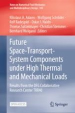
The resulting hot gas wall temperature profile is depicted in Fig. 6. The lower plot shows the axial wall temperature profile whereas the upper contour plot shows the circumferential temperature variation over the wall angle \(\Phi =\arctan \left( z/y\right) \). Black dashed lines indicate the position of the injection elements of the outermost row at \(-15\)°, \(-3\)° and 9°. In the throat (\(x=0\text {m}\)) a local circumferential temperature minimum in the wake of the injection elements can be observed due to locally increased hydrogen mass fractions. Furthermore, a locally reduced wall temperature can be noticed at the positions of the cooling channels, most pronounced at around \(x=-0.1 \text {m}\). Additional stratification due to local condensation of water can be seen in the supersonic part of the combustion chamber. The circumferential temperature stratification reaches a magnitude of up to 100 K which has to be considered in liner life analyses.
However, in addition to the circumferential stratification liquid rocket engine combustion chambers are also subjected to a high thermal gradient in radial direction due to the strong regenerative cooling. This can be recognized when Fig. 7 is considered where the local temperatures at several radial planes are plotted. The position of each plane is indicated in the sketch on the right where an axial section of a single cooling channel and fin is displayed. Starting with the strongly stratified hot gas wall temperature profile (a) already a significant temperature drop towards the cooling channel bottom wall (b) can be noticed. The circumferential stratification however remains nearly constant. Towards the upper cooling channel wall (c) and the copper-nickel interface (d) the structure temperature is reduced drastically and nearly reaches the coolant bulk temperature level. The circumferential stratification is strongly reduced.
Fig. 7
Structure temperatures of demonstrator TCD1 at different radial positions
×
Considering the coolant bulk temperature only a minor variation of about 1% can be noticed between the individual cooling channels. As in full-scale tests most experimental data on structure temperatures is obtained either on the combustion chamber’s outer wall or derived from few local thermocouples integrated in the wall a precise prediction of the maximum occurring hardware temperatures from experimental data is not possible. Well anchored numerical simulations can thus supplement experimental data and provide further insight.
4 Conclusion and Outlook
In the context of the SFB-TRR 40’s final funding period ArianeGroup has defined three virtual thrust chamber demonstrators to industry standard. These demonstrators have served as numerical test bed for all projects of the SFB-TRR 40. Furthermore, within project K4 the spray combustion and performance analysis tool Rocflam3 has been extended with a new CHT environment for fully three-dimensional analyses of full-scale liquid rocket combustion chambers unique within the SFB-TRR 40. Results for the upper stage demonstrator TCD1 have been presented and a strong circumferential variation of the hot gas wall temperature noticed. Due to the high radial temperature gradient this stratification is hard to measure and the relevance of CFD analyses as supplement to test is underlined.
The impact of the circumferential temperature stratification on thermo-mechanical behavior and resulting life of the thrust chamber has still to be assessed in future work. Also, additional injector patterns shall be investigated. Emphasis is placed on injectors with high mass flow elements as the resulting reduced element count is assumed to lead to increased circumferential stratification on the hot gas side. Moreover, an application of the CHT environment to main stage thrust chambers operating with \(\text {CH}_\text {4}\)/\(\text {O}_\text {2}\) as well as to kick stage thrust chambers operating with the commonly used storable propellant combination monomethylhydrazine (MMH)/nitrogen tetroxide (NTO) or novel “green” propellant combinations is foreseen. As for these propellants reaction kinetics play a vital role a novel timescale-based frozen non-adiabatic flamelet combustion model developed by Rahn et al.
[19, 20] will be applied.
Acknowledgements
Part of this work was performed within the National technology program TARES 2020. This program is sponsored by the German Space Agency, DLR Bonn, under contract No. 50RL1710. Cooperation within the SFB-TRR 40 is gratefully acknowledged.
Open Access This chapter is licensed under the terms of the Creative Commons Attribution 4.0 International License (http://creativecommons.org/licenses/by/4.0/), which permits use, sharing, adaptation, distribution and reproduction in any medium or format, as long as you give appropriate credit to the original author(s) and the source, provide a link to the Creative Commons license and indicate if changes were made.
The images or other third party material in this chapter are included in the chapter's Creative Commons license, unless indicated otherwise in a credit line to the material. If material is not included in the chapter's Creative Commons license and your intended use is not permitted by statutory regulation or exceeds the permitted use, you will need to obtain permission directly from the copyright holder.