Top

1994 | Book

Laboratory Manual for Electronics via Waveform Analysis

Author: Edwin C. Craig

Publisher: Springer New York

insite
SEARCH

About this book

To the Instructor The purpose of this laboratory manual is not just to help students to set up electronic circuits that function as they should. The important thing is the electronic concepts that the student learns in the process of setting up and studying these circuits. Quite often a student learns more electronics when he has to trouble shoot a circuit than when the circuit performs as it should when first built. It is unlikely that any students would be able to complete all of these experiments in one semester. The author believes that all students should have laboratory experiences with power sup­ plies, amplifiers, oscillators, and integrated circuits. Additionallabomtory experiments should be de­ termined by the instructor. Therefore, you can choose those that you want done. Some students are more efficient in the labomtory than others. Therefore, some would be able to complete more exper­ iments in a semester than others. Also many of these experiments cannot be completed in one two­ hour laboratory period. If space is available, the circuits could be left intact from one period to the next. Or you might want to select steps in an experiment that you want to delete. Neither the val­ ues of the components or the magnitudes of the power supplies, as given in the instructions, are critical. Therefore you could in most cases change them if the ones recommended are not available.
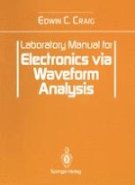
Table of Contents

Frontmatter
Introduction
Abstract
The purpose of this laboratory manual is not just to help students to set up electronic circuits that function as they should. The important thing is the electronic concepts that the student learns in the process of setting up and studying these circuits. Quite often a student learns more electronics when he has to trouble shoot a circuit than when the circuit performs as it should when first built.
Edwin C. Craig
1. Half-Wave Power Supplies
Abstract
1.
Transformer: 115 V primary and a center-tapped secondary, with a full secondary voltage of less than 20 V.
 
2.
Diodes: Four silicon rectifier. Only one will be needed in the half—wave power supply.
 
3.
Capacitors: Three electrolytic with voltage ratings of 50 V or more, one of 50 µ F or less, and two of 200 µF or more.
 
4.
Resistors: Two of any value from 1 to 20 kΩ and power ratings of 5 W (watts) or more.
 
5.
Alligator clips: Ten or more spring loaded clips, or other devices to connect the components in the circuit. The leads on the components used in these experiments have diameters too large to use with solderless breadboards.
 
Edwin C. Craig
2. Full-Wave Power Supplies
Abstract
The components needed for this experiment are the same as for the half-wave rectifier but two silicon diodes will be needed and the center tap of the transformer will be used.
Edwin C. Craig
3. Full-Wave Bridge Power Supplies
Abstract
The same as in Experiment 2 but four silicon diodes will be needed.
Edwin C. Craig
4. JFET Amplifiers
Abstract
Before building, testing, and studying amplifiers, that use junction field effect transistors, in the laboratory we need to have a general discussion of laboratory procedures when working with amplifiers.
Edwin C. Craig
5. BJT Amplifiers
Abstract
Use the oscilloscope to determine that the input signal is applied to the base terminal of the transistor. If a signal is present at the base but not at the collector then use a high impedance voltmeter to measure the dc voltages in the following order.
Edwin C. Craig
6. Two-Stage (NPN and PNP) Common-Emitter Amplifier
Abstract
1.
Transistor: One pnp power transistor or any other pnp transistor that can be used as an amplifier, for example, 2N3613,2N4403.
 
2.
Resistors: One 68 kΩ, one 10 kΩ, one 680 Ω, and one to be determined experimentally.
 
3.
Capacitors: One 47 (or more) µF (electrolytic), and one 0.1 µF (nonelectrolytic).
 
4.
Resistor substitution box.
 
Edwin C. Craig
7. NPN Emitter Follower
Abstract
1.
Transistor: One npn, for example, 2N2925 or 2N2712 or similar amplifier or general purpose transistors.
 
2.
Resistors: One 680 kΩ, one 10 kΩ, one 1 kΩ, and one to be determined experimentally.
 
3.
Capacitors: One 0.1 µF (nonelectrolytic) and one 10 µF or more (electrolytic).
 
Edwin C. Craig
8. JFET Differential Amplifier
Abstract
1.
Transistors: Two N-channel JFETs, for example, MPF 102 or MPF 112.
 
2.
Resistors: Two 1 MΩ, two 4.7 kΩ, and one 470 Ω.
 
3.
Potentiometer: One 2 kΩ.
 
4.
Capacitors: Two 0.1. µF (not electrolytic).
 
Edwin C. Craig
9. Push-Pull Amplifiers
Abstract
1.
Transistors: Three similar npn BJTs, for example, 2N2925, 2N2924, or 2N2712.
 
2.
Resistors: One 680 kΩ, two 3.3 kΩ, two 1 kΩ, two 680 Ω, and one to be determined experimentally.
 
3.
Capacitors: Three 0.1 µ F (not electrolytic).
 
4.
Potentiometers: Two 100 kΩ.
 
5.
Output transformer: Transistor push-pull type. Two identical ordinary output transformers, without center-tapped primaries, could be used if connected in series. In that case the junction between the two primaries of the transformers would serve as the center tap. The secondaries of the two transformers would be connected in series and serve as one secondary. These secondaries would have to be connected in series in such a way that the output voltages would be in series.
 
6.
Power supply: One that puts out both polarities of dc voltage of equal magnitudes of about +15 and -15 V. Four 9-V transistor batteries, connected in series with the middle junction grounded, could be used. All dc voltages, including the base voltages for Q2 and Q3, can be taken from one power supply.
 
7.
Resistor substitution box.
 
8.
Function generator: Or other sine wave generator.
 
Edwin C. Craig
10. Transistorized Wien-Bridge Oscillator
Abstract
1.
Transistors: Two JFETs, for example, MPF 102 or MPF 112.
 
2.
Resistors: Two 3.3 MΩ, two 220 kΩ, two 4.7 kΩ, and two 470 Ω.
 
3.
Capacitors: Two 47 µF (electrolytic), two 470 pF (not electrolytic, and one 0.1 µF (not electrolytic).
 
4.
Potentiometer: One 100 kΩ.
 
Edwin C. Craig
11. Colpitts Radio Frequency Oscillator
Abstract
1.
Transistor: One npn BJT transistor, for example, 2N2925, 2N2924, or 2N2712.
 
2.
Resistors: One 680 kΩ, one 68 kΩ, one 1 kΩ, and one 47 kΩ.
 
3.
Resistor substitution box or linear taper 100 kΩ potentiometer.
 
4.
Capacitors: Two 470 pF, one 0.1 µF (not electrolytic), and two 10 to 100 µF (electrolytic).
 
5.
Copper magnet wire: approximately 22 feet, per lab group, of No. 30 (enamel covered with a varnish-like material).
 
6.
Coil core: One Bic or other slender ball point pen with the tip and ink tube removed to serve as the core of the inductance.
 
7.
One nail or piece of iron or steel wire that would fit inside the ball point pen that is used as the core of the inductance.
 
8.
An rf oscillator: One with variable frequency will be needed for one step in the experiment. If none is available, that step could be omitted.
 
Edwin C. Craig
12. Measurement of Unknown Frequencies
Abstract
1.
A source of frequency to be measured. You could use the Colpitts oscillator that you built in experiment 11.
 
2.
A variable frequency rf generator.
 
3.
An audio amplifier.
 
Edwin C. Craig
13. Printed Circuit Boards
Abstract
1.
One light-sensitive copper coated (on one side) printed circuit board about 3.5 inches long and 2.5 inches wide.
 
2.
No. 2 photoflood lamp.
 
3.
Chemicals: Trichloroethylene, ferric chloride, and acetone (most finger nail paint removers contain acetone).
 
4.
Drill bit: size number 68 to 64 (diameter 0.031 to 0.036 inch).
 
5.
A mechanical stirrer is helpful but not necessary.
 
6.
A dark well-ventilated area during part of the process.
 
7.
The list of materials needed for the circuit to be mounted on the printed circuit board can be found at the beginning of the next experiment.
 
Edwin C. Craig
14. Astable Multivibrator
Abstract
1.
Transistors: Two npn BJTs, for example, 2N2925, MPS2222A or any general purpose npn transistor.
 
2.
Resistors: Two 2.7 kΩ, two 330 kΩ (these values are not critical but each pair should be two with the same values).
 
3.
Capacitors: Two 220 pF (these values are not critical but should be two with the same values).
 
4.
One 9-V transistor battery and one clip-on connecter for this battery.
 
Edwin C. Craig
15. RC Differentiating Circuits
Abstract
1.
Capacitors: One 0.1 µF and one 470 pF.
 
2.
Resistors: One 4.7 kΩ and/or a resistor substitution box.
 
3.
Diode: One germanium signal diode.
 
Edwin C. Craig
16. RC Integrating Circuits
Abstract
1.
Capacitor: One 0.1 µF.
 
2.
Resistors: One 100 kΩ, one 10 kΩ and one 1 kΩ. A resistor substitution box can be used instead of these resistors.
 
Edwin C. Craig
17. Schmitt Trigger Circuits
Abstract
1.
Transistors: Two npn BJTs, for example, 2N2925, MPS2222A, or any general purpose npn BJT transistor.
 
2.
Resistors: One 33 kΩ, one 10 kΩ, three 6.8 kΩ, one 4.3 kΩ, and one 330 Ω.
 
3.
Capacitors: One 0.22 µF and one 0.01 µF.
 
4.
Potentiometer: One with any resistance from 10- to 100-kΩ.
 
Edwin C. Craig
18. Integrated Circuit Operational Amplifiers
Abstract
1.
Integrated circuit: One 741 operational amplifier.
 
2.
Resistors: Two 100 kΩ, two 10 kΩ, and four 1 kΩ.
 
3.
Power supply: Two 9-V transistor batteries or any 9- to 15-V dual-polarity power supply.
 
Edwin C. Craig
19. Operational Amplifiers as Differentiators and Integrators
Abstract
1.
Integrated circuit: One 741 or other operational amplifier.
 
2.
Resistors: One 100 kΩ, two 10 kΩ, and one 270 Ω.
 
3.
Capacitors: One 0.1 µF and one 470 pF.
 
4.
Voltage sources: Two 9-V transistor batteries.
 
Edwin C. Craig
20. Waveform Generators
Abstract
1.
Integrated circuit: One ICL 8038 sometimes listed as 8038 CCPD, LM 566 CN, or some other waveform generator.
 
2.
Resistors: One 82 kΩ, one 22 kΩ, and two 1.5 kΩ.
 
3.
Capacitor: One 0.033 µF.
 
4.
Power supply: 10 to 30 V positive polarity.
 
Edwin C. Craig
21. Audio Power Amplifier
Abstract
1.
Integrated circuit: One IC 380, 383, 386, or 1877, or any other integrated circuit audio power amplifier.
 
2.
Resistors: Depends on amplifier selected. None for the 380 IC.
 
3.
Capacitors: One 0.47 µF and one large capacitance, for example, 100 µF, or greater, are recommended for the 380 IC.
 
4.
Power supply: 6 to 24 V (positive polarity). Two 9-V transistor batteries, connected in series, could be used instead of this power supply.
 
5.
Loud speaker: A small one made for transistorized circuits. A headphone could be used.
 
Edwin C. Craig
22. The Hall Effect
Abstract
1.
One Hall probe.
 
2.
Amplifier: One voltage amplifier, for example, 741 IC or other integrated circuit operational amplifier.
 
3.
Resistors: Two 2 kΩ, two 100 kΩ, and one 1 kΩ.
 
4.
Potentiometer: One 10 kΩ.
 
5.
Power sources: Two 9-V transistor batteries, one 6-V battery, and a low voltage (variable) dc source (see p. 122). You can use a dc power supply with a variable voltage ac transformer.
 
6.
Milliammeter: One that can be used at about 200 mA.
 
Edwin C. Craig
23. Standing Waves On Twin-Lead Transmission Lines
Abstract
1.
Radio frequency generator with a range up to at least 50 MHz.
 
2.
Electrical wire: Number 12 or 14 gauge house wire long enough to reach across the laboratory.
 
3.
Voltmeter: One high impedance analog meter with a dc voltage range down to a fraction of a volt, for example, an FET meter.
 
4.
Diode: One germanium signal diode.
 
5.
Resistor: One 470 Ω if using number 14 wire; 430 Ω if using number 12 wire.
 
6.
Bolts and nuts: Number 32 size; four bolts, eight washers, four nuts, and four screw eyes.
 
7.
Scrap lumber: A short piece of 1 x 4 board.
 
Edwin C. Craig
Metadata
Title
Laboratory Manual for Electronics via Waveform Analysis
Author
Edwin C. Craig
Copyright Year
1994
Publisher
Springer New York
Electronic ISBN
978-1-4612-2610-9
Print ISBN
978-0-387-94136-3
DOI
https://doi.org/10.1007/978-1-4612-2610-9