
Abstract
In order to study the mechanism of confined water inrush from coal seam floor, the main influences on permeability in the process of triaxial seepage experiments were analyzed with methods such as laboratory experiments, theoretical analysis and mechanical model calculation. The crack extension rule and the ultimate destruction form of the rock specimens were obtained. The mechanism of water inrush was explained reasonably from mechanical point of view. The practical criterion of water inrush was put forward. The results show that the rock permeability “mutation” phenomenon reflects the differences of stress state and cracks extension rate when the rock internal crack begins to extend in large-scale. The rock ultimate destruction form is related to the rock lithology and the angle between crack and principal stress. The necessary condition of floor water inrush is that the mining pressure leads to the extension and transfixion of the crack. The sufficient condition of floor water inrush is that the confined water’s expansionary stress in normal direction and shear stress in tangential direction must be larger than the internal stress in the crack. With the two conditions satisfied at the same time, the floor water inrush accident will occur.
1 Introduction
Water inrush from coal seam floor is one of the main problems for coal industry sustainable development in North China coalfields, which is more and more serious with the increase of mining depth. In the study of water inrush mechanism, scholars have carried out a lot of research work and proposed water inrush theory and criteria such as water inrush coefficient method (Peng et al. 2003), water inrush critical index method, “lower three zone” theory (Li 1999), in situ tensile and zero failure theory (Wang et al. 1994), board model theory (Zhang and Wang 2006), key strata theory (Qian et al. 1996), mutation and nonlinear model (Yang et al. 2001, 2005), water inrush advantage theory, water inrush power information theory, strong seepage theory (Ye and Liu 2005), similar theory, rock-water stress theory and so on, and formed water inrush prevention and control methods such as waterproof coal pillar mining (Jiang et al. 2008), double down (Miao et al. 2008, 2009), bottom grouting etc. Some scholars studied the change of rock permeability in the process of rock deformation and failure through rock stress and permeability coupling experiment (Oda et al. 2002; Noiriel et al. 2010; Watanabe et al. 2011). At present, these research results play a positive role in guiding the control of water inrush from coal seam floor. But there are some obvious weaknesses such as studying the rock and water separately or directly considering the confined water pressure to be hydrostatic pressure to floor, ignoring the interaction between seepage field and stress field. The essence of floor water inrush is the result of the interaction between seepage field and stress field and will lead to the extension and transfixion of the crack, which has been ignored. Scholars both at home and abroad have been doing extensive and in-depth research for the evolution rules of stress, strain and permeability in the process of rock seepage experiment. Some articles have presented the rock coupling seepage rule through experiments (Zheng et al. 1999; Zhu and Liu 2002) and summed up the empirical formula between rock permeability characteristics and effective stress. But there are few literatures overall considering the main permeability influence factors, the crack extension rule and the ultimate destruction form.
Considering the above weaknesses, the paper established a floor water inrush mechanical model based on triaxial seepage experiments, analyzed the main influence factors and the ultimate destruction forms of the rock specimens, studied the stress condition when the floor water inrush occur, and put forward the practical criterion on floor water inrush.
2 Triaxial seepage experiment
The triaxial seepage experiment, which obtained the stress–strain and strain-permeability curves, was carried out with the MTS815.02 electro-hydraulic servo system. The rock samples were shaped in cylinder specimens with diameter of 50 mm and height of 80–100 mm. The rock specimens were dealt with water saturation. The basic physical properties of three type rock specimens are shown in Table 1.
Confining pressure and pore pressure were set to 4.0 and 3.8 MPa separately (pore pressure is always lower than the confining pressure). The hydraulic pressure difference between two ends of the test specimen is 1.5 MPa. In order to fully consider the influence of heterogeneity of rock material on the test result, six rock specimens were tested. The part of rock permeability curve during the experiment is shown as Fig. 1.

Stress–strain and strain-permeability curves of rock specimens
3 Crack extension rule and ultimate destruction form
From the result of the experiment, the permeability of the three rock specimens happened mutation, which can be viewed as water inrush from coal seam floor. The permeability mutation location of siltstone is in strain softening stage. But the permeability mutation location of N-limestone and limestone are near the peak stress. The differences of permeability mutation locations reflect the differences of stress state and crack extension rate when the rock internal crack begins to extend in large scale, which will lead to different ultimate destruction forms.
Based on the triaxial seepage experiment, we studied the crack extension rule and the ultimate destruction forms due to the combined action of stress and seepage. Splitting force is applied to rock specimen by water flow during the seepage experiment, which can be shown by the distribution water pressure P. The distribution water pressure is applied to micro crack surface of rock specimen. According to the theory of rock mechanics and fracture mechanics, the crack extension mechanical model (as shown in Fig. 2) was established to analyze the crack extension rule and the ultimate destruction forms.

Crack extension mechanical model
Assuming the crack length in the above model is 2L, the angle between the long axis direction of crack and the maximum principal stress σ1 is β, the pore water pressure in the crack is P, then the normal stress and shear stress in the crack can be expressed as:
Further consolidation of Eq. (1) can get
Based on the previous research results, the main force leading to crack extension is the normal stress σ. In the experiment, the confining pressure σ3 is a constant, and σ3 < σ1. When the maximum principal stress σ1 is a fixed value, we can gain conclusion as follows:
-
(1)
For cracks with an angle 0° ≤ β<45°. Owing to 1 – cos 2β > 0, σ3–σ1 < 0, the larger of β, the greater of σ, cracks are more easily to close with compressive stress; the smaller of β, cracks are more easily to open with tensile stress.
-
(2)
For cracks with an angle 45° ≤ β ≤ 90°. Owing to –1 ≤ cos 2β ≤ 0, σ3–σ1 < 0, the larger of β, the greater of (σ3 – σ1) cos 2β/2, and then the greater of σ, cracks are closed more tightly with increased compressive stress.
Above analysis shows that the axial crack is easier to extend than lateral crack, and the smaller of the angle β, the easier for the cracks to extend. Before the stress reach the peak stress, the value of σ is also increasing along with the increase of σ1, and the crack is harder to extend, which explains the reason that the rock specimens’ permeability is decreased or vibrated. Due to the axial crack easier to extend than lateral crack, the rock specimens show splitting failure in axial direction after the peak stress. Even if it occurs shear failure, the value of β is always less than 45°, as shown in Fig. 3 (The siltstone specimen occurs shear failure, and the value of β is 24°. The N-limestone specimen and limestone specimen occur splitting failure).

Rock specimens failure forms
4 Single crack extension mechanical model of floor water inrush
In the stress–strain and strain-permeability curves of rock specimens, the permeability occurs “mutation” phenomenon. The mutation position of siltstone is located in the stress-relaxed area. The mutation positions of limestone and N-limestone are both located near the peak stress area. The differences of rock permeability mutation position reflect the differences of stress state and crack extension rate which can lead to floor water inrush. Based on the coupling mechanism of stress field and seepage field (Chai et al. 2003), the confined water mainly produces two kinds of mechanical effects on the crack surface:
-
(1)
The confined water makes the crack surface occur the pull-tensile effect, namely the seepage pressure of water flow in crack generates the normal expansion effect for crack surface (Chang et al. 2004; Si et al. 2005).
-
(2)
The structural plane and backfill of the crack occur deformation and displacement in the direction of water flow with the effect of hydrodynamic pressure. The structural plane of crack occurs shear extension (Sun et al. 2007). Therefore, single crack extension mechanical model of floor water inrush can be established according to laboratory triaxial seepage experiment, as shown in Fig. 4. We can regard the “mutation” phenomenon in the triaxial seepage experiment as occurring floor water inrush.
Fig. 4 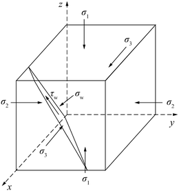
Single crack extension mechanical model

In Fig. 4, σ1, σ2, σ3 are the three principal stresses along three axes, \(\sigma_{\text{W}}\), \(\tau_{\text{W}}\) are the normal expansion stress and shear stress of water flow along the crack plane. The above model can be separated along the crack plane. We can regard the mechanical action of water flow as the boundary condition of the tetrahedral model, as shown in Fig. 5.

Stress state of tetrahedron
According to the Cauchy’s Law,
-
(1)
Without considering the seepage effect of confined water, the stresses of the separate unit applied on the crack plane are.
$$\left\{ \begin{aligned} \sigma_{n} &= \sigma_{1} l^{2} +\, \sigma_{2} m^{2} + \,\sigma_{3} n^{2} \\ \tau_{n} &= l^{2} m^{2} (\sigma_{1} - \sigma_{2} )^{2} + \, m^{2} n^{2} (\sigma_{2} - \sigma_{3} )^{2} + \,n^{2} l^{2} (\sigma_{3} - \sigma_{1} )^{2} \\ \end{aligned} \right.$$(3) -
(2)
Considering the seepage effect of confined water, the normal expansion stress is σ W , the shear stress is τ W , the stresses of the separate unit applied on the crack plane are.
$$\left\{ \begin{aligned} &\sigma_{W} + \sigma^{\prime}_{n} \; \ge \; \sigma_{1} l^{2} + \sigma_{2} m^{2} + \sigma_{3} n^{2} \\& \tau_{W} + \tau^{\prime}_{n} \,\ge\, l^{2} m^{2} (\sigma_{1} - \sigma_{2} )^{2} + m^{2} n^{2} (\sigma_{2} - \sigma_{3} )^{2} + n^{2} l^{2} (\sigma_{3} - \sigma_{1} )^{2} \hfill \\ \end{aligned} \right.$$(4)
The following equation can be obtained from the relationship between rock and water.
where l, m, n are the direction cosine of the inclined plane and the three coordinates respectively. \(\sigma_{n}^{\prime}, \tau_{n}^{\prime}\) are the stress which applied on the inclined plane by the separate unit.
The reason of rock permeability mutation is that the rock permeability increases suddenly. For a certain crack, the confined water head in crack surface is a constant value. When \(\sigma_{n}^{\prime} \neq 0\) and \(\tau_{n}^{\prime} \neq 0\), although cracks have been connected, rock permeability will not increase. Rock permeability may decrease with the stress increase. The mutaion position may appear in the strain softening stage (see Fig. 1). The above phenomenon shows that the extension and transfixion of the crack is only the necessary condition of rock permeability mutation. The confined water’s expansionary stress in normal direction and shear stress in tangential direction must be larger than the internal stress in the crack, which is the sufficient condition of rock permeability mutation. So, we can obtain the sufficient condition of rock permeability mutation as:
According to Griffith strength theory, crack extension is mainly caused by normal tensile stress, the shear stress and the physical and chemical effect of the crack water is very limited, with Eq. (5) the sufficient condition can be simplified as,
5 Mechanism and criteria of floor water inrush
Water inrush from coal seam floor is not only related to the mine pressure, but also determined by the relationship between stress state and confined water pressure. Water inrush accident will not happen, unless the following conditions are met at the same time.
-
(1)
The cracks in coal seam floor are extended and connected. Due to the interaction of mine pressure and confined water pressure, cracks begin to extend and connect, which is the necessary condition of floor water inrush.
-
(2)
The normal stress and shear stress of confined water on the crack surface are larger than the internal mine stress, which means \(\sigma_{n}^{\prime} = 0\)and \(\tau_{n}^{\prime} = 0\). This is the sufficient condition of floor water inrush.
According to the elastic–plastic mechanics and fracture mechanics theory, and combining with the mine pressure theory, the height of transmission fissure zone can be calculated as follow:
where, h C is the height of transmission fissure zone; H is the mining depth; γ is the density of the rock; L is the length of working face; R c is the compressive strength of floor rock mass, generally 0.15 times of the uniaxial compressive strength of rock.
Based on the rock uniaxial compressive experiment, the crack may extend if the angle between the crack axle and the compressive stress direction is less than 60° (β ≤ 60∘), otherwise the crack extension direction will not along the original crack direction. For safety reasons, we take β = 0∘, and the angles between crack extension direction and middle stress and between crack extension direction and the minimum principal stress are all 45°, namely take l = 0 \(m = {{\sqrt 2 } \mathord{\left/ {\vphantom {{\sqrt 2 } 2}} \right. \kern-0pt} 2}\), \(n = {{\sqrt 2 } \mathord{\left/ {\vphantom {{\sqrt 2 } 2}} \right. \kern-0pt} 2}\) in Eq. (7), which can be simplified as
Criteria of water inrush from coal seam floor is
where, σU2, σU3 are principal stresses of floor after unloading. The h F is the height between the coal seam and the confined water.
Criteria of floor water inrush is as follows,
-
(1)
If h C < h F , no inrush;
-
(2)
If h C ≥ h F , and \(\gamma_{w} (h - z) < (\sigma_{U 2} + \sigma_{U 3} )/2\), no inrush;
-
(3)
If h C ≥ h F , and \(\gamma_{w} (h - z) \ge (\sigma_{U 2} + \sigma_{U 3} )/2\), inrush will occur.
6 Engineering practice
The average incline length of No. 1513 working face is 165 m. The average thickness of coal seam is 1.8 m. The mining depth is from 482.9 to 555.2 m (average 520 m). With the above water inrush criteria, the broken depth of coal seam floor can be can calculated,
As the distance from pulverin aquifer to the floor is about 24 m, and the distance of Ordovician limestone karst aquifer to the floor is about 64 m, the fissure zone height of floor is larger than the distance to pulverin aquifer, but smaller than the distance to Ordovician limestone karst aquifer. So, coal mining may cause water inrush from pulverin aquifer, but not Ordovician limestone karst aquifer. In the process of practical mining, the water inflow is small, which reflects the validity of necessary and sufficient water inrush criteria.
7 Conclusions
-
(1)
The rock permeability “mutation” phenomenon reflects the differences of stress state and cracks extension rate when the rock internal crack begins to extend in large scale, which provides the theoretical basis for water inrush without premonition.
-
(2)
The crack extension and the ultimate destruction form of the rock in the process of percolation experiment are not only related to the rock lithology, but also related to β and σ P /σ3.
-
(3)
The water inrush mechanical mechanism is obtained through analyzing the water inrush mechanical model. The necessary condition of floor water inrush is that the mining pressure leads to the extension and transfixion of the crack. The sufficient condition of floor water inrush is that the confined water’s expansionary stress in normal direction and shear stress in tangential direction must be larger than the internal stress in the crack.
-
(4)
The criteria of floor water inrush are obtained. The floor water inrush accident will not occur, unless it satisfies h C ≥ h F and \(\gamma_{w} (h - z) \ge (\sigma_{U 2} + \sigma_{U 3} )/2\) at the same time.
References
Chai JR, Wu YQ, Yuan JG (2003) Double mechanical effects of fissure flow on fissure walls. Rock Soil Mech 24(5):514–517
Chang ZX, Zhao YS, Hu YQ, Yang D (2004) Theoretic and experimental studies on seepage law of single fracture under 3D stresses. Chin J Rock Mech Eng 23(4):620–624
Jiang YJ, Li B, Wang G, Li SC (2008) New advances in experimental study on seepage characteristics of rock fractures. Chin J Rock Mech Eng 28(12):2377–2386
Li BY (1999) Down three zones in the prediction of the water inrush from coalbed floor aquifer-theory, development and application. J Shandong Inst Min Technol (Nat Sci) 18(4):11–18
Miao XX, Pu H, Bai HB (2008) Principle of water-resisting key strata and its application in water-preserved mining. J China Univ Min Technol 1(37):1–4
Miao XX, Li SC, Chen ZQ (2009) Bifurcation and catastrophe of seepage flow system in broken rock. J China Univ Min Technol 19(1):1–7
Noiriel C, Renard F, Doan M-L, Gratier J-P (2010) Intense fracturing and fracture sealing induced by mineral growth in porous rocks. Chem Geol 269(3):197–209
Oda M, Takemura T, Aoki T (2002) Damage growth and permeability change in triaxial compression tests of Inada granite. Mech Mater 34(6):313–331
Peng SP, Meng ZP, Wang H, Ma CL, Pan JN (2003) Testing study on pore ratio and permeability of sandstone under different confining pressures. Chin J Rock Mech Eng 22(5):742–746
Qian MG, Miao XX, Xu JL (1996) Theoretical study of key stratum in ground control. J China Coal Soc 21(3):225–230
Si HB, Yang WM, Wu WJ, Xu H (2005) The model of fracture mechanics of water bursting from coal seam floor. J Beijing Vocat Tech Inst Ind 4(3):48–50
Sun YL, Shen ZZ, Wu YJ (2007) Analytic model for crack propagation under coupled mechanical-hydrological environment. J Hydraul Eng 10:334–339
Wang ZY, Liu HQ, Wang PY, Yu SC (1994) Theory and practice of coal mining discipline on confined water. J China Coal Soc 19(1):40–48
Watanabe N, Ishibashi T, Ohsaki Y, Tsuchiya Y, Tamagawa T, Hirano N, Okabe H, Tsuchiya N (2011) X-ray CT based numerical analysis of fracture flow for core samples under various confining pressures. Eng Geol 123(4):338–346
Yang TH, Tang CA, Zhu WC, Feng QY (2001) Coupling analysis of seepage and stresses in rock failure process. Chin J Geotech Eng 23(4):489–493
Yang TH, Tu XL, Yu B, Zhang YB, Li LC, Tang CA, Tan GH (2005) A micromechanical model for simulating the coupling of fracture and flow of rock. Acta Mech Solida Sin 26(3):333–337
Ye YX, Liu GY (2005) Research on coupling characteristics of fluid flow and stress within rock. Chin J Rock Mech Eng 24(14):2518–2523
Zhang JC, Wang JX (2006) Coupled behavior of stress and permeability and its engineering application. Chin J Rock Mech Eng 25(10):1981–1989
Zheng SH, Zhao YS, Duan KL (1999) An experimental study on the permeability law of natural fracture under 3-D stresses. Chin J Rock Mech Eng 18(2):133–136
Zhu ZD, Liu LM (2002) Experimental research on complete stress-strain process seepage characteristic of brittle rock. Rock Soil Mech 23(5):555–563
Acknowledgments
The program was supported by the Youth Innovation Fund of China (KJ-2013-TDKC-15) and the Fostering and Doctor Startup Initial Fund Program of Xi’an University of Science and Technology (201350; 2014QDJ033).
Author information
Authors and Affiliations
Corresponding author
Rights and permissions
Open Access This article is distributed under the terms of the Creative Commons Attribution License which permits any use, distribution, and reproduction in any medium, provided the original author(s) and the source are credited.
About this article

Cite this article
Pang, Y., Wang, G. & Ding, Z. Mechanical model of water inrush from coal seam floor based on triaxial seepage experiments. Int J Coal Sci Technol 1, 428–433 (2014). https://doi.org/10.1007/s40789-014-0049-7
Received:
Revised:
Accepted:
Published:
Issue Date:
DOI: https://doi.org/10.1007/s40789-014-0049-7