
Abstract
This paper proposes a new safety framework and platform for the functions of future electrical/electronic (E/E) systems. The framework aims to cope with the increasing complexity of the E/E systems, and to enhance their flexibility, but retain the safety properties and keep low engineering costs. A domain-specific meta-model is used to specify relevant aspects of the system such as component interface requirements and function descriptions. The meta-model is used in a tool that generates data structures, which are then used to configure the fault-management layer of the run-time environment. The fault-management layer preserves the safety properties of the system at run-time, by facilitating error detection and fault-handling mechanisms, and supporting controlled adaptation. By reusing already developed safety measures for different systems and functions, future development costs for non-functional qualities can be saved.
1 Introduction
Today’s E/E systems consist of growing number of interconnected and interacting computer subsystems. The increase in safety–critical software-based functions in these systems (e.g., increased software-based automated self-driving operation in vehicles), the growing networking subsystems and functions to each other (e.g., up to 100 interacting control units, sensors, actuators in a vehicle) lead to a continuous increase of system complexity. Integrating existing and new subsystems or system functions drive engineering costs. System failures in these safety–critical systems mainly arise in the interactions among subsystems rather than the failure of individual subsystems.
To cope with the complexity of these systems in the future, and to increase their flexibility and extensibility but retain the safety properties and keep low engineering costs, these systems have to be supported with a suitable development approach and extended to contain a run-time environment including configurable fault-management safety mechanisms. A model-based approach and a fault-management layer for a run-time environment, targeting the automotive domain is offered as a solution to the mentioned problems.
This paper is structured as follows. In Sect. 2, a short overview of the main features of a new scalable fault-tolerant E/E architecture that aims at targeting the before-mentioned problems is given. Section 3 presents the safety framework by explaining the meta-model and the fault-management of the run-time environment that is also part of the new E/E architecture. An evaluation of the presented approach and a rationale for the made assumptions is given in Sect. 4. Section 5 compares the approach against available solutions provided by industry and scientific community. The last section provides a brief summary and outlook.
2 Foundations of the new E/E platform-RACE
The challenges, mentioned before force a change of the E/E system architecture. A new architecture was developed in the robust and reliant automotive computing environment for future eCarsFootnote 1 project [1]. In RACE, the existing system architecture is replaced by a centralized platform computer (CPC) that executes all high-level functionalities (Fig. 1). In this architecture, sensors and actuators become smart but still responsible for the low level control tasks. These sensors and actuators are executing high-level control commands calculated by applications deployed on vehicle control-computers (VCCs), the electronic control units (ECUs) of the central platform computer. The interconnection of these smart components and the VCCs is done by a high-bandwidth Ethernet communication. One type of vehicle control computer is a duplex control computer (DCC). The main task of the DCC is to execute control functionality. To guarantee fail–safe, a DCC has two execution channels and both channels monitor input and output data mutually. In case of channel inconsistency, the faulty DCC backs out to not jeopardize the operation of a RACE system. A fail-operational behavior is guaranteed when at least a second DCC is provided that takes over the control tasks after the first one failed. Fail-operational behavior requires a redundant power supply (Fig. 1, blue and red) and redundant communication infrastructure for the redundant DCC controllers.

RACE system architecture: fail-operational design with central platform computer and smart sensors and actuators

DCC channel SW architecture concept
The software architecture of the centralized platform computer containing the run-time environment is designed with different components including the ones of the fault-management layer (Fig. 2, monitoring, detection, handling components). A data-centric approach, used by the run-time environment, enables the decoupling of applications from the infrastructure components i.e., the DCCs. Different predefined topics are used to represent various information of a vehicle, e.g., velocity or exterior temperature. These topics are used for the communication among software components over hardware boundaries. The set of possible topics in one system is predefined in a so-called Dictionary. The dictionary concept allows data compatibility between different subsystems and SW components, without requiring additional synchronization of interfaces.
Demanding safety–critical E/E systems such as vehicles operate under tight and hard real-time constraints. Therefore, critical system functions are scheduled in time-triggered manner under control of the internal clock rather than in event-triggered manner where external incidents can stress the system. This provides a safety–critical system a more deterministic behavior for the mission for which it was constructed and dimensioned. Thus, the SW components including also the run-time environment components in RACE are executed in cyclic manner (Fig. 2) with a defined duration, e.g., 10 ms. A flexible assignment of two or more SW components to computers is also supported by the RACE run-time environment, enabling easy integration of additional software functions. Support for mixed-criticality, meaning SW components with different safety criticality requirements can be executed on one control unit, is enabled by spatial and temporal separation provided by the PikeOS operating system.
3 Safety framework and platform
An overview of the safety-oriented framework and software platform targeting future E/E systems is given in this section. The approach workflow is summarized as follows:
A meta-model is defined, which allows function developers to explicitly specify and capture safety relevant aspects of the system such as component interface requirements and function descriptions. The meta-model is to be used by a model-driven development tool. The tool subsequently generates data that is used for configuration of- and at run-time by the safety platform i.e., fault-management layer. The fault-management layer preserves the safety properties of the system at run-time, by facilitating error detection and fault-handling mechanisms on function and on system level. The idea behind using a run-time environment approach is to reuse the already developed safety mechanisms for different systems and functions and save future development costs spent on non-functional qualities. By decoupling the system function logic from the safety mechanisms the development of complex functions is reduced.
3.1 Framework: modeling future E/E functions
The framework is based on modeling required information (e.g., subsystem interface requirements) so that fast and automatic error detection and fault-handling by the platform at run-time is possible. Therefore, the necessary meta-model (Fig. 3) for describing that information is explained below as previously described in Frtunikj et al. [2]. The model enables the composition of functions from different subsystems (HW and/or SW) and the definition of different service rules. This is the first step towards automated and uniform function description. With this description a.k.a. Manifest, the designer of functions and subsystems is able to specify the non-functional requirements and characteristics. For example, information such as: worst-case execution time (WCET), required memory, safety requirements as ASIL level etc., required and provided (subscriptions and publications) subsystem data are specified. Based on this information, the configuration for the fault-management layer of the run-time platform is generated.

Meta-models defining function and its composing subsystems
The composition of a system function is driven by the identification and specification of basic subsystems, and specification of the interactions across the subsystems, i.e., the linkages, that are needed to communicate the value and temporal information across the subsystems from which the aggregated system function results. The service level rules represent specification of the quality of a system function functionality after occurrence of failures of the subsystems from which the function is composed. The information about the integrity quality requirement is important for the health monitoring mechanisms that provide information required to determine the correct or faulty behavior of the subsystem and thereby of a function. The meta-model is used in an Eclipse-based model-driven development tool CHROMOSOME Modeling Tool (XMT).Footnote 2
System functions are grouped in set of system function clusters. All system functions on the top layer are grouped into clusters because functions with the same requirements on safety can be managed using the same algorithms and reconfiguration mechanisms. The grouping of system functions is based on the safety properties of the functions such as: (a) criticality level of the function [in the automotive standard called automotive safety integrity level (ASIL)]; (b) performance requirements regarding fail-operational or fail–safe behavior.
It is important to emphasize that each of the subsystems has configuration description that expresses additional restrictions, required to be considered at run-time. For example, if the subsystem is a sensor, the configuration description contains information such as sensor position, viewing direction, maximum distance, type of target or collision objects w.r.t. geometry and material data, etc. [3]. The information is used to check if the data from one type of sensor in case of failure can be replaced by the data from another type of sensor [4].
3.2 Software platform: fault-management layer for future E/E functions
Since vehicles are complex safety–critical systems, layered system design paradigm copes with such complexity by focusing on those aspects of the system that support the design activities at the corresponding level of abstraction. Therefore, a multi-layered SW architecture is offered in this paper in which a fault-management layer that guarantees the predefined safety properties at run-time, represents one of the layers (Fig. 4). The generic fault-management layer simplifies the development of complex vehicle functions by releasing the functionality from safety properties, and enables safe integration and execution of the vehicle functions.

Layered design
For realizing a fault-management layer that detects errors and handles faults, self-monitoring and self-healing control components are needed. These components supervise the system and initiate the adaptation during run-time in case of faults by using control loops. In the autonomic computing (AC) paradigm, the elements of the system are managed by control loops based on the so-called MAPE-K (monitor, analyze, plan, execute-knowledge based) cycle [5]. The control loop continuously monitors and analyzes the system and its environment and based on this information it plans the next steps and executes the planned actions. The different phases have access to a common knowledge base which provides information about the changes within the system or in the systems environment. Below an overview of the tasks that are executed in each MAPEK phase in the context of the presented approach is given.
Monitor In this phase the monitoring components of the run-time environment collect the error indication information of the managed components. The parameters, which need to be monitored, are given by the requirements specified in the meta-model, and are supervised by health monitoring subsystem of the run-time environment.
Analysis During this stage the error indications and the available information in the knowledge base are analyzed to determine the health state of each subsystem in the system, and assess whether an adaptation is required.
Plan The plan stage provides mechanisms that determine a set of actions (e.g., new configuration) required to adapt the system in order to maintain its safety properties.
Execute During this stage the planned actions are executed to transition the system into an improved or safer state. Additionally, extra artifacts created during the planning phase are added to the knowledge base and can be used when a new need for adaptation is detected.
An overview of the core concepts and components of the fault-management layer is given below. The MAPE phases i.e., the phases of error detection (health monitoring), consolidation of error indications, health state determination and fault-handling, and the mapping to components of the fault-management layer is depicted on Fig. 5.

Fault-management layer
3.2.1 Monitor and analysis: error detection and state management
A system function is considered as a composition of subsystems (Fig. 3 in Sect. 3.1). Since the subsystems have precisely specified interfaces in the domains of time and value, that information is used for configuring the safety mechanisms of the run-time system, which provide information and error indications required to determine the health state of the corresponding subsystems. The meta-model introduced before generates configuration information for the diverse safety mechanisms of the fault-tolerant layer, which are able to detect errors (i.e., deviation from a correct behavior) of subsystems at run-time. The information that the error detection mechanisms produce i.e., error indication (\(VALUE_{Indication}\) or \(TIME_{Indication}\)) can be mapped to the health state of the defined subsystems.
Each of the subsystem interfaces is specified in the two domains: the value a.k.a. content associated with the interface, and the time at which this content is presented. A value error (\(VALUE_{Indication}\)) happens when the content of the information delivered at the interface (i.e., the content) deviates from the specified one. When the time of arrival or the duration of the information delivered at the interface deviates from the specified one, a time error is detected (\(TIME_{Indication}\)).
A differentiation is made between detection of transient and permanent errors. This is done by introducing configurations of each error indicator which is configured individually based on the defined requirements. The configuration has the following information: increment, decrement, and threshold, as a three-tuple (increment, decrement, threshold). Whenever an error of a certain subsystem is registered at receiver side the error indication is incremented by increment value. As soon as the threshold is reached then the error of a system is confirmed i.e., recognized. In a case when the error is not present the error indication is decremented by decrement.
The subsystems represent modular fault-containment regions (FCR) [6] which are seen as black box w.r.t. error detection. Failure modes of FCRs are defined according to the effects appearing at the signal interface of an FCR. Therefore, the defined FCRs have precisely specified interfaces requirements, which are needed to detect anomalies (failures) at run-time. This means, in a case of a failure the FCR and with that the subsystem is marked and handled as faulty. The following relevant FCRs/subsystems are defined and they can be composed to form a system function:
-
Execution nodes (sensors and actuators with their corresponding SW computing units).
-
Application software components—SW functions implementing the system function control algorithm including its resource partition (time and space) in which it is running.
The above FCRs are strictly modular and encapsulated, which is important in order to uniquely restricts and assign the impact of a fault to a certain subsystem. Below a brief explanation of the error detection mechanisms is given. Moreover, it is shown how the information that they produce (error indications) can be mapped to the health state of the defined FCRs.
-
A.
Error detection.
The error detection approach is mainly based on error indications produced by safety mechanisms that detect errors of: (a) communicating FCR execution node or network element by analyzing error indication that are result of errors detected in Ethernet frames related to the sending FCR/subsystem. This failure is a result of a HW fault in the corresponding FCR; (b) local FCR computing unit by analyzing error indication produced by global tests preformed on that unit. This failure is a result of a HW fault in the corresponding FCR; (c) application software components by analyzing error indication produced by the operating system environment and application heath monitors. These errors are a result of a SW fault in that application software FCR. The error detection mechanisms forward their error indications to the Health Monitoring component of the fault-management layer.
Error detection of communicating subsystem Since it is assumed that execution nodes communicate only via exchange of messages, an error of a communicating node or a network element is discovered on the receiving node solely by message (a.k.a. frame) evaluation. A message can be incorrect in the value domain if the data field of the message contains a corrupted value. In addition, an incorrect message in the time domain is recognized if the message is sent at an unintended instant or not at all. All these errors can be detected by the safety mechanisms e.g., cyclic redundancy code (CRC) check in the receiving FCR/subsystem, provided the safety mechanisms have a priori knowledge about the correct behavior of a subsystem. Thus, correct behavior can be considered only in the case when the following quality characteristics can be recognized by the monitoring mechanisms: (a) correct timing—a message containing updated data is received in a previously defined time frame, (b) correct cyclic redundancy code—a CRC check of the complete frame is valid; (c) correct value—a message contains plausible data (valid data). In case a violation of any of the above-specified behavior is detected by the monitoring safety mechanisms, respective \(VALUE_{Indication}\) or \(TIME_{Indication}\) is updated.
Error detection of local subsystem Error indications that point to errors in the hardware parts of the local FCR execution unit is also taken into consideration. Therefore, the results of global tests such as periodic CPU tests, validation of ROM/Flash check-sums, memory tests, and hardware-assisted built-in self-test, update the error indication \(VALUE_{Indication}\) of the local FCR [15].
Error detection of application software components The error detection concept of application software components is built around various monitor components, tests, and plausibility checks, which report their status through setting the corresponding indications. Application-specific monitor is a specific supervisor developed for a concrete software component independently based on function specification [15]. Typical examples are plausibility checks developed by an independent team. This kind of monitor has read access to input data and internal state of the function and performs checks to ensure state consistency and transition correctness. Since we are dealing with a mixed critical system, meaning SW components with different criticality levels, i.e., ASIL, can be deployed and run on a same computing unit, time and memory partitioning is used to avoid interference between the functions. However, if an application violates the memory or timing resources allocated to it due to design faults, the application-independent safety mechanisms notify the fault (updates the \(VALUE_{Indication}\) or \(TIME_{Indication}\) of the application FCR).
-
B.
State management of fault-containment regions.
By analyzing the error indications at run-time the health state of each FCR is determined. The benefit of this kind of state management is the always deterministic state of all subsystems and with that of the complete system, which is essential w.r.t. safety. A differentiation between the following FCR states is made: (a) passive or isolated—deactivation or isolation FCR when an error is detected in order to prevent further error propagation; (b) active— transition of an FCR from a non-operation into a fully operational state. In case of a detection of permanent error, the FCR and the corresponding subsystem is isolated, in a case of transient error the FCR is passivated.
The information regarding the state a.k.a. health state of the defined FCRs is collected in state vector on each execution node and cyclically exchanged with the other health state vectors of the other execution nodes. In this way all execution nodes have the information about the health state of other node and with that of the whole system.
3.2.2 Plan and execute: system function service level determination and reconfiguration
To enable calculation and appropriate determination of system function (sf) service level at run-time, a run-time system component named system function manager (SFM) identifies the state of all subsystems belonging to all functions in the system. This means the SFM is able to determine the health state and the degradation level of all subsystems (subS), based on the actual subsystem state and the error indications that are result of the diagnosis of that specific subsystems.
Depending on the error indications that the health monitoring run-time system components generate and the redundancy type of the subsystem (e.g., single, double, triple redundancy etc.), the SFM identifies the health state and calculates the degradation level of each subsystem at run-time as presented in Frtunikj et al. [2]. Based on the states and the redundancy information, the following degradation level of the subsystems \(subSDeg_i ^ x\) are defined:
-
Degradation level 0 (\(subSDeg ^ 0\)): data available (no error detected and the subsystem health state is active)
-
Degradation level 1 (\(subSDeg ^ 1\)): data available but data coming via one network link in the previously mentioned system architecture are not available the subsystem health state is active)
-
Degradation level 2 (\(subSDeg ^ 2\)): data available but one redundant subsystem from same type is faulty (meaning lost) (the subsystem health state is active)
-
Degradation level N (\(subSDeg ^ N\)): data are not available due to a fault (the subsystem health state is isolated)
Certain system function sf can provide different level of service depending on the state and degradation level of the subsystems from which it is composed from. The information about the degradation level of each subsystem is used to calculate the level of service of a system function sfLoS at run-time. Since only the function developer has the knowledge and the expertise, which subsystems compose and are required for certain system function, he is responsible for defining the allowed service level of the system function. A service level rule for a system function is expressed by means of first-order logic using the meta-model (Fig. 3) introduced before. The expression includes all subsystems and their degradation state subSDeg. An example of such an expression for a system function consisting of three subsystems can look like:

An example system function sf in a vehicle is pedestrian detection and auto brake function that consists of four subsystems/FCRs: camera \(subS_{camera}\), radar \(subS_{radar}\), brake \(subS_{brake}\), and SW component implementing the algorithm for pedestrian detection \(subS_{pdswc}\). Each of these subsystems has different degradation levels depending on the redundancy constellation:
-
Camera: \(subSDeg_{camera} ^ 0\) and \(subSDeg_{camera} ^ N\)
-
Radar: \(subSDeg_{radar} ^ 0\), \(subSDeg_{radar} ^ 1\) and \(subSDeg_{radar} ^ N\)
-
Brake: \(subSDeg_{brake} ^ 0\) and \(subSDeg_{brake} ^ N\)
-
Pedestrian detection SW component: \(subSDeg_{pdswc} ^ 0\) and \(subSDeg_{pdswc} ^ N\)
The service level rules specified by the predicates define the dependency between the specific function and the sensors or actuators and other applications whose data are required in order the function to work. The system function degradation sfLoS can get values form 0 to N (0 lowest (fully functionality) level and N highest (no functionality) service level) which define the different service levels that the system functions can have.
Based on the service level rules and the actual degradation level \(subSDeg_i ^ x\) of each subsystems, the boolean expressions are evaluated at run-time and the “best” system function service level sfLoS is calculated. For the pedestrian detection and auto brake function the system function developer has specified the following degradation rules:

Figure 6 graphically sketches the service level 2 of the pedestrian detection system function.

Pedestrian detection and auto brake function \(sfLoS_{pedDet} ^ 2\)
3.2.3 Plan and execute: system level run-time reconfiguration
The main goal to be achieved by the reconfiguration is to improve the operational safety of the system also in case of faults while preserving the required safety properties. A reconfiguration can be considered in different scenarios such as [8]: (a) granularity level—reconfiguration is either performed at execution node or at partition level. For node level reconfiguration, a spare execution node is allocated to all SW applications running on the faulty computing node. For partition level reconfiguration, spare partitions running on non-faulty nodes are allocated to the applications running on the faulty computing node; (b) location—reconfiguration can be performed either locally or distantly on any module of the platform; (c) time—reconfiguration can be performed while the system runs or while it is stopped (e.g., vehicle driving or when the vehicle is stopped).
An important benefit of local reconfiguration over distant reconfiguration, is that it requires almost no reconfiguration of communication in comparison to the distant reconfiguration. The loss of system functions when the system is stopped has generally very little effect on safety. So it is likely to be much simpler to show the innocuity of reconfiguration on safety when it is performed when the system is stopped.
After error(s) are detected, its impact identified via the subsystem health state and exchanged via the health state vectors between the executing nodes, the reconfiguration manager component chooses one or multiple adaptation options:
-
Execute SW component belonging to a system function in a different partition—a system function SW component is instantiated on different partition on the same execution node.
-
Execute SW component belonging to a system function on different execution node—a system function SW components is instantiated on a different core node. In case the previous core node is defective, the node will also be isolated.
-
Run system function with different allowed service level—a system function is provided with fewer resources during execution and the adaptation is based on different execution paths of the function.
-
Deactivate system function–system function SW components are shut down.
It has to be emphasized that a clear distinction between an allocation strategy and a reconfiguration strategy is made. The allocation strategy should be done offline at design time or when the system is not running, and the reconfiguration steps concentrate on deactivation of low critical functions or start them in mode with lower service level at run-time. Therefore, to enable a fast reconfiguration during run-time and also do not jeopardize the safety and certifiability of the system, a set of so-called configuration allocation set (CAS) for each execution node is predefined during the development process or when the system is not running. Each CAS represents a fixed set of allocated functionalities which have to be provided in a particular context (e.g., system mode), resulting in a set of allocated system functions. The allocation of the SW components defined by the CAS is fixed; however, during run-time the reconfiguration manager decides about activation or deactivation of set of functionalities on a certain execution node (local reconfiguration). In case of an execution node failure, an offline analysis that determines and later allocates/loads new configuration allocation set (CAS) is done when the vehicle is in a stationary position. In this case of distant reconfiguration, the routing of the impacted switches must be also modified to ensure the required traffic. The offline analysis has access to the healthiness knowledge of the system and before each start of the vehicle it checks whether for all applications the correct level of redundancy is available. It must be possible to restore the minimum level of redundancy by moving the applications running on the faulty module to a non-faulty one. If this is not the case the vehicle cannot be used and is not able to be started by the user.
The reconfiguration solution presented here is a distributed one. The Reconfiguration Manager component is distributed on each node. Each local manager independently realizes a local reconfiguration which communicates via the health state vector with the other local supervisors running on other nodes. Via the reconfiguration algorithm the best utilization of local resources with respect to specific system objectives (e.g., in this case the safety requirement) can be realized. The reconfiguration procedure is divided in three main steps:
-
A.
Triggering a reconfiguration.
When a computing node or a partition fails, a reconfiguration can be launched if this failure has an operational and safety impact. The monitoring and error detection function detects an error and sends this event to the reconfiguration manager. This happens in the Monitoring phase of the MAPEK cycle.
-
B.
Selection of a correct configuration at run-time.
When the failure is confirmed, the reconfiguration manager component must determine the current state of the system in order to define the next configuration (planing phase of the MAPEK cycle). Since each node has already allocated configuration allocation set (CAS) the algorithm explained below performs a local node reconfiguration at run-time. The proposed reconfiguration algorithm dynamically selects which software components of the (CAS) belonging system functions to be activated or deactivated in order to maximize the safety properties of the system and to ensure computing resources are conserved. Given the limited computational power and the requirement for timely response, the algorithm opts for approximate answers rather than optimal solutions, so that acceptable decisions can be decided quickly. As a result, the algorithm is similar and can be compared to a Greedy approximation algorithm.
The proposed three step algorithm is illustrated on Fig. 7. Step 1 is to choose the system function cluster based on the Cost Function 1 that should be present in the system in order to satisfy the safety properties/requirements. The cost function contains two variables (and two coefficients) that can influence the score of the function. The criticality variable ASIL (in the automotive system meaning automotive safety integrity level) can get values \(\left\{ 0, 1, 2, 3, 4\right\}\) for \(\left\{ QM, ASIL A, ASILB, ASIL C, ASIL D\right\}\) criticality level respectively. The PerformanceRequirement can be assigned values \(\left\{ 1, 2\right\}\) for \(fail-safe\) and fail–operational behavior respectively. First the clusters with the highest cost, meaning ASIL D and a performance requirement (fail–operational) is selected. For the two coefficients holds \(\lambda + \delta = 1\), and it is up to the system architect to decide upon their weight.
Step 2 selects the SW components that belong to the system functions of the selected cluster. Step 3 then ensures that all selected SW components are activated on one of the available execution units (DCC) and that constraints (enough memory and CPU resources) for a valid configuration hold. Failure of the activation results in a re-execution of previous step, with SW components that have smaller Cost Function 2 as a result of service level. The service level can be decided based on the allowed service level of the system functions. Normally, the inferior service levels require less hardware resources. As shown on Figure 7, the score is dependent on the three parameters and their corresponding weight coefficients. Despite of the required resources, the priority of the function, which states the importance (w.r.t. system safety) of the system function within the cluster (which can have values in range \([0-M]\) depending on the system specification), also has influence on the score of the Cost Function 2. Again, for the three coefficients holds the following \(\alpha + \beta + \gamma = 1\). Depending on the system requirements, the system architect may decide to modify the coefficients values.
Fig. 7 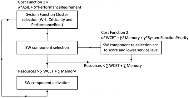
Reconfiguration algorithm
-
C.
Reconfiguration execution.
The last phase of the MAPEK cycle is the execution phase where the transition into an improved or safer state is executed. A reconfiguration is said to be safe if it satisfies some constraints. For instance, an application software component can be hosted on a module only if it provides adequate resources for the application such as processing power or memory. A reconfiguration transition is safe if the intermediate steps are safe (they do not impact the integrity of the vehicle) and the duration of the transition is bounded. Since only predefined configuration sets are used during run-time, the system may only exhibit predictable behavior. To provide a dependable transition between CAS, a transaction-based methodology is foreseen, considering the so-called ACID properties (atomicity, consistency, isolation and durability) [14]. These properties must be ensured by the mode change protocol, e.g., by including a roll-back mechanism. A failing transition might result in a predefined fall-back configuration. Unwanted and uncontrolled behavior is not admitted by this approach while enabling the adaptation of the system regarding safety properties.

4 Approach evaluation
One of the fundamental design principles of the presented approach is guaranteeing simplicity and expressiveness for the modeling and re-usability and complexity reduction for the fault-management layer. As showed in the previous section, the principles were applied to both aspects i.e., the modeling of safety requirements and properties of subsystems and system functions, and to the fault-management layer architecture. The main idea of the approach is to decompose safety into an expressive enough configuration specifications and reusable mechanisms of the fault-management layer. The separation contributes to reduction of the complexity of the system function since the fault-management layer preserves the safety properties of the system and its system functions at run-time.
However, some assumptions had to be made to make the approach generative and be feasible for practice. Below we identify these assumptions and discusses for each one, why it is reasonably made.
4.1 Assumptions: safety modeling framework
The specified meta-model is not able to capture arbitrary safety requirements, formulated in natural language. Moreover, the restriction to the value and time quality attributes of required and provided signals of each subsystem excludes the explicit modeling of some aspects of errors such as: correct, subtle incorrect, coarse incorrect and omission in the value domain and correctly timed, early, late and infinitely late in the time domain as defined by McDermid [10]. However, by offering configurations for each error indicator the aforementioned failure behavior is modeled. One might argue that the possible choices of value and time quality attributes are limiting the power of the approach to a set of general error classes, but they are a popular consensus in the research community.
4.2 Assumptions: safety platform
Decoupling of a transmitter and a receiver subsystem is assumed in the presented approach. In RACE, this is permitted by the usage of publish-subscribe paradigm. This kind of decoupling on functional level increases flexibility and offers the possibility to validate the data exchanged between transmitter and receiver directly into the fault-management layer. Therefore, the assumption is plausible and also used in other run-time environments such as the automotive AUTOSAR environment.
The approach assumes a time-triggered system such as RACE, where the error detection and state management mechanisms and the components of the fault-management layer can be scheduled with cycle-precision. Therefore, the safety platform, i.e., the fault-management layer cannot be ported to event-triggered systems without much effort. However, event-triggered systems are very rare in the domain of safety–critical systems especially because of the difficulty of demonstrating an execution determinism.
The approach also relies on an operating system that enables time and space partitioning to run applications with different safety and security levels on the same hardware, protected from each other. PikeOSFootnote 3 is a platform that provides these kind of partitioning and which is used in the RACE demonstrators i.e., test rack and test vehicle. The targeted hardware platform which is used in RACE is ARM®dual-core Cortex-A9 MPCore processor on which PikeOS was running.
In the automotive industry, software components assigned to an ECU cannot be easily transferred to other devices after they have been deployed. This is because today’s E/E architecture has a dedicated ECU for each system function for safety and certification reasons, which results in huge complexity. However, with the introduction of the RACE architecture different software components can be deployed to one control unit (DCC) and in case of a resource scarcity highly safety–critical SW components can be transferred to another control unit.
The execution of reconfiguration is currently only in a basic prototypical phase where the so-called ACID properties are not guaranteed. Thus, already established results from other research groups developing transaction-based methodologies have to be included in the future.
5 Related work
A lot of modeling languages exist in academia and industry that are dealing with the questions modeling. Systems modeling language (SysML) [11] is a general purpose graphical modeling language for representing any kind of system. The UML2 specification was adapted by SysML by excluding unrelated diagrams and including new modeling concepts and different types of diagrams for systems engineering. The SysML language is able to capture requirements, structural modeling, and behavioral constructs. Compared to the generic SysML, the presented meta-model aims at specification of non-functional properties such as the value and time quality attributes of subsystem interfaces.
The modeling and analysis of real-time and embedded (MARTE) [12] profile is an OMG standard for modeling real-time and embedded applications. MARTE provides concepts for modeling and analyzing concerns of real-time and embedded systems such as performance and schedulability. In comparison to MARTE, the main aim of the presented meta-model is not performing different types of analysis at design time, but capturing and generating information required for configuration of safety mechanisms that ensure safety at run-time.
Over the last decade, many architecture description languages (ADLs) have been developed to improve the quality of automotive electronic and software systems. Automotive ADLs such as EAST-ADL [13], TADL [14] and AADL [15] are being defined to address not only the architectural description or the representation issues but also as a method to enable requirements traceability and early analysis of a system. The main difference of these languages to the model presented here is that the tool environment for EAST-ADL and TADL aim, apart from manual system design, at executing safety or timing analysis and not at using the gained information to influence or configure the system design and automatic code generation.
A significant number of related work focusing on fault-handling approaches and middlewares that aim at keeping the safety system properties exist and some are mentioned here. One of the main objectives of industrial automotive standard AUTOSAR [16] version 4 release is to support safety-related applications by implementing features to comply with the ISO 26262 safety standard requirements. The AUTOSAR execution environment safety capabilities focus on the correct execution of software components only, and the monitoring of functional behavior of the system functions and components and fault-handling is neglected and suggested to be handled at function level (Explanation of Error Handling on Application Level in latest AUTOSAR Release 4.2.1). In comparison to this, our approach offers safety mechanisms for error detection and handling as part of the run-time environment. In this way the SW function code becomes simpler because the run-time environment takes care of function safety. Moreover, the approach enables easy and reusable system and function degradation by specifying intuitive degradation rules. Thus, the approach presented here can be seen as an extension and improvement to AUTOSAR.
FTOS [17] is a tool for model-driven development of fault-tolerant real-time systems. It focuses on the generation of code for non-functional system aspects. FTOS provides four different meta-models that are used for HW modeling, SW modeling, fault modeling and modeling of fault-tolerance mechanisms. An extension of FTOS, called SynDia was provided by Sojer [18]. The difference between FTOS and SynDia, is that SynDia is able to generate diagnostic techniques i.e., monitoring functions, as opposed to fault-tolerance mechanisms. FTOS and SynDia influenced the design of the presented meta-model especially the detailed specification of value and time failure classes that provide the information for the monitoring functions. The difference between the approaches is the introduction of FCRs and the state-based management of them. In addition, the fault-tolerance meta-model of FTOS is used to model mechanisms to handle faults on system function level. This is similar to the service level specification of system functions. However, on system function level FTOS does not consider providing data from different sources. Moreover, FTOS does not offer reconfiguration on the system level as an instrument for adaptation when failures occur in the system.
Becker et al. [19] provide an approach to calculate and analyze different SW function allocation (deployment) reconfigurations to become active after components become isolated. Based on a formal system model and a set of formal constraints describing the validity of deployments with respect to the safety concept, deployment/allocation of application is generated by SMT-solver. This approach allows to formally analyze at design time if the desired system and feature properties can be fulfilled, like which set of features can still be provided after one or multiple isolation. In comparison to this approach, this paper provides a run-time environment for system function degradation and reconfiguration. The results presented in [19] can be used for calculating ConfigurationAllocation Set (CAS) that are presented here.
6 Summary and future work
This paper presented an approach that enables specifying safety as a visible and reusable property of future E/E systems. The approach starts with defining a required meta-model that enables specifying system functions and subsystem interface requirements. Based on this information, a configuration code is generated, which is used to configure the error detection and fault-handling components of the fault-management layer that ensure system safety at run-time. The fault-management layer manages the subsystems and the system functions of a certain system in normal and critical situations. Based on the information from the meta-model and the information from the error detection mechanisms, decisions regarding fault-handling via controlled adaptation are made at run-time. To demonstrate the practical feasibility of the approach, the contributions are applied in a computer based Linux virtual environment, test rack and in a prototypical vehicle [20].
Since the safety mechanisms (error detection and handling) of the fault-management layer are offered out-of-the box in the run-time environment and are clearly separated from the system functions application logic, reduction of the developing costs, i.e., efforts and time can be achieved. Such layered architecture makes a significant contribution to solving the software reuse problem in safety–critical systems, since a system function application logic could be ported to a new environment without any change in its software interface.
In future work, an evaluation of how to integrate the approach in AUTOSAR is planned. In this way its impact can be shown. Additionally, an evaluation is to be performed how to extend the concept of different service levels in a Car2Car scenarios. For example, in a cooperative adaptive cruise control scenario, bad wireless Car2Car communication will result in a worse service level of the function, where a larger inter vehicle distance shall be kept.
References
Sommer, S. et al.: RACE: a centralized platform computer based architecture for automotive applications. Vehicular electronics conference (VEC) and the international electric vehicle conference (IEVC) (2013)
Frtunikj, J., Armbruster, M., Knoll, A.: Run-time adaptive error and state management for open automotive systems. 4th workshop on open systems dependability, IEEE international symposium on software reliability engineering (2014)
Roth, E., Dirndorfer, T., Kilian v. Neumann-Cosel, Fischer, M.-O., Ganslmeier, T., Kern, A., Knoll, A.: Analysis and validation of perception sensor models in an integrated vehicle and environment simulation. In: Proceedings of the 22nd Enhanced Safety of Vehicles Conference (2011)
Frtunikj, J., Rupanov, V., Armbruster, M., Knoll, A.: Adaptive error and sensor management for autonomous vehicles: model-based approach and run-time system. 4th international symposium on model based safety assessment (2014)
Kephart, J.O., Chess, D.M.: The Vision of Autonomic Computing. IEEE Computer Society Press, New York (2003)
Lala, J.H., Harper, R.E.: Architectural principles for safety-critical real-time applications. In: Proceedings of the IEEE (1994)
Frtunikj, J., Rupanov, V., Camek, A., Buckl, C., Knoll, A.: A safety aware run-time environment for adaptive automotive control systems. In: Embedded real-time software and systems (ERTS2) (2014)
Bieber, P., Noulard, E., Pagetti, C., Planche, T., Vialard, F.: Preliminary design of future reconfigurable IMA platforms. SIGBED (2009)
Haerder, T., Reuter, A.: Principles of Transaction-oriented database recovery. ACM Comput. Surv. (1983)
McDermid, J.A., Pumfrey, D. J.: A development of hazard analysis to aid software design. In: Proceedings of the Ninth Annual Conference on Computer Assurance (COMPASS) (1994)
Object Management Group: Systems modeling language (SysML) specification version 1.2 (2010)
Object Management Group: UML profile for MARTE: modeling and analysis of real-time embedded systems Version 1.1 (2011)
Cuenot, P. et al.: The EAST-ADL architecture description language for automotive embedded software. In: Model-based engineering of embedded real-time systems (2010)
Klobedanz, K., Kuznik, C., Thuy, A., Mueller, W.: Timing modeling and analysis for AUTOSAR-based software development: a case study. In: Proceedings of the Conference on Design, Automation and Test in Europe (DATE) (2010)
Feiler, P., Rugina, A.: Dependability Modeling with the Architecture Analysis and Design Language (AADL). Carnegie Mellon University, Software Engineering Institute, Pittsburgh (2007)
AUTOSAR Group: AUTomotive Open System ARchitecture (AUTOSAR) Release 4.1 (2013)
Buckl, C.: Model-based development of fault-tolerant real-time systems. PhD Thesis, Technische Universität München (2008)
Sojer, D.: Synthesis of online diagnostic techniques for embedded systems. PhD Thesis, Technische Universität München (2012)
Becker, K., Schätz, B., Armbruster, M., Buckl, C.: A Formal model for constraint-based deployment calculation and analysis for faulttolerant systems. Softw. Eng. Form. Methods (2014)
Buechel, M. et al.: An automated electric vehicle prototype showing new trends in automotive architectures. International conference on intelligent transportation systems (ITSC) (2015)
Shelton, C.P., Koopman, P. , Nace, W.: A framework for scalable analysis and design of system-wide graceful degradation in distributed embedded systems. In: Proceedings of the Eighth International Workshop on Object-Oriented Real-Time Dependable Systems (2003)
Acknowledgments
The work presented here was partially funded by the German Federal Ministry for Economic Affairs and Energy (BMWi) through the RACE project.
Author information
Authors and Affiliations
Corresponding author
Rights and permissions
About this article

Cite this article
Frtunikj, J. Safety framework and platform for functions of future automotive E/E systems. Automot. Engine Technol. 1, 93–105 (2016). https://doi.org/10.1007/s41104-016-0007-z
Received:
Accepted:
Published:
Issue Date:
DOI: https://doi.org/10.1007/s41104-016-0007-z