
Abstract
This paper reviews the findings of recent research on the formation of solid splats by the impact of thermal spray particles on solid substrates. It discusses methods of describing the substrate, by characterizing both chemical (oxide layers) and physical (surface topography, adsorbed and condensed contaminants) aspects. Recent experiments done to observe impact of thermal spray particle are surveyed and techniques used to photograph particle impact and measure cooling rates described. The use of numerical modeling to simulate impact and deformation of impacting particles is appraised. Two different break-up mechanisms are identified: solidification around the edges of splats; and perforations in the interior of thin liquid films created by droplet spreading without solidification. These two modes can be reproduced in numerical models by varying the value of thermal contact resistance between the splat and substrate. A simple criterion to predict the final splat shape is presented.
Introduction
Coatings adhesion strength is a very important property: a coating will never protect a substrate if it does not adhere to it! Three different adhesion mechanisms are generally considered: diffusion, chemical, and mechanical (Ref 1). Diffusion adhesion of metals and alloys only occurs when the temperature during coating application is sufficiently high (diffusion coefficients vary as \( \exp ( - E_{\text{A}} /kT) \) where E A is an activation energy, T the absolute temperature, and k the Boltzmann constant) and no oxide layer exists at the surface. For diffusion to occur the oxide layer on the substrate must be destroyed with a reverse transferred arc in a soft vacuum (Ref 2) and the substrate kept at sufficiently high temperature. In a cold spray process, the first particles hitting the surface do not adhere immediately: rather, there is an induction period during which impacting particles clean and deform the surface and partially remove the oxide layer on the substrate surface. For this to occur, particle velocities must be higher than a critical velocity, v c (Ref 3).
Chemical adhesion requires that the impacting droplet melt the substrate and a chemical compound of both liquids exists. For example, when Mo particles impact on steel, the melting temperature and effusivity (defined as \( e_{f} = \sqrt {\uprho c\upkappa } \)) of the Mo droplet are higher than those of the steel substrate, which melts and reacts to form a chemical compound, MoFe2. A chemical reaction also occurs when an iron particle impacts on an aluminum alloy substrate preheated to over 400 K where probably the thin alumina layer is melted or eroded and, as has been observed (Ref 4), a thin FeAl2O4 layer is formed between the splat and substrate. Even if the substrate is not melted upon impact, the high temperature induced in the substrate oxide layer can greatly promote adhesion. For example, Ref 5, at the interface between a YSZ splat and a 304L stainless steel substrate a 20- to 30-nm-thick oxide layer is found extending uniformly over the length of the splat cross section. The whole splat is in excellent contact with the substrate, except where cracks in the splat intersect with the substrate. The interface oxide layer includes elements from both the ceramic splat (Zr) and the substrate (Cr, Fe), as determined by EDS using a sufficiently small beam spot size. The relatively thick oxide layer grew during substrate preheating to ~450 °C carried out in the ambient atmosphere. The heat transferred from the molten ceramic droplet is sufficient to allow zirconia cations to diffuse into the oxide layer.
Mechanical adhesion takes place when the substrate is roughened, for example by grit blasting. Splats on the surface shrink while cooling and adhere to the surface because of the frictional force that develops (Ref 6, 7). This adhesion depends both on the amplitude of roughness, often characterized by the distance between the highest peak and the deepest undercut (R t), and on the spacing between peaks and valleys. Bahbou and Nylen (Ref 7) have established that a good correlation exists between the adhesion strength of NiAl (5 wt.%) coatings on a Ti-6Al-4V substrate, and the root mean square roughness value R Δq of the substrate, which takes into account both the amplitude and spacing of peaks. The correlation is rather poor when variables such as R a, R t, or the peak spacing are considered individually.
The presence of adsorbed contaminants on the substrate may also affect the strength of adhesion. Upon impact the molten particle evaporates adsorbates and condensates on the substrate very rapidly (in a few hundreds of nanoseconds) raising the pressure under the flattening particle and decreasing its contact with the substrate (Ref 8). Preheating the grit blasted surface before spraying removes adsorbates and condensates and improves coating adhesion by a factor of 2-4 (Ref 4, 9). Thus, the adhesion and cohesion strengths of coatings, as well as other thermomechanical properties, are strongly linked to the quality of contact between splats and the substrate or previously deposited coating layers.
The impact and deformation of a single thermal spray particle, which may vary from a few microns to several tens of microns in diameter, to form a solid splat has been investigated in many studies, which were reviewed by Fauchais et al. (Ref 10). That work emphasized the difficulty of studying impact of particles in a molten state with sizes between 20 and 60 μm and velocities ranging between 50 and 600 m/s. The flattening time of such molten particles is only a few microseconds, and solidification starts before flattening is completed. Analysis is far more complex than in the case of impact of liquid drops, which do not solidify. Experimental measurements, analyzing the very wide range of physical phenomena involved, and development of numerical models all present challenges. Some specific difficulties in each of these areas are given below
Measurements
-
1.
Development of fast pyrometers (50 ns response time) to measure the temperature of a single molten droplet prior to- and during flattening.
-
2.
Photographing impacting droplets with a camera triggered by the pyrometer signal. A thermal spray particle takes ~1-2 μs to flatten, and in this time most commercially available cameras can capture only one image, with an exposure time lying between a few hundreds of nanoseconds and a few tens of microseconds, and are incapable of recording the entire particle deformation process.
-
3.
Scaling experimental measurements made with millimeter-sized particles to apply them to micrometer-sized thermal spray particles. Large particles are easier to observe as they have flattening times of several milliseconds, and their impact can be photographed with high-speed video cameras that record at speeds up to 10,000 frames per second. However, applying these observations to thermal sprays requires matching the values of all the dimensionless numbers (Re, We, Pe, Ste, Bi) that control impact dynamics, which is rarely possible.
-
4.
Impact on curved substrates is difficult to observe because the limited depth of field of optical systems makes it possible to photograph thermal spray particle impact only on perfectly flat surfaces.
Analyzing Impact Dynamics
-
1.
The particle impact process depends on a very large number of parameters: e.g., droplet material properties, degree of oxidation, diameter, velocity and temperature; substrate thermophysical properties, temperature, roughness.
-
2.
Particle fragmentation during impact may be caused by very different mechanisms:
-
Splashing immediately after impact (within the first 100 ns) which is driven by fluid instabilities, before any solidification can take place.
-
Fragmentation that occurs late during impact, when the particle is completely flattened, in which both flow and solidification phenomena are involved.
-
-
3.
Particles sprayed onto a substrate held at room temperature form splats that are extensively fragmented; preheating the surface above a critical temperature, known as the transition temperature (T t) results in disk-shaped splats. T t is much lower than the melting temperatures of either the substrate or of the impacting particle. The transition temperature has been correlated with the vaporization of adsorbates and condensates on the surface and also, under certain circumstances, to the improvement of the droplet wettability on the substrate. Though there is still debate about the meaning of the transition temperature, all experimental studies have shown that the cooling rate on a particle impacting on a surface preheated above T t is up to two orders of magnitude higher than it is on a cold surface. A high cooling rate corresponds to low thermal contact resistance at the interface splat-substrate.
In spite of these new findings, which occurred in the 1990s and at the beginning of the new millennium, mechanisms controlling splat fragmentation upon flattening are not yet clearly understood.
Modeling
Computational fluid mechanics offers a way of simulating thermal spray particle impact and gaining insight into the mechanisms that determine the shape of a splat. However, such a simulation presents many challenges:
-
Simulating thermal spray particle impact requires solving simultaneously momentum and energy conservation equations, while accounting for phase change within the solidifying droplet. A three-dimensional (3D) model is required to simulate droplet splashing or interactions between multiple droplets, which places significant demands on computing facilities. If gas entrapment under splats is to be modeled a two fluid model is required, which includes flows in both the droplet and the ambient atmosphere.
-
The model must track the free surface of the particle, which undergoes very large and rapid deformation.
-
Representing boundary conditions realistically is a challenge. We need to specify a contact angle at the liquid-solid contact line and a thermal contact resistance at the interface between the splat and the substrate. Both are difficult to determine experimentally.
-
Most models that have been developed assume that thermodynamic equilibrium exists and that particles freeze at a well-defined solidification temperature. In reality, the rate of cooling is very high when a particle impacts a surface and there may be significant undercooling.
-
Results from numerical models are sensitive to fluid properties such as viscosity and surface tension, which are often not well known for materials such as zirconia.
Chemical and Physical Description of Substrates
Metal or alloy surfaces (except gold and platinum) oxidize even without preheating. Since the vast majority of substrates used in thermal spray applications are metallic, unless oxide layers are removed (with a reversed transferred arc under soft vacuum or using laser pulses) before spraying, particle impact typically occurs on an oxide layer.
Oxide Layer Characterization
Many techniques exist and selection of any particular one depends upon the information required. The complete characterization of an oxide layer, either native or formed during substrate preheating, requires using several complementary methods, each of which has specific limitations and domains of utilization (Ref 11-14). Usually it is most important to determine the oxide layer thickness, its structure and composition, and, if possible, the corresponding composition gradients between the oxide layer top surface and its interface with the substrate.
Oxide Layer Surface
Scanning electron microscopy (SEM) with, if necessary, back scattered electrons to contrast elements (if the difference in their atomic number is at least 3) shows the surface of the oxide layer. This technique requires the surface to be covered with a thin conducting film of evaporated carbon or sputtered gold.
Atomic force microscopy (AFM) allows detailed scanning of a surface, with the resolution of the image obtained depending on the size of probe tip and the surface analyzed. The surface morphology is typically defined with a precision of about 0.1 to 1 nm. In addition, most AFM devices allow determination of surface roughness parameters (e.g., R a, R t, R Δq , S K ) at the nanoscale.
Oxide Layer Thickness
It is measured by using optical spectroscopy in the UV/visible/near IR wavelength range (200-2500 nm). Interference fringes between light beams reflected from the two interfaces (air-oxide and oxide-metallic substrate) allow determining the oxide layer thickness. Results depend strongly, though, on the roughness of both interfaces and also on the refractive index of the oxide layer, which is frequently not well known. In principle thicknesses between 20 and 5000 nm can be measured, with a precision of ±5 nm. Thus, for most metals, the thickness of native oxides, for example just after polishing, is often impossible to measure.
For iron-based materials, conversion electron Mössbauer spectroscopy (CEMS) can be used. The spectra are produced by γ radiation from 57Fe (14.2 keV) obtained by the radioactive disintegration of 57Co fitted into a nonmagnetic metallic rhodium matrix, in order to obtain monochromatic radiation. The oxide layer thickness is quantitatively determined by following the intensity evolution of the signal due to an austenitic matrix with different oxide layer thicknesses. The decrease of the relative area of the austenitic doublet (\( {\text{RA}}_{{\upgamma {\text{-Fe}}}}^{\text{experimental}} \)) can be fitted by an exponential regression. Afterward, grazing x-ray is used to determine the relative percentages of magnetite and hematite.
Oxide Layer Composition
-
1.
Low-incidence x-ray diffraction pattern allows determination of the oxide composition, with the penetration depth of the x-ray depending on its incidence angle. The thickness analyzed is typically in the micrometer, rather than the nanometer, range. For example, with Cr2O3 an incidence angle of 2° corresponds to a penetration depth of 1.1 μm, and an angle of 7° to 3.7 μm. Thus for thin oxide layers (in the tens of nanometers range) the information obtained is often related to the substrate. For example, with Ti-6A-4V the observed peaks at 2° are mainly those of the α phase, which can be linked to oxygen diffusion in the matrix, constituted without oxidation of α and β phases.
-
2.
Infrared spectroscopy can also be used to determine oxide layer composition. The penetration depth of the infrared wave with low-incidence angles is between a few nanometers and a few micrometers. The spectra relative to oxide layers are in the 250-1000 cm−1 wave number range.
-
3.
The atomic components of the oxide layer can be obtained by x-ray photoelectron spectroscopy (XPS) also called electron spectroscopy for chemical analysis (ESCA). The XPS peaks allow both identification of elements and also their oxidation state. XPS can be coupled with secondary-ion mass spectrometry (SIMS). The Xe+ ions used in SIMS have low penetration depth and allow cleaning of the surface and determination of the depth at which XPS analysis is performed.
Crystallographic Structure at the Interface Splat-Substrate
The adhesion of a coating is largely controlled by the structure and properties of the single splat-substrate interface. Transmission electron microscopy (TEM) is the primary tool for characterization of the effect of varying substrate conditions on the microstructure and adhesion properties of the interface between a splat and the substrate. The main obstacle in using TEM for studying samples of plasma-sprayed materials, especially ceramics, in the past was the difficulty of preparing electron-transparent specimens free of preparation-related artefacts. This problem has been solved by Chraska and King (Ref 5) using a modified wedge-polishing technique for the production of high-quality cross-sectional TEM samples with minimum ion-induced damage and large observable areas.
Oxide Layer Development on Metals or Alloys
General Remarks
When preheating a metal the oxide layer will change in thickness, roughness, and composition, since the metal components diffuse differently and their oxidation rates vary.
Oxide layers at substrate surface after preheating can be classified as being either thin (<50 nm) or thick (>100 nm). Thin layers are, for example, observed on titanium and its alloys: for Ti-6Al-4V, the oxide layer thickness is about 25 nm without any heat treatment and reaches 32 nm when preheated at 250 °C (Ref 11). It is the same with stainless steel 316L: about 10 nm before and 25 nm after preheating at 250 °C (Ref 11). Thick layers are observed for low carbon steels and cast irons: on a substrate of C 0.49-Si 0.19-S 0.02-Mn 0.59-Fe balance (compositions in wt.%) the oxide layer thickness is about 440 nm when preheated at 450 °C (Ref 12, 13)!
Increasing oxide layer thickness has two effects: a larger temperature drop across the layer and reduced resistance to thermal shock. For example, on low carbon iron or cast iron, the impact of alumina or zirconia particles results in the fracture of the oxide layer in about 30% of impacts (Ref 12) (see Fig. 1). However, if the impact of stainless steel particles on 1040 steel does not induce any fracture the coating adhesion strength is reduced by a factor of almost 2 compared to that of coatings deposited on stainless steel substrates preheated under the same conditions. Rupture occurs within the thick hematite layer at the substrate surface for both 1040 steel and low carbon steel.

Two alumina splats, plasma sprayed, collected on smooth 1040 steel covered with an oxide layer (173 nm hematite at the top, 305 nm of magnetite beneath) and broken oxide layer (Ref 12)
Effect of Preheating Conditions
Preheating the substrate over the transition temperature modifies the oxide layer thickness, composition, and roughness. However, as previously emphasized, the thermal history of the substrate has a significant effect on oxide layer thickness, composition, and morphology.
-
1.
When the substrate is preheated in a furnace with a controlled atmosphere, conditions (heating rate, maximum temperature, preheating time, and oxygen partial pressure) are well defined and oxide layers are reproducible. When a surface is heated while exposed to ambient air, the atmosphere in contact with the surface contains di-atomic oxygen and varying amounts of water vapor. Often, contact between the substrate and the resistance heater used to raise its temperature is not perfect, resulting in uneven heating. For all these reasons, the oxide formation is less well controlled.
-
2.
When a spray torch is used to preheat the surface, even if the mean heating rate and final temperature can be well defined, the local temperature varies with the movement of the torch relative to the substrate. The surrounding atmosphere is mainly air at atmospheric pressure and gas temperatures of up to 5000 K can be achieved at spray distances of 70 mm, so the oxygen in contact with substrate surface may be partially or totally atomic oxygen. The heat flux from the plasma jet plume can be very high (for example 2 MW/m2 with an Ar-H2 (25 vol.%) 40 kW d.c. plasma jet at 100 mm stand-off distance) producing a large heating rate (between 1 and 5 K/s). Thus, the oxide layers formed generally have compositions and morphologies different from those obtained by more conventional heating (Ref 11-14).
-
3.
Preheating and/or modifying the substrate-surface with a laser may also result in oxide layers different from those obtained with a plasma or conventional heating. Very different results can be obtained, depending on the laser used and the substrate treated. For the laser the parameters are:
-
Energy density (J/m2), which is related to the pulse duration and the number of pulses at the same location.
-
Position of the focal plane relative to the surface.
-
Absorption coefficient of the surface at the laser wavelength (which depends on the substrate properties, its chemical and physical surface properties, its surface micro-geometry: roughness) and for semi-transparent materials (which is very often the case for oxide layers formed on metallic substrates, especially in the laser 1 μm wavelength range) pores and cracks reducing the material transmittivity.
-
Surface cleaning by laser (which evaporates adsorbates and condensates) takes place with substrate irradiation as soon as the laser energy density is over a certain threshold (Ref 15-17). It is also possible that the laser irradiation removes part of the oxide layer at the surface (Ref 18, 19) if the laser energy density is sufficiently high or if the number of pulses at the same location is increased. Oxide layer elimination requires a much higher energy density than that necessary to withdraw adsorbates and condensates. Oxide removal is due to mismatch between the coefficients of expansion of the oxide layer and the underlying metal, which is heated by laser irradiation through the transparent or semi-transparent thin oxide layer. The effect of the laser pulse is to create craters, as shown in Fig. 2, at the Ti-6Al-4V substrate surface. The threshold energy is about 10 kJ/m2 and the largest numbers of craters are seen at about 20 kJ/m2 (Ref 16). The surface average roughness increases, reaching a maximum of 0.26 μm, as craters become larger; once the energy density exceeds 20 kJ/m2 the surface becomes smoother as craters formed earlier are eroded. Fukumoto et al. (Ref 20) have shown that for laser power density below 50 MW/m2 the surface roughness does not change and its skewness remains negative or close to zero.

SEM images of a Ti-4Al-6V alloy substrate surface: (a) Initial state and (b) surface treated by a single laser shot with an energy density of 20 kJ/m2 (Ref 19)
Reduction of oxide layer thickness by laser treatment was demonstrated when treating Ti-4Al-6V alloy substrates preheated in a furnace in air at 600 °C for 15 h, which produced a multilayered, embrittled porous structure. The effect of the laser energy density and number of pulses is shown in Fig. 3. When comparing Fig. 3(a) and (b), it can be seen that when laser energy density is increased, the craters formed become denser and larger due to more material being ejected (Ref 21). With multiple shots the irradiated surface becomes smooth, with a periodically varying surface (Fig. 3c) attributed to laser-induced surface melting of the upper layer (Ref 21). When the number of laser pulses increases to about 20, a “mud-cracked” morphology is formed on the smooth surface and the surface has a yellowish color, showing the effect of slight oxidation. If more laser pulses are applied, the “mud-cracked” morphology becomes more distinct with a brighter yellow color characteristic of the thickening of the laser-induced oxides (Fig. 3d) (Ref 20).

SEM observation of laser-irradiated area on Ti-6Al-4V substrate surfaces: (a) after a pulse at 10 kJ/m2, (b) 1 pulse of 20 kJ/m2, (c) 10 pulses at 20 kW/m2, and (d) 120 pulses at 20 kJ/m2 (Ref 21)
Oxide Layer Thickness and Composition
While surfaces oxidized by conventional heating have been carefully characterized (composition and thickness of oxide layers), only a few studies have been devoted to surfaces heated by d.c. plasma jet, and to the best of our knowledge almost none have examined the effect of laser heat treatment (except for color observation and SEM observation of oxide layer surface). For plasma preheating, low carbon steels, stainless steel, cast iron, and titanium alloy (Ti-4Al-6V) have been studied (Ref 11-14, 22). Four examples will be presented for an Ar-H2 (25 vol.%) d.c. plasma jet. The oxide layers were characterized as described in “Oxide Layer Characterization” section.
-
1.
Low carbon steel (C 0.49-Si 0.19-S 0.02-Mn 0.53-Fe bal) preheated for 10 min at 500 °C with three heating rates. The results obtained are presented in Table 1, which shows that when the heating rate is increased while keeping the preheating temperature the same, both the oxide layer thickness and the weight fraction of hematite (α-Fe2O3) decrease. The difference between XRD grazing and Mössbauer results is due to the fact that conversion electrons emission comes mainly from the surface and slows down rapidly with the thickness. The oxide layer is heterogeneous, with an upper surface largely constituted of α-Fe2O3 and an inner one of Fe3O4 (Ref 12, 23). It thus becomes possible to monitor the relative thickness of Fe2O3 and Fe3O4, the former having poor mechanical resistance. For example, when preheating for 10 min the same substrate at 1.4 K/s up to 520 °C the hematite fraction measured by Mössbauer is 0.85 against 0.62 when preheating to 440 °C at 4 K/s.
Table 1 Thickness and composition of the oxide layer formed after Ar-H2 (25 vol.%) plasma heating at 500 °C on low carbon steel (C 0.49 wt.%) (Ref 12) -
2.
Ti-6Al-4V preheated during 10 min, respectively, at 250 and 400 °C with a heating rate of 3 K/s. Two phases of Ti are present in the sample, α and β, with the latter diminishing when the temperature increases (Ref 11). For both temperatures, the oxide thickness is about the same: 32 and 34 nm, respectively. With heating, Al diffuses toward the surface with a ratio Al/Ti > 1. The oxides formed are TiO2 and Al2O3 but the thickness of Al2O3 increases with temperature and if TiO2 is identified at the surface TiO is observed at a greater depth (Ref 11). It is also worth noting that impurities at the surface can be detected: Cu coming from the vaporization of the anode material during plasma preheating and Si from the polishing with SiC papers.
-
3.
Stainless steel 316L (Ref 11). The oxide thickness is 25 nm at 250 °C, 40 nm at 400 °C and 58 nm at 580 °C. At 400 °C, a spinel phase can be observed but XPS analysis shows that Cr is present in a very low concentration. At 400 °C and over, the oxides are hematite and a spinel. The Cr has almost disappeared and the Ni has increased (Fe/Ni = 3.8 against 6 in the matrix) thus the spinel should be of the type NiFe2O4. This result is contrary to that obtained using the same preheating conditions with 304L steel, where the spinel detected, mixed with hematite, was Fe2−x Cr x O3 (Ref 12).
-
4.
Figure 4 (Ref 13) presents surface topographies along with roughness parameters of 1040 steel substrates preheated at 723 K. Contrary to what can be observed in Fig. 4, homogeneously distributed oxide grains were characterized on the surfaces of 1040 steel substrates preheated at 573 K. Preheating these substrates at 723 K induced modification in surface topography consisting of plateaus and valleys. The plateaus and valleys observed on substrate surfaces, in Fig. 4, can be considered as oxide layers on pearlite and ferrite grains, respectively. The oxide grains induce an increase in substrate roughness, but the major increase in roughness parameters is due to the formation of this plateau-valley surface structure. The average difference of height of oxide layer on pearlite and ferrite grains was measured to be 181 ± 52 nm and correspondingly the width of valleys was 8.2 ± 3.7 nm.
Fig. 4 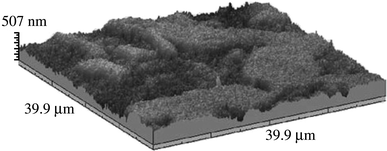
Surface topographies of 1040 steel substrates preheated at 723 K by a plasma jet in air (Ref 13)

These results show the difficulties of such analyses, which are very important for understanding variations in coating adhesion.
Physical Aspect of Substrate Surfaces
Substrate Surface Topography
Several authors have pointed out that mean surface roughness R a of metals or alloys (except Au and Pt) increases with substrate preheating. Fukumoto et al. (Ref 24) have noted that, when a surface was polished to a particular average roughness R a, coating adhesion was not as strong as it was when the same roughness was produced by preheating. To more accurately characterize the substrate surface, they (Ref 24) used another index of surface topology: skewness (S K ) which increases from negative values to positive ones upon preheating a polished surface and splat shapes changes correspondingly from fingered to disk shaped. The surface skewness is defined by:
where z is the surface height, m its mean value, φ(z) the distribution function of surface height, and \( R_{\Updelta q} \) the root mean square roughness. Cedelle et al. (Ref 25) have shown that changes in surface topography in the nanometer range of a 304L stainless steel substrate have a large effect on the wetting behavior of molten metal droplets placed on the surface. The contact angle is maximum when surface skewness is zero and decreases for larger values of S K , both negative and positive. Hence substrate preheating does not modify just the chemical composition and thickness of the oxide layer on the metallic substrate, but also its physical aspect, which plays a key role in the behavior of impacting particles. For S K > 0 (more peaks than undercuts) obtained for stainless steel 304L preheated at 673 K by a d.c. plasma jet (Ref 24-26) or a laser (with a power density over 50 MW/m2) (Ref 20), the resulting zirconia splats were disk shaped. For example, Fig. 5 represents the surface topography of 304L stainless steel after polishing at room temperature and preheated at 673 K. The preheated surface with S K ~ 1 presents more peaks than valleys compared to the not-preheated, polished substrate where S K ~ 0.

304L stainless steel substrate surface (1 × 1 μm2) topography. (a) As polished and (b) plasma jet preheated at 673 K (Ref 25)
When the substrate surface is treated with a laser, average roughness R a and skewness S K vary with energy density and number of pulses as indicated in Table 2.
Adsorbates and Condensates
A careful study of adsorbates and condensates at the substrate surface has been done by Li and Li (Ref 8). Often, water is the main component at the surface. Its adsorption on an oxide surface is usually the result of one of three possible mechanisms, or combinations of them, depending on the temperature of the measurement, intrinsic reactivity of the surface, and the number of defect sites at the surface (Ref 27):
-
1.
physisorption of molecular water
-
2.
chemisorptions of molecular water
-
3.
chemisorptions of molecular water followed by dissociation.
Physisorption corresponds to very weak interaction between the substrate and adsorbates, while chemisorption is much stronger and may involve partial charge transfer, which more readily leads to dissociation (Ref 27). Stronger adsorption occurs at steps and defects and new OHy radicals, resulting from dissociation, bond with a surface metal ion.
When the surface is heated adsorbed water species will be desorbed. This desorbtion of the water adsorbates is linked to adsorption features, desorbtion products, surface structural features, and types of surface materials. Physisorbed molecular water is generally completely removed by preheating up to 150 °C. However, with chemisorbed water, the thermal desorbtion temperature depends on adsorbed features and the subsequent desorbed product. For most oxide-covered metal surface, it occurs at temperatures ranging from about 127 to 320 °C as summarized in the table given in (Ref 8) for several oxides and nominal metal surfaces. The authors (Ref 8) underline that this desorbtion temperature range is in good agreement with the substrate preheating temperatures reported as transition temperature up to now. Therefore, they have studied the effect on splat formation of adsorbing and desorbing organic compounds on a stainless steel surface. They brushed xylene, glycol, and glycerol (Ref 8) on stainless steel substrates and shown that when the preheating temperature exceeded the boiling point of these liquids by 50 °C, impacting thermal spray particles formed regular disk splats.
Instead of the substrate temperature change, the effect of desorbtion of adsorbates and condensates on the particle flattening behavior was systematically investigated by Fukumoto et al. (Ref 28) in soft vacuum plasma spraying by reducing the chamber pressure and keeping the substrate at room temperature. Indirect measurements (determination of the pressure below which splats become disk shaped on different materials) have shown that desorbtion probably occurs at pressures between 92 and 26 kPa, depending on substrate material.
Measurements
Difficulties in Measuring Liquid Particles at Impact
Micrometer-Sized Droplets
There are two major difficulties in studying splat formation under thermal spray conditions:
-
1.
Time: in most cases of plasma and HVOF spraying particle flattening takes a few microseconds and solidification often starts before flattening is completed.
-
2.
Dimensions: a typical particle 30 μm in diameter produces, after flattening, a splat whose diameter is between 60 and 120 μm with thickness of at most a few μm.
Fast two-color pyrometers (50 ns) are now used to measure particle temperature during impact. Signals obtained at two wavelengths, in the range 600-800 nm, allow temperature evolution to be calculated. Temperature measurements of YSZ particles are complicated by the fact that molten zirconia is partially transparent to visible light; emitted radiation is not only from the surface, but also from some depth within, which adds to measurement errors. When considering the thermal radiation at one wavelength, the splat diameter evolution and its cooling rate can be determined. However, to correctly interpret the thermal signal, pictures of the flattening droplet should be taken at different times during flattening. It means that fast cameras should be used with long distance microscopes to see the details of such small objects. As the depth of field is severely limited (about 10 μm) flat and smooth substrates must be considered (R a of 1 μm corresponds to peaks in the 7-8 μm range). Ideally, to capture the entire impact process, images should be taken with intervals of a few tenths of microseconds between them, which is difficult when the fastest video cameras currently available allow recording of 100 consecutive images at 1 million frames per second with exposure times of 500 ns (Ref 29).
Millimeter-Sized Drops
Millimeter-sized drops are easier to observe during impact since flattening times are in the millisecond range and fast cameras up to 10,000 frames/s can be used to follow the particle flattening. However, while metal or alloy drops are relatively easy to produce using a furnace, ceramic materials are much more difficult to melt.
Study of Micrometer Droplets
Developments in Pyrometry Measurements
All studies before 2004 related to splat cooling were performed with the impact of d.c. plasma-sprayed particles. In 2005, such measurements were developed for RF torches with zirconia particles impacting on glass substrates (Ref 30). The substrate was heated by radiation, and particle velocity and temperature were measured prior to its impact, utilizing the method of Sakuta and Boulos (Ref 31) and the temperature of the flattening particle was recorded with a two-color pyrometer.
Impact Splashing Visualization
Immediately after impact, as discussed by Armster et al. (Ref 32), the compression wave emanating from the point of impact creates an instability along the contact line between the droplet, substrate and surrounding atmosphere, rupturing the fluid so that tiny droplets are ejected to heights of a few millimeters above the substrate. Escure et al. (Ref 33) observed these under spray conditions and their formation was correlated with the Sommerfeld parameter K, which characterize fluid flow. This choice is valid because in the first hundreds of nanoseconds following impact no solidification occurs. Using the set-up already described in the review of 2004, Cedelle et al. (Ref 34) with the camera parallel to the substrate surface have taken at impact photographs with a multiple exposure operation (10 shots, exposure: 5 μs, delay 5 μs) as shown in Fig. 6.

Multiple exposure photograph to show material ejection during the impact of a zirconia particle (~30 μm) impacting a preheated stainless steel 304L substrate at 200 m/s (Ref 34)
It appears that the ejected droplets (probably below 1 μm in diameter) have velocities in the range 15-20 m/s, which is about an order of magnitude less than the impact velocity. The ejection angle is between 30 and 60° relative to the substrate plane. These ejections are observed, provided K > 30, irrespective of the substrate temperature, which was varied from room temperature to 0.7 times its melting temperature (Ref 35).
Flattening Visualization
To capture particle flattening, it is first necessary to trigger the camera at the instant of impact, which is rather difficult. Second, only a few particles can be allowed to land in the area under observations (under conventional spray conditions about 108 particles/s can impact near the same location). Thus, all measurements require: a low powder flow rate (below 100 g/h); small orifices to direct particles along a well-defined trajectory; and either a water cooled aperture which is opened for a few tenths of seconds or fast scanning by the torch (moving it at 1 m/s). The advantage of using an aperture is that particles with known mean trajectory are collected, while their mean trajectory is unknown when the torch is moved rapidly.
Using a Fast Camera
Shinoda et al. (Ref 29) have used a high-speed video (HSV) camera (a prototype of HPV-1 of Shimadzu Corp. Japan) capable of recording 1 million frames per second with the set-up shown in Fig. 7. Beneath the second orifice, 500 μm in diameter (3 in Fig. 7) an optical detector generates a signal when a particle passes through it. A second detector is focused onto the substrate (6 in Fig. 7). The temperature evolution of the flattening particle is followed with the two-color pyrometer (11 in Fig. 7) while particle impact images are recorded with the HSV camera. The camera is triggered with the detector (5 in Fig. 7). A typical pyrometer signal, and its coordination with the camera triggering and recording is shown in Fig. 8.

Schematic diagram of the in situ monitoring system for capturing droplet impact under plasma spray conditions: (1) d.c. plasma torch, (2) V-shape first shield, (3) boron nitride plate with second orifice, (4) substrate and its holder with K-type thermocouple, (5) in-flight detector, (6) lenses, (7) digital oscilloscope, (8) high-speed video camera, (9) long distance microscope, and (10) digital time delay generator (Ref 29)

Thermal radiation history at 1000 nm wavelength recorded during the droplet impingement. Hatched regions correspond to the exposure period of the HSV camera (Ref 29)
High-speed video images were taken with yttria-stabilized zirconia droplets plasma sprayed onto a cold glass plate substrate, where flattening times are relatively long (~5-8 μs) when the substrate is heated flattening times are reduced (~2-3 μs) and multiple images of droplet impact cannot be recorded.
Photographing Impact
Mehdizadeh et al. (Ref 36) have developed a set-up to photograph one particle during its flattening in a given time range. Thus varying the time range for different particles, assumed identical at impact (same diameter, temperature, and velocity) it becomes possible to obtain photographs of the flattening at different times. Figure 9 shows a schematic of the experimental apparatus used.

Schematic of the experimental set-up to photography particle impacting on a glass substrate (Ref 36)
The number of impacting droplets is limited by a V shield followed by two diaphragms with orifices in them. Behind the last orifice is a detector to discern the passage of an in-flight particle. This signal is used to trigger the flash lamp of the Nd: YAG laser, a process that requires a minimum of 150 μs before triggering the Q switch. Thus, the last diaphragm must be far enough from the substrate to leave the particle enough time before landing, according to its velocity. During particle impact on the substrate the pyrometer (previously described in the review of Fauchais et al., Ref 10) measures particle temperature, both in-flight and while flattening. The image of the flattening droplet is taken with a CCD camera coupled to a long range microscope. The CCD camera is operated at 30 frames/s, each frame having an exposure of 33 ms. The laser pulses (20 MJ power and 5 ± 2 ns duration emitted by the Nd:YAG laser) allows getting an image of the flattening particle at a given time: the 5 ns of the laser flash are short enough, compared to the few microseconds of the flattening time, to freeze all motion in the image. The laser flash is triggered by the pyrometer signal level. By varying the time delay, different stages of droplet impact are observed. The contrast is maximized by illuminating particles from the front and photographing them from behind through the glass substrate. Thus, spreading droplets are silhouetted against a bright background. This set-up was also used to study the impact of metal particles (Ref 37).
Later the system was extended to photograph particles flattening on a metal substrate (Ref 38). Figure 10 shows the set-up developed.

Schematic of the experimental set-up to photograph particles impacting on a metal substrate (Ref 38)
Compared to the previous set-up (Fig. 9) no laser flash was used and with the help of two mirrors the electronic shutter of the camera (12 bit CCD camera) was triggered to open by a signal from the D4 sensor, recording the signal from the in-flight particle behind the last diaphragm. The camera shutter was opened for about 500 μs with no added illumination. This produces single, integrated images of the splats at the maximum spread diameter, image which can be compared with the splats collected afterward. This system is similar to that used by Escure et al. (Ref 33) described in the review (Ref 10) and then optimized by Cedelle (Ref 34). The set-up of Fig. 10 has been used by Mc Donald et al. (Ref 26) to study the effect of substrate oxidation on the flattening of plasma-sprayed nickel particles.
Thermal Contact Resistance Determination
Bianchi et al. (Ref 39) adjusted the thermal contact resistance values in a numerical model so as to match the experimental cooling rate of zirconia (similar to that presented in Fig. 8) with that of the numerical simulation. More recently, an analytical, one-dimensional (1D) heat conduction model was developed to determine the thermal contact resistance, in which the liquid splat at its maximum extent was assumed to be a disk transferring heat to the substrate (Ref 40). Charts were presented showing variation of the nondimensional cooling rate with inverse Biot number. As previously shown by Bianchi et al. (Ref 39) thermal contact resistance between heated surfaces and splats was more than an order of magnitude smaller than that between unheated surface and splats. However, such measurements only give a mean value of a parameter characterizing the heat transfer splat-substrate. The thermal contact resistance probably varies with pressure during flattening, as demonstrated by Cedelle et al. (Ref 35) when considering copper millimeter-sized droplets impacting on a 304L stainless steel substrate.
Study of Millimeter-Sized Particles
Fauchais et al. (Ref 10) described the experimental set-ups used to observe impact of millimeter-sized droplets; the only new one, since that review, was presented by Cedelle et al. (Ref 25). It consists of an inductively coupled RF argon plasma used to melt the tip of either metal or ceramic rods to produce millimeter-sized drops (see Fig. 11).

Free-falling millimeter-sized drop set-up comprising RF argon plasma at atmospheric pressure to melt the tip of metal or ceramic rods, a two-color pyrometer and a thermocouple at the substrate surface (Ref 25)
The surface temperature of the flattening drop is followed by a fast (50 ns) two-color pyrometer and the temperature of the substrate surface is measured with a thermocouple according to the method of Heichal and Chandra (Ref 41). The thermocouple system consists, as shown in Fig. 12, of two thermoelectric wires connected by a graphite film, providing an electrical contact between the constantan wire and the metallic substrates. The response time of the thermocouple is in the microsecond range and it is calibrated in a furnace. The voltage generated by the thermocouple is recorded with a data acquisition card and analyzed in a computer.

Substrate surface temperature measurement set-up for the impact of millimeter-sized drops (Ref 25)
This set-up, assuming that the flattening particle temperature is uniform, allows calculating the evolution of the thermal contact resistance between the flattening particle and substrate provided that the variation of contact area with time is known. This can be measured by recording droplet flattening with a fast camera (5000 frames/s), if we assume that contact is uniform everywhere under the splat.
Experimental Results About Splat Formation
Studies of splats have been done mainly on flat and smooth (R a < 0.05 μm for polished metals or alloys and R a < 0.2 for ceramics) substrates. Spraying was usually performed in an air atmosphere with, in most cases, impacts normal to the substrate. Most of the following discussion will focus on these results, and our present knowledge of impact on rough substrates will be presented only briefly in the last section.
General Remarks
It must be emphasized that all results presented below are related to particles fully molten at impact (Ref 42), which is generally true for plasma (Ref 38) or wire arc (Ref 43) sprays, but not always for HVOF sprays, where the tendency is to develop experimental set-ups where the particles achieve larger velocities but temperatures below the melting point (Ref 44). During the impact of unmelted particles, as occurs in Cold Spray, HVAF or high power HVOF spraying, the phenomena controlling particle flattening (Ref 45, 46) are quite different from those discussed here.
No discussion will be devoted to impact splashing occurring during the first few hundreds of nanoseconds following impact. This splashing depends on the Sommerfeld number (K) at impact (Ref 25, 33, 35) and results in the ejection of tiny (some tenths of micrometers) droplets which rise a few millimeters above the substrate, outside the dynamic boundary layer, and are mostly entrained into the plasma flow.
The physical parameters that influence the spreading of a droplet hitting a solid surface include: initial droplet diameter d, impact velocity v d, liquid mass density ρ, liquid viscosity μ, liquid-gas surface tension σ, and liquid-solid contact angle θ. Combining these into nondimensional groups reduces yields three variables: contact angle (θ), Reynolds number (Re), and Weber numbers (We), defined as:
Re is a measure of the droplet inertia to viscous force and We is a measure of inertia to the surface tension force. Typical values at impact during plasma spraying for both Re and We are between 104 and 105. The Reynolds number depends indirectly on droplet temperature since droplet viscosity is sensitive to temperature.
The earliest attempts to derive an analytical expressions for the extent of maximum splat spread (D) was by Madejski (Ref 47) and Jones (Ref 48); several other models (Ref 49) have been proposed since. All follow a similar energy conservation approach, equating the surface and kinetic energy of the droplet before impact, to the surface energy after impact, while deducting the energy dissipated during impact due to work done in deforming the droplet against viscosity. Droplet impact models predict the spread factor after impact (ξ = D/d, also known as the flattening ratio), which is in general a function of We, Re, and θ. Under typical thermal spray conditions, surface energy is negligible in comparison to kinetic energy, and the spread factor becomes a function of Re alone, and
where a and b are constants, with a varying from 0.5 to 1.2941 and b typically 0.125 to 0.25. Analytical and numerical investigations by different groups are summarized in the papers of Kang and Ng (Ref 49) and Vardelle et al. (Ref 50). Works in this field have also been performed by Amada et al. (Ref 51, 52) and Liao et al. (Ref 53).
If the droplet is freezing as it spreads, the maximum spread diameter may be reduced. The effect of solidification in restricting droplet spread is modeled by assuming that all the kinetic energy stored in the solidified layer is lost. If s* is the dimensionless solid layer thickness when the droplet has spread to its maximum extent (s* = s/d, where s is the solid layer thickness) the maximum spread factor is (Ref 54):
The growth in thickness of the solidified layer can be calculated using an approximate analytical solution that assumes that heat transfer is by 1D conduction and the substrate is semi-infinite in extent. With these assumptions the dimensionless solidification thickness can be expressed as a function of the Stefan number (Ste = c(T m − T s,i)/H f), Peclet number (Pe = v d d/α), the thermal properties of the substrate and droplet, and the thermal contact resistance between the droplet and substrate (Ref 54).
The larger the spread factor (ξ), the thinner is the resulting splat. As freezing time varies roughly with the reverse of the square of the thickness (Ref 10), thinner splats start solidifying before thicker ones, assuming thermal contact resistance is the same. ξ increases when the particle impact velocity and/or temperatures are larger.
Particle oxidation in-flight can modify particle behavior at impact. For fully molten particles at impact, Sobolev and Guilemany (Ref 55) have listed phenomena that likely influence upon flattening and solidification:
-
Flattening of oxidized droplets impinging onto the substrate surface is similar to that of composite powder particles except that, due to splat oxidation, the volume fraction of oxides varies with time.
-
Oxides developed during particle flight play an important role in droplet flattening and splat-substrate interaction. Oxidation also occurs at the upper liquid surface of the solidifying splat.
-
Oxidation decreases the pressure developed during droplet impact which is detrimental to obtaining good contact between the substrate and splat.
-
A decrease in the liquid-solid contact angle, which improves wetting of the substrate by the splat, leads to a decrease in splat thickness and an increase in splat radius that reinforces splat-substrate adhesive bonding. Influence of wetting on the flattening process decreases with an increase in the velocity of the droplet impingement onto the substrate surface and a decrease in the substrate initial temperature.
Deshpande et al. (Ref 56) have also studied the effect of in-flight oxidation of Ni-5Al coatings sprayed by different techniques and proposed schematic models for describing the various probable mechanisms occurring. They showed that in-flight oxidation can lead to an oxide shell at the periphery of the particle, which splashes upon impact and results in a coating microstructure with distributed chunks of oxide and splats separated by oxide bands. It is thus very important to control in-flight oxidation, for example by using gas shrouds (Ref 13, 57). Of course, the best solution is to spray in a controlled atmosphere.
In spite of the large number of parameters discussed in the studies reviewed above, several important variables have not been considered, including substrate oxide layer thickness, composition, roughness, and degree of particle oxidation (both surface and internal).
Examples of New Results Obtained at Impact
-
1.
Photographs of molybdenum (Ref 37) and zirconia (Ref 40) particles plasma sprayed on cold glass substrates, taken with the set-up shown in Fig. 9, have shown very interesting behavior. Splats spread to their maximum extent within 1-2 μs after impact, forming a thin sheet with a diameter up to 10 times that of the initial droplet and a thickness of only about 0.5 μm. The liquid sheet then began to rupture, initially around the solidified central core and later at other sites. At the end the splats disintegrated almost completely and only a central solidified core remained on the surface.
-
2.
On glass substrates preheated over the transition temperature, molybdenum (Ref 37) and zirconia (Ref 40) particles were photographed as they formed disk-shaped splats. The maximum splat diameter was only about one-third of that obtained on a cold glass substrate. On stainless steel preheated slightly over the transition temperature, the maximum diameter of splats photographed by a camera with long exposure time (a few tens of microseconds) was close to that of splats collected Cedelle et al. (Ref 25). Similar results were obtained for nickel (Ref 26) or amorphous steel (Ref 37) particles sprayed on stainless steel.
-
3.
Millimeter-sized tin particles impacting on cold stainless steel substrates (Ref 42) disintegrated upon impact in a cloud of tiny particles shed from their edges. A similar result (extensively fingered splats) was obtained when spraying by wire arc aluminum particles (micrometer-sized) on cold stainless steel (Ref 43). Pictures taken during the flattening of millimeter-sized drops of copper or nickel on cold stainless steel showed the development of fingers (Ref 35).
-
4.
When the stainless steel substrate is preheated to 200 °C, the solidification of low melting temperature millimeter-sized drops is delayed: tin (Ref 42), aluminum (Ref 43), nickel, and copper (Ref 25) droplets form disk-shaped splats.
-
5.
The velocity at which flattening occurs has been measured for millimeter- and micrometer-sized metallic and ceramic particles. With plasma preheating, the flattening time of micrometer-sized zirconia droplet on stainless steel was between 1 and 2 μs against 2 to 5 μs for a cold substrate (Ref 25). The spread times for molybdenum and amorphous steel particles on hot glass were about half those obtained on cold glass (Ref 37). Similar results were obtained with millimeter-sized drops of Ni and Cu impacting on a stainless steel substrate where the flattening time was between 1 and 2 ms on the preheated 304L against 3-5 ms on the cold one (Ref 25).
-
6.
In all cases, the cooling rates of particles sprayed onto substrates preheated over the transition temperature is always higher (sometimes more than one order of magnitude) than that obtained on cold substrates.
Transition Temperatures, Pressures, and Laser Treatment
Transition Temperature
Several previous studies (Ref 10, 28, 58) have pointed out that, of all the different particle/substrate interface parameters, substrate temperature, and ambient pressure most significantly affect the flattening behavior of sprayed particles. Experiments have shown that when the substrate temperature is increased, the splat shapes of most materials sprayed onto flat substrates undergoes a transition from a distorted shape with splashes to a disk shape. This change occurs over a narrow temperature range, and Fukumoto et al. (Ref 59) have defined the transition temperature, T t, as a critical substrate temperature over which more than 50% of splats are disk shaped. Figure 13 shows how the fraction of disk splats varies with substrate temperature for Ni particles sprayed on a AISI304 stainless steel substrate, and how the transition temperature is defined.

Dependence of fraction of disk splat and coating adhesion strength on substrate temperature: Ni particles on AISI304 stainless steel (Ref 28)
Fukumoto et al. (Ref 28) present transition temperatures for various metals (Ni, Mo, Cu, Cr, Cu-Zn) and oxides (Al2O3, TiO2, and YSZ) on AISI304 stainless steel between 318 and 610 K. These temperatures are much less than particle and substrate melting temperatures. Similar results have been obtained for different sprayed materials (cast iron, low carbon iron, amorphous steel, nickel, nickel-based alloys (Ni-Cr, Ni-Al), aluminum, tin, copper, lead, molybdenum, titanium alloy (TA6V), alumina, titania, alumina-titania, and YSZ hydroxyapatite) and substrates (AISI304 stainless steel, gold, Al-Si-Cu, 1040 low carbon steel, copper, titanium alloy (TA6V), inconel, glass, YSZ) (Ref 4, 5, 13, 25, 26, 28, 30, 37, 40, 43, 52, 56, 60-66).
In most studies, splat morphologies were determined after their formation, though fast pyrometry was used in some experiments. The interpretation of the time evolution of the pyrometer signal, especially during the flattening phase, was far from straightforward (see the review, Ref 10) without photographing the particle at different times, as is now possible (Ref 37, 38). Even if pictures are recorded at different times for different particles, while the pyrometer signal is obtained for the same particle (see “Photographing Impact” section), the trends observed allow interpretation of the pyrometer signals. Pyrometry, combined with photography, has shown that on cold substrates, below the transition temperature, Mo, Ni, YSZ, and amorphous steel particles sprayed on glass and stainless steel substrates spread to maximum diameters that were much larger than those obtained on preheated surfaces maintained over the transition temperature (Ref 26, 37, 38). Then, the liquid film breaks up, finally leaving a central solidified core and splashes at the periphery. However in other cases, below the transition temperature, the splat is extensively fingered, but, without photos taken at different times, the way these fingers were produced is difficult to determine.
Cooling rates on surfaces kept at temperatures over T t are much larger than those measured (Ref 10, 25, 26, 37, 38) on substrates maintained below T t, which indicates better splat-substrate contact. This is confirmed by examining the bottom surface of splats, as Fukumoto was the first to do (see Ref 28, 60) and the review, Ref 10). With preheating over T t, the bottom surface of the splat in good contact with substrate is by far larger than the one obtained when preheating below T t.
Even when a substrate is maintained above T t, splashing may be observed if Reynolds and Weber numbers are sufficiently high. For example, Li et al. (Ref 18) have shown that even when the stainless steel substrate was preheated over the transition temperature, splashing of Cu particles was observed for Re > 50,000.
Some studies have demonstrated the importance, when preheating, of controlling heating rate, time and temperature to obtain oxide layers on metal surfaces with a well-defined composition, thickness, and roughness. For example McDonald et al. (Ref 26) showed that when stainless steel is preheated to 650 °C splat splashing is promoted, while when it is only preheated to 350 °C disk-shaped splats are collected. Their measurements showed that the surface morphology obtained at 650 °C is quite different from that at 350 °C and measurements of Haure (Ref 11) show that the oxide composition at 650 °C is hematite and a nickel spinel.
Laser Treatment
As described in “Effect of Preheating Conditions (iii)” section, depending on the energy density, laser treatment first removes adsorbates and condensates and, if energy density is increased further, rapid melting and cooling of the surface may occur with corresponding oxidation (Ref 17) and roughness (R a, S K ) modifications (Ref 20). Li et al. (Ref 17) studied laser cleaning (PROTAL process) of polluted surfaces by plasma spraying Ni-Al particles onto TA6V mirror polished surfaces on which oil and carbon particles had been applied. As expected, no adhesion occurred if the substrate was dirty. The PROTAL process allowed cleaning of the pollutants and resulted in acceptable bond strength when laser parameters were set to remove surface contaminations. Tensile strengths obtained by this on-line laser treatment reached almost 80% of those obtained by traditional grit blasting. With no surface pollution (except that from the atmosphere) and larger energy density, which modified the substrate skewness (S K > 0), splats were disk shaped (Cu on 304L stainless steel, Ref 20 and Ni-Al on TA6V, Ref 17).
Transition Pressure
Fukumoto et al. (Ref 28) systematically investigated the effect of desorbtion of adsorbates on particle flattening behavior in low-pressure plasma spraying by reducing the ambient pressure, the substrate temperature being kept at room temperature (so that there was no modification of native oxide at the surface). Splat morphologies of metallic particles (Ni, Al, Ti, Cu, Ni-Al, NiCrAlY) sprayed onto stainless steel substrates, obtained below a critical pressure called the transition pressure, P t, were typical of those usually seen on substrates preheated over T t, P t was defined as the pressure below which the fraction of disk splat exceeded 50%. The reduction in ambient pressure diminished the vapor pressure of the adsorbates and probably accelerated vaporization/desorbtion of adsorbates from the surface. The transition pressure distribution for each sprayed material is summarized in Fig. 14. Fukumoto et al. (Ref 28) note that ordering of substrate materials corresponds well to their placement in the periodic table, that is, Ti, Cr, Ni, and Cu. Future research will clarify this material order.

Transition in thermal-sprayed particle with both substrate temperature and ambient pressure (Ref 28)
The dependence of the transition temperature on the sprayed material is also shown in Fig. 14, for comparison. The dependence of T t and P t on the particle material is quite similar, indicating that T t and P t have an equivalent effect for desorbtion of adsorbates. Fukumoto et al. (Ref 28) observed that the microstructure of the bottom splat surface change in much the same way when either pressure is reduced or the substrate is heated.
Morks et al. (Ref 67) have studied the effect of chamber pressure on the microstructure of cast iron splats, including oxides and graphite. The microstructure of cast iron splats greatly depends on spray parameters such as substrate temperature, chamber pressure, and spray distance. At low chamber pressures (below 20 kPa), most splats exhibit a disk shape with high flattening ratios, whereas star-shaped splats appear when increasing the chamber pressure. Spraying at high chamber pressures (between 40 and 100 kPa) causes the formation of pores and thick oxide zones at the splat/substrate interface, mainly due to atmospheric gases, which are responsible for a decrease in splat adhesion. Spraying in an argon atmosphere reduces splat oxidation due to a decrease in oxygen partial pressure and also increases the quantity of disk-shaped splats at pressures larger than that corresponding to P t in air.
Three-Dimensional Transition Curve in Thermal Spray Process
The dependence of the fraction of disk-shaped splats both on the substrate temperature and ambient pressure is summarized schematically (Ref 28) in Fig. 15, as a 3D transition curve. Selecting the optimum operating conditions in the combination of both factors in the thermal spray process should allow controlling the coating microstructure, and thus, any other properties, such as porosity, density, thermal conductivity, of the coating. Fukumoto et al. (Ref 28) present 3D transition curves, based on experimental data, for several different powder materials.

Three-dimensional transition map of flattening behavior in the thermal spray process (Ref 28)
Effect of Transition Temperatures and Pressures
General Remarks
Single particle flattening is very complex because fluid flow and solidification must be considered simultaneously: solidification starts before flattening is completed and can induce splashing. Before discussing the different phenomena that may influence transition temperature and pressure, the main parameters controlling flattening and solidification will be reviewed (Ref 10):
-
The impact pressure can be very high (few thousands of MPa): larger than the classic water hammer pressure ρp · c l · v d, where c l is the sound velocity in the liquid phase, ρp the mass density of the impacting droplet, and v d the droplet velocity at impact. The high pressure region extends over a radius r m much smaller than the final splat radius. The contact pressure spreads out and dissipates quickly with droplet flattening. At the periphery, the impact pressure may not be enough to overcome the capillary pressure required to force liquid into the crevices between asperities on the surface and contact between the flattening particle and the substrate can become very poor in this zone. Around the impact point, over an area of radius r m, the impact pressure will always be enough to force liquid into surface crevices and thus the adhesion in this zone will be good.
-
When a molten droplet contacts a rough, solid surface, air is trapped in crevices at the liquid-solid interface, creating a temperature difference between the molten metal and the substrate, whose value depends on surface finish, contact pressure, and material properties. To quantify the magnitude of this effect, the thermal contact resistance (R c) is defined as the temperature difference between the droplet (T d) and substrate (T s) divided by the heat flux (q″) between the two.
$$ R_{\text{c}} = \frac{{T_{\text{d}} - T_{\text{s}} }}{{q^{\prime\prime}}} $$
Although in general R c can vary with both time and location, it is usually assumed to be constant for simplicity. Thermal contact resistance values have been measured directly under millimeter-sized droplets of molten metal impacting on flat surfaces by measuring either the splat surface temperature variation using an optical pyrometer (Ref 35), or transient substrate temperature with thermocouples (Ref 41). Contact resistance was determined by selecting values that gave best agreement between predictions from numerical or analytical models and experimentally measured temperature variations.
McDonald et al. (Ref 40) plasma-sprayed molybdenum and yttria-stabilized zirconia particles onto glass and Inconel 625 substrates held at either room temperature or 400 °C. Samples of Inconel 625 were also preheated for 3 h, and then air-cooled to room temperature before spraying. A rapid two-color pyrometer was used to collect thermal radiation from the particles during flight and spreading and determine the cooling rate of spreading particles. An analytical heat conduction model was developed to calculate the thermal contact resistance at the interface of the plasma-sprayed particles and the substrates. The analysis showed that thermal contact resistance between the heated or preheated surfaces and the splats was more than an order of magnitude smaller than that on nonheated surfaces held at room temperature. As seen in Table 3, particles impacting on the heated or preheated surfaces had cooling rates that were significantly larger than those on surfaces held at room temperature, which was attributed to smaller thermal contact resistance.
-
Due to the very high cooling rates during particle flattening (more than 108 K/s at the very beginning of the cooling process when contact between the droplet and substrate is good), the droplet undergoes hypercooling, generally resulting in heterogeneous nucleation starting at contact with the underlying material.
Fukumoto et al. (Ref 28) have raised the question ‘‘why and how the splashing occurs on the cold substrate surface?” Possible reasons that have been proposed include rapid solidification at the bottom surface of the splat, the presence of adsorbates and condensates on the substrate surface and poor substrate surface wettability.
Desorbtion of Adsorbates and Condensates
When a hot particle lands on a cold surface, adsorbates and condensates vaporize rapidly, creating high pressure under the spreading liquid and preventing good contact, except in the area at the center of the particle, where the impact pressure is very high. Thus, the liquid spreads to its maximum extent (see “Examples of New Results Obtained at Impact” section), forming a very thin lamella. Then, the liquid portion of the flattened droplet begins to disintegrate, initially from the solidified central core and later, from sites within the liquid film sometimes small holes are observed even in the central part of the splat, where contact between the splat and substrate is good, which are caused by vaporized adsorbates bursting through the liquid and escaping (Ref 4, 60, 62, 67, 68).
To ensure that the pretreatment used to remove adsorbates from the substrate surface does not modify it (by changing in oxide layer thickness, composition, or roughness) one can either lower the pressure, or clean the surface with a laser set at an energy density level low enough to not that affect the oxide layer, or by preheating a surface if it cannot be oxidized (when it is made of gold or platinum or oxide).
-
1.
The transition pressure, as studied by Fukumoto et al. (Ref 28), is characteristic of the surface: no chemical modification of the surface occurs when pressure is lowered, and desorbtion is the only possible physical change taking place. However, transition pressures for different materials do not follow the same classification as that obtained for transition temperatures (compare Fig. 14 and the table presented in Ref 8). The differences are probably linked to the native oxide layers of the different substrates, which also depend on surface preparation.
-
2.
When preheating gold substrates (Ref 58) or YSZ substrates (Ref 25) beyond the transition temperatures (723 and 553 K, respectively) or over, reaching temperatures as high as half the melting point, splats were disk shaped. Preheating a gold surface increased its R a, but did not affect the roughness of YSZ substrate; in both cases, the S K value did not change and remained negative. To ascertain the influence of substrate roughness on splat shape an AISI304 stainless steel that had been polished (producing S K < 0) was heated to 673 K (changing S K = 0.895) and then gold coated (Ref 20). Splashing occurred on both heated and nonheated surfaces, demonstrating that in this case the S K modification is not the dominant factor.
McDonald et al. (Ref 40) have studied the impact of Mo or YSZ droplets upon preheated glass substrates at 673 K. Preheating gave splats that had larger cooling rates, smaller maximum spread diameters, with significantly reduced fragmentation and about one order of magnitude smaller contact resistance compared to droplets impacting cold glass surfaces. Here again the only modification is the desorbtion of adsorbates.
Fukumoto et al. (Ref 58) measured the fraction disk splats obtained when copper was sprayed on AISI 304 stainless steel substrate once preheated to 723 K (S K = 1.93) and then kept in an air atmosphere at room temperature for 24, 48, 72, 96, and 120 h, respectively. The result is shown in Fig. 16. Twenty-fours after heating, a high fraction of disk splats was obtained. After 50 h or more the fraction of disk splats began to decrease. Finally, the fraction of disk splats decreased to <50% over 72 h and more. As expected, R a and S K did not change, regardless of the elapsed time. However, Cedelle et al. (Ref 25) have shown that on the same substrates, Ni and YSZ particles still produced disk-shaped splats after 1 h had elapsed between preheating and cooling and their cooling rate was reduced by about 40%.

Relationship between elapsed time after heating to 723 K and fraction of disk splat (Ref 58)
To check the effect of delaying solidification, alumina particles were sprayed on a polished alumina substrate preheated at 1800 K. Splats sprayed at 100 m/s with a mean temperature of 3000 K were almost disk shaped but their diameter was about twice that obtained when preheating the alumina substrate over the transition temperature (Ref 33). In this case, particle flattening is probably completed before solidification occurred, but unlike the case of a cold substrate, the contact between the liquid and substrate is good. However, when the impact velocity was increased up to 300 m/s the splat was fingered. This was probably due to solidification starting before flattening is completed.
-
3.
The laser treatment effect shows that, when laser energy density is limited to that necessary to just remove adsorbates and condensates on TA6V substrates, the copper splats are mostly disk shaped.
Substrate Surface Modifications
When metal surfaces are preheated over the transition temperature (Ref 4, 5, 10, 13, 25, 26, 30, 37, 38, 40, 43, 52, 56, 60-66) or treated with laser energy densities high enough to modify the oxide layer (Ref 17, 20, 58), the surface is changed. In addition to desorbtion of adsorbates, the oxide layer composition, thickness and roughness is modified. The net result is generally the formation of disk-shaped splats with higher cooling rates (or lower thermal contact resistance) and higher spreading velocity (better wetting of the substrate by the flattening droplet) than those collected on cold substrates (see “Examples of New Results Obtained at Impact” section). The question is, which of these parameters is most influential in determining splat shape?
The work of Cedelle et al. (Ref 25) has shown that having positive S K on a preheated AISI 304 substrate improves the static wetting of copper. When Ni and YSZ particles are sprayed on such a substrate their flattening time is reduced and their cooling rate is faster compared to a substrate that has not been preheated. Thus, S K modification, together with desorbtion of adsorbates, probably controls these phenomena. Such a conclusion is backed by the observations of Fukumoto et al. (Ref 58) on copper splats formed on AISI 304 substrates that had been laser treated with power densities varying from 0 to 90 MW/m2. The R a value remained almost unchanged, staying the same as that of the polished substrate surface at laser power densities up to 50 W/mm2. However, R a increases significantly when laser power density is raised above 50 W/mm2. S K also increases with laser power density over 50 W/mm2, and changes from negative to positive; the percentage of disk-shaped splats increased almost linearly with S K .
In spite of several experimental investigations, questions about splat formation remain, because most experimental results are incomplete: often the substrate oxide analysis is not given, or cooling rate and/or flattening velocity or time are missing and so on.
Another observation, which has to be explained, is that droplets splash on substrates preheated over T t when impact Reynolds number is very high. The resulting splats being thinner than those obtained with lower Re, such splashing may be explained by solidification starting around the periphery of the spreading droplet before flattening is complete, so that the outward flowing liquid jets over the top of the solid layer, becomes unstable and breaks-up. With lower impact velocities, the liquid will not have enough kinetic energy to jet over the solid barrier and will not splash.
Contact Between Splat and Substrate
Several questions must now be addressed: how does the splat adhere onto the substrate? How can there be continuity between materials (splat and oxide layer at substrate surface, for example) with different crystallographic structures? Does good wetting and high pressure allow liquid to filling all the crevices in the surface at the nanoscale, creating mechanical adhesion? Can diffusion occur in such short times (a few microseconds)? Is a chemical reaction possible between the impacting droplet and substrate? Unfortunately, only a very few answers exist and much more research is still necessary, requiring careful studies of interfaces.
Alumina particles were sprayed onto alumina polished (R a ≈ 0.4 μm) plasma-sprayed coatings (Ref 69). The latter were either as-sprayed (with more than 99 wt.% of γ phase) or preheated at 1373 K at a rate of 5 K/min, annealed for 6 h and cooled at a rate of 5 K/min resulting in a 100% α-columnar structure. Some were also preheated to 1873 K with a temperature ramp of 5 K/min, annealed for 3 h, and cooled at a rate of 5 K/min resulting in α-granular structure with grains between 3 and 5 μm. On the γ-alumina substrate alumina splats (γ phase) exhibited columnar and regular structure ~100-150 nm; the adhesion of the alumina coating (300 μm thick) obtained on this smooth substrate was 35 ± 3 MPa! On the columnar α-alumina substrate splats (γ phase) got columnar and irregular structure ~150-300 nm; the adhesion of the coating was only 3 ± 1 MPa. On the α-alumina substrate with a granular structure splats (γ phase) achieved a very irregular structure ~100-400 nm, and splats had the tendency to peel off so that it was impossible to achieve any coating.
It has been shown that the preoxidation of smooth (R a < 0.05 μm) low carbon steel substrates in a furnace under a CO2 rich atmosphere at atmospheric pressure allows the formation of a wüstite (Fe1−x O) layer which improves significantly the adhesion (>55 MPa) of alumina coatings in spite of the rather low roughness (0.10 μm < R a < 1.00 μm) of the oxidized surface (Ref 70). It appears that plasma preheating of steel samples did not modify the morphology of the preoxidized wüstite layer formed (R a ≈ 0.2 μm). In spite of maintaining the surface condition, part of the wüstite scale, very probably the most superficial one, is oxidized into magnetite (Ref 71). This has already been observed on wüstite and it corresponds to a topotactic phase transformation. This change of composition is liable to occur even inside a grain, so that it may have no harmful consequence on the cohesion of the iron oxide scale. The presence of metastable γ-Al2O3 together with α-Al2O3 was somewhat surprising, because the former phase is generally the only one observed under the spraying conditions used. It is possible that the γ alumina phase was localized in direct contact with magnetite, as far as they have the same crystallographic structure (spinel) with lattice parameters rather close to 0.793 nm for alumina instead of 0.839 nm for magnetite 0.834 nm for lacunars magnetite. If such an assumption could be verified, it could explain the good adherence of the coating. Indeed, in these conditions, a steel substrate and the wüstite phase, then between the latter and magnetite (topotactic transformation), and finally between the magnetite and γ alumina (epitaxial relationship). This might justify a physical adhesion, and perhaps also a chemical one if a chemical reaction occurs between both spinel phases, which in principle could form mixed oxides.
For example, with a polished Ti-6Al-4V substrate, the presence of alumina diffusing to the substrate surface upon preheating at 400 °C produces excellent adhesion (48 ± 12 MPa) of the sprayed alumina coating. This is probably due to the chemical continuity at the interface substrate-coating with the presence of alumina at the surface of Ti-6Al-4V substrate (Ref 5).
Plasma enhanced chemical vapor deposition (PECVD) has been used to deposit thin (2 μm) alumina coatings on Ti-6Al-4V substrates (Ref 11, 69, 72). Coatings were achieved by introducing a mixture of 6 vol.% TMA (tri-methyl-aluminum) in argon in the afterglow of an oxygen microwave discharge (P = 1600 W). When spraying alumina on the PECVD coated surface, preheated at 300 °C, splats exhibited porous morphology, as shown in Fig. 17. In spite of that, adhesion of the APS coating on a polished Ti-6Al-4V substrate covered by a 2-μm thick PECVD coating is excellent: more than 60 MPa. When decreasing the PECVD film thickness from 2 μm to 200 nm, a “normal” dense morphology was found. This effect can perhaps be linked to the thermal conductivity of the alumina film and the presence of gases coming from the PECVD process, which have not been completely eliminated upon preheating. They can induce out-gassing during the impact. The poor thermal conductivity of the alumina film decreases the rate of solidification and the splat remains liquid.

Two alumina splats collected on a 2-μm-thick alumina coating deposited by PECVD on Ti-6Al-4V mirror polished substrate: left splat where all material is concentrated in its rim, center splat with lace aspect (Ref 69)
The 20- to 30-nm thick TGO layer developed during preheating of hot stainless steel substrates is assumed to improve both the YSZ liquid wetting and the formation of chemical bonds between the splat and the substrate (Ref 5). The interface oxide layer is composed of elements from both the ceramic splat (Zr) and the substrate (Cr, Fe), as determined by EDS using a sufficiently small beam spot size. When thicker oxide layers are formed with preheating at higher temperatures, the adhesion diminishes. The oxide layer on the surface of a cold substrate is probably only a couple of atomic layers thick, and is therefore far less significant than that of the hot substrate.
Impact on Inclined Substrates
On stainless steel, copper and a few other polished substrates (R a < 0.1 μm) preheated over the transition temperature, when the spray angle increases from 0° to 75°, splats have an elliptical shape, the ratio of the major to the minor axes increasing when the spray angle increases (Ref 49, 67, 73-76). For different materials (alumina, zirconia, titania, Al, Ni, Astroloy, and Cu), the relationship between the major and minor axes shows a strong linearity over a wide range of splat sizes. This observation implies that the elongation factor (EF) does not depend on particle diameter and impact velocity but only on spray angle. The splat thickness increases slightly along the inclined surface and it becomes progressively thicker in the direction of the inclined surface when the spray angle increases. This probably explains why, when the spray angle exceeds a critical value that depends on the sprayed and substrate materials, splashing occurs in the inclination direction. On cold substrates splats are extensively fingered, especially in the substrate inclination direction.
Substrate Melting During Impact
Molybdenum particles impinging on stainless steel melt the substrate locally, because the effusivity of the particles is larger than that of substrate (Ref 68, 77). Melting occurs on both cold and hot substrates. The melted crater on the substrate surface alters the flow direction of the droplet fluid and tends to form a free liquid detaching from the substrate surface (see Fig. 18a). Splats have a central part surrounded by other fragments as shown in Fig. 19 for substrates heated to (a) 200 °C and (b) 400 °C. The pieces along the outer periphery are produced by jetting, while those close to the center result from cracking of the central part with the detached pieces floating on a pool of liquid stainless steel (see Fig. 18b).

(a) Schematic diagram of a Mo particle impacting on a stainless steel substrate with molten steel below it within the crater formed. (b) Pieces of Mo detached from the central part of the impacting particle floating on molten steel

Morphology of Mo splats deposited on the stainless steel surface preheated, at (a) 200 °C and (b) 400 °C, respectively (Ref 68)
When spraying cast iron particles onto an aluminum alloy substrate preheated at 473 K, the temperature at impact exceeds the melting point of the substrate material. It leads to partial surface melting upon impact (Ref 67), and mutual diffusion occurs at the interface, which promotes the thin oxide layer formation of FeAl2O4. The interface formation can be considered to be a kind of mechanical bond, which also improves the adhesion property of splats. This observation demonstrates the importance of the first deposited layer in the adhesion property of coatings.
Impact on Rough Substrates
Most phenomena occurring when particles impact on rough surfaces normal to their trajectory have been described in the review of Fauchais et al. (Ref 10):
-
Surface roughness promotes adhesion. As emphasized by Mehdizadeh et al. (Ref 78), a droplet mainly adheres to a rough substrate due to mechanical interlocking between the surface and the bottom of the splat.
-
The spreading of the droplet is limited by surface irregularities, resulting in smaller and thicker splats (slower cooling), as well as an important flattening splashing behavior and a poorer contact than on smooth substrates. It is also much more difficult to analyze the oxide layer thickness and composition formed at the rough substrate surface.
-
The roughness size must be adapted to the sprayed particle mean size.
-
Preheating the substrate over the transition temperature usually improves the coating adhesion by a factor between 2 and 4. The most probable reason is the desorbtion of adsorbates and condensates.
However, it must be underlined that in all these works substrate roughness was achieved by grit blasting and characterized only by the average value R a which gives no information about the spacing between peaks and valleys.
Shinoda et al. (Ref 79) conducted an experimental study in which the surface roughness was artificially created and could be well characterized. Micropatterns were fabricated on quartz glass substrates by photolithography followed by wet etching. Four micropatterns were used as substrates: (a) a line-and-space pattern (L/S), (b) a pillar pattern in a tetragonal array (grid), (c) a pole pattern in a triangular array representative of a convex pattern (obstacle), and (d) a dimple pattern in a triangular array representative of a concave pattern (dimple). While the characteristic depths/heights of these patterns, z, were kept at ~1 μm, the areas of concavity and convexity of each pattern were designed to be identical except for the grid pattern. The arithmetic mean roughness of these patterns hence corresponded to R a = 0.5 μm. The spacing of these patterns, x, was varied from 4 to 20 μm. The anisotropic deformation of molten alumina droplets (sieved through a 35- to 65-μm mesh), sprayed with hybrid plasma, was observed on these substrates preheated at 700 K. Splats elongated in the direction perpendicular to the lines on the L/S pattern, and the degree of elongation tended to increase with the increase in the normalized pattern spacing ranging from 0.1 to 0.3. In addition, air was entrapped in each splat off-center by 1.5 times the radius of the droplet, regardless of the type, size, and pattern layout. This indicates that the air entrapment in the outer region of a splat on a rough substrate is inevitable under plasma spray conditions. Droplet spread, as already indicated in the review (Ref 10), can be affected by a roughness as small as R a = 0.5 μm, indicating the importance of controlling the surface roughness of a substrate on the micrometer scale in plasma spraying. These interesting findings led the authors to make the following recommendations:
-
The size of the surface pattern with a normalized pattern spacing of less than 0.1 would be a favorable pattern for preventing the fingering of splats.
-
Second, convex patterns such as the grid pattern should be preferred to concave patterns.
-
Last, the heights of obstacles also influence the fingering of splats. In the case of grid pattern, the heights of pillars less than half the splat thickness will be best to reduce fingering. The critical height of the obstacle for splashing depends not only on spreading lamella thickness, but also on the velocity along a horizontal surface, and the threshold of the height will be smaller under d.c. plasma spraying conditions, whose impact velocities are higher than in hybrid plasmas.
Splat Morphologies
Splat/coating formation is a highly nonequilibrium process resulting in fine microstructure, generally different from those of conventional materials. The fine microstructure, often columnar at the nanoscale (few hundreds of nanometers), results from the fundamental physical principles governing under-cooling, nucleation, nonequilibrium solidification, and microstructure formation. The large under-cooling rates (10−6-10−9 K/s), achieved during splat formation, control nucleation, which is mostly heterogeneous and starts on the substrate surface. For example, Robert et al. (Ref 80) and Zhang et al. (Ref 81) have developed 1D models to study the under-cooling, heterogeneous nucleation, nonequilibrium solidification, and microstructure formation during splat cooling in plasma spraying conditions. The first splats formed on the substrate undergo a significant degree of under-cooling prior to nucleation and the nucleation temperature and grain size distribution strongly depend on contact angle. Moreover, when the liquid can solidify in different phases, the contact angle between substrate and nucleus determines which one is actually obtained.
Unfortunately from a practical point of view, the contact angle is generally unknown. One way to determine it is to vary it in the nucleation model and compare the column size distributions calculated to that measured on the splats experimentally obtained. This has been done for alumina splats collected on stainless steel (preheated over the transition temperature to get rid of adsorbates and condensates) and alumina (preheated sufficiently to obtain α alumina splats). For γ columnar alumina splats matching between calculated and measured size distributions was obtained for θ > 48°, while for α columnar alumina splats matching was found for θ < 40° (Ref 82).
The substrate crystallographic structure seems also to play a role (see “Three-Dimensional Transition Curve in Thermal Spray Process” section and (Ref 83) devoted to alumina splats sprayed on alumina substrates with different phases: γ columnar, α columnar, and α granular).
The importance of the continuity of the crystalline structure between splats and substrate seems to be confirmed by results of Valette et al. (Ref 71, 84) (see section “Three-Dimensional Transition Curve in Thermal Spray Process”).
Modeling
First Instant of Impact: Wave Propagation and Impact Splashing
A liquid droplet, not subjected to external forces, remains spherical so as to minimize the surface area, and thereby its surface energy. As it approaches a solid surface, the pressure in the air separating the droplet and substrate increases, deforming the bottom of the droplet and creating a small depression in which an air bubble may be trapped (Ref 85). Once the drop hits the surface, the pressure in the liquid near the substrate rises very rapidly as it is compressed by a shock wave originating from the point of impact. If the liquid is considered to be compressible, an estimate of the impact pressure is given by the water hammer pressure, ρc l v d . For typical thermal spray particles, the Mach number (Ma = v d /c l) is much less than 1, since impact speeds are much less than the speed of sound in solids (c ~ 3000 m/s), and compressibility effects are not significant (Ref 32). Impact models generally assume the liquid to be incompressible.
Particle Impact and Deformation
To relieve the heightened pressure at the point of impact the liquid begins to jet out in the form of a thin sheet. The tip of the sheet emerges from under the droplet with very high radial velocity, which decreases with time, varying as t 1/2 (Ref 86). If the droplet remains intact during spreading, it flattens and forms a splat shaped like a thin circular disk. Several models have been developed to predict the maximum size of such a splat (Ref 10).
Splashing
The edge of the sheet is rapidly decelerating and becomes unstable, possibly due to Rayleigh-Taylor instability (Ref 87). Periodically undulating waves begin to grow around the periphery of the spreading liquid lamella that grow into longer fingers and finally detach in the form of small satellite droplets. This detachment may commence very early during impact, while the lamella is still spreading when it is referred to as “prompt splashing” (Ref 88). More satellite drops may detach much later during droplet impact, when the droplet has fully flattened into a thin liquid sheet, or when it has already started to recoil. Only a small fraction of the material in the droplets initially is lost in the satellite droplets.
The first experimental study of droplet fingering and splashing—in the absence of solidification—was published over a century ago by Worthington (Ref 89). Worthington observed that the number of fingers increased with droplet size and impact speed; observed merging of the fingers at or soon after the maximum spread; and found fingering to be more pronounced for fluids that did not wet the substrate. Many researchers have since contributed to the understanding of the fingering and splashing in the absence of solidification. A review of their findings may be found in the works of Bussmann et al. (Ref 90, 91). Attempts have been made (Ref 50) to correlate the onset of splashing in thermal spray splats to the value of the “Sommerfeld parameter,” defined as K = We 1/2 Re 1/4. Earlier experiments with water and ethanol droplets impacting on a solid surface (Ref 92) had shown that droplet splashing when K > 57.7. Calculations of K for plasma spray particles (Ref 33) showed that the detachment of satellite droplets depends on a number of factors besides We and Re, including particle temperature, substrate temperature, and angle of impact. Fukumoto et al. (Ref 93) proposed a modified impact parameter, which include information about substrate temperature and particle velocity, to predict when splashing would occur.
Numerical Modeling
Since it is very difficult to observe directly particle impact, spread, and solidification, numerical models have been used to simulate impact dynamics. Most of the initial models were two-dimensional (2D), modeling normal impact on a flat surface, assuming axial symmetry. Zhao et al. (Ref 94, 95) studied, both experimentally and numerically, heat transfer and fluid flow of an impacting droplet but did not include the effect of solidification. Further improvements to modeling techniques were made by Liu et al. (Ref 96), Bertagnolli et al. (Ref 97), Trapaga et al. (Ref 98), who used finite-difference techniques to study simultaneous solidification and spreading of impacting drops, while assuming the substrate to be isothermal and the spreading drop in perfect contact with it. Pasandideh-Fard and Mostaghimi (Ref 99) incorporated the effect of thermal contact resistance between the droplet and the substrate and showed that its magnitude could have a significant effect on droplet spreading and solidification. Solidification and heat transfer within the substrate was modeled assuming 1D heat conduction. The model was later extended and a fully 2D axisymmetric model of droplet impact was developed (Ref 54) with which impact and solidification of millimeter-sized tin droplets were studied both numerically and experimentally. Thermal contact resistance was treated as an experimental parameter, whose value was estimated by fitting numerical predictions of substrate temperature with experimental measurements. Though thermal contact resistance can, and does, vary with both position under the splat and time from the instant of impact, it was shown that reasonably accurate simulations of the impact could be done using a constant value. Impact dynamics were found to be sensitive to the value of thermal contact resistance.
Two-dimensional models are adequate for simulating axisymmetric impact of droplets landing normally on a flat surface. In reality, few impacts meet this description. Droplets may land at an incline to the substrate, interact with previously deposited splats, or the liquid-solid contact may become unstable and wavy. Bussmann et al. (Ref 90, 91) developed a 3D model for the isothermal impact of a droplet on a solid surface, by extending of the 2D RIPPLE (Ref 100) algorithm to three dimensions. They used a fixed-grid Eulerian finite-difference method to solve the complete momentum and energy conservation equations, a volume-of-fluid (VOF) algorithm to track the droplet free surface. A fixed-grid technique proved relatively simple to implement, robust in modeling large deformations of the droplet surface, and computationally efficient.
Pasandideh-Fard et al. (Ref 54) added heat transfer and solidification to the 3D model of Bussmann et al. (Ref 90, 91). The influence of the surrounding gas was neglected in the model, the liquid assumed incompressible and fluid flow modeled as being Newtonian and laminar. At the liquid free surface, Laplace’s equation specifies the surface tension-induced jump in the normal stress across the interface, while tangential stresses were neglected. The fluid in contact with the solid substrate was subject to no-slip and no-penetration boundary conditions. At the contact line, where solid, liquid and gas phases meet, the wettability of the solid surface is described by specifying the contact angle liquid-solid, θ, whose value may be a function of the contact line speed. Solidification is assumed to occur at the melting temperature and viscous dissipation is neglected. Densities of liquid and solid are assumed constant and equal to each other. Momentum and energy conservation equations are discretized according to typical finite volume conventions on a rectilinear grid and solved using a two-step projection method, in which a time discretization of the momentum equation is broken up into two steps. To track the location of the free liquid surface, the first-order accurate 3D volume tracking method of Youngs (Ref 101). The method of Cao et al. (Ref 102) is employed to transform the energy equation in terms of enthalpy alone. The free surface is assumed to be adiabatic. The value of the thermal contact resistance (R c) was provided as an input to the model and found to strongly influence the final splat shape (Ref 103).
Wang et al. (Ref 104) carried out a parametric study to examine the effects of droplet size, impact velocity, superheating of droplets, substrate temperature, thermal contact resistance, and wetting angle on spreading of the splat. Wan et al. (Ref 105) incorporated the effect of nonequilibrium solidification in the model. Numerical models have also been used to simulate impact of polymer particles (Ref 106).
The pressure under the flattening droplet is important in determining the strength with which the splat adheres to the substrate. Numerical models have been used (Ref 107) to calculate the pressure under the impacting droplet and to thereby calculate the size of pores under the splat caused by incomplete filling of crevices on the surface (Ref 108) and the degree of curl-up around the edges of splats (Ref 109).
The effect of varying surface roughness on droplet impact has proved difficult to model, since the scale of surface protrusions is typically much smaller than the resolution of the computational grid. As an idealization, the impact of a thermal spray particle onto a substrate on which micron sized, regularly spaced arrays of posts were present (Ref 110). Comparison with experiments (Ref 111) showed that impact dynamics could be accurately simulated. Surface roughness was found to have little effect if there was no solidification during impact—the principal effect of increasing roughness was to increase thermal contact resistance between the substrate and droplet, and thereby to reduce the solidification rate.
Numerical Simulations of Thermal Spray Particle Impact
Numerical codes can simulate fluid flow and heat transfer during particle impact quite accurately. The biggest obstacle in applying such simulations to real spray processes arises from the difficulty in quantitatively describing the interface between the splat and substrate. Contaminants on the surface, oxide layers and variations in roughness and microstructure can all affect heat transfer and wettability in ways that cannot be predicted a priori. The interface is defined in models only by specifying values of the thermal contact resistance (R c) and liquid-solid contact angle (θ). The value of the contact does not strongly affect impact dynamics while the droplet is spreading outwards, since flow is very strongly driven by fluid inertia. However, once the droplet has reached its maximum extent, and if it is still liquid, fluid motion during droplet retraction or break-up is sensitive to contact angle. The value of thermal contact resistance is very important, since changes to the surface produced by heating during thermal spraying can change R c by orders of magnitude (Ref 38).
Numerical models were used by Pasandideh-Fard et al. (Ref 103) to model the splashing of an impacting nickel particle. Figure 20 shows a sequence of computer generated images showing successive stages of the impact of a 60-μm diameter nickel particle, at a temperature of 1600 °C (150 °C above the melting point of nickel) on a stainless steel substrate initially at 290 °C. Thermal contact resistance between the droplet and the substrate was assumed to be low, equal to 10−7 m2 K/W. Immediately after impact liquid jetted out from under the drop and spread in the radial direction, but solidification was fast enough that all the portion of the droplet in contact with the substrate had frozen by t = 0.5 μs. When the bottom layer of liquid solidified, the remaining liquid jetted out over the periphery of the solid layer (Fig. 20 after 0.8 μs). Because of small variations in the liquid velocity around the periphery of the drop a fluid instability was created, leading to the formations of fingers of liquid around the drop that grew larger and detached to form small satellite droplets.

Simulations showing the impact of a 60-μm diameter molten nickel particle at 1600 °C landing with a velocity of 73 m/s on a stainless steel plate initially at a temperature of 290 °C. The contact resistance at the substrate surface was assumed to be 10−7 m2 K/W (Ref 103)
Simulations in which substrate temperature was increased from 290 to 400 °C produced little change in the impact process, since the droplet temperature was so high that this relatively small change in substrate temperature did not reduce heat transfer significantly. However, increasing thermal contact resistance delayed the onset of solidification until the droplet had finished spreading. Figure 21 shows simulations with all parameters the same as those in Fig. 20, except that substrate temperature was raised to 400 °C and thermal contact resistance was increased by an order of magnitude, to R c = 10−6 m2 K/W. In this case, the droplet spread completely before a significant amount of solidification occurred, and the flow was not destabilized by the solid layer, leaving a disk-shaped splat, looking much like those observed experimentally on surfaces above the transition temperature.

Simulations showing the impact of a 60-μm diameter molten nickel particle at 1600 °C landing with a velocity of 73 m/s on a stainless steel plate initially at a temperature of 400 °C. The contact resistance at the droplet-substrate interface was assumed to be 10−6 m2 K/W (Ref 103)
Fauchais et al. (Ref 10) pointed out that these results from models appear to contradict experimental observation, where splashing occurs when the contact resistance was high, not when it was low, as in these simulations. McDonald et al. (Ref 37) photographed the impact of plasma-sprayed molybdenum particles on a glass slide held either at room temperature or at 400 °C. On nonheated glass thermal contact resistance was very high (R c = 5.0 ± 0.5 × 10⁻⁵ m2 K/W) and particles spread into thin sheets that disintegrated, with perforations starting at random sites within the sheet. On glass held at 400 °C, R c was much lower (6.5 ± 1.0 × 10⁻⁷ m2 K/W) and there was no break-up so that a small, disk-like splat remained on the surface. It was suggested that a gas barrier separated the splat from the nonheated glass, reducing contact and reducing the splat cooling rate so that the splat remain a liquid longer.
To simulate these results McDonald et al. (Ref 112) specified a spatially varying thermal contact resistance between the molybdenum splat and glass held at room temperature in a 3D numerical model. Figure 22 shows the images generated by the numerical model for a particle with a 50-μm diameter, in-flight temperature of 2950 °C, and impact velocity of 130 m/s. The figure also shows photographs of different splats captured at specific times after impact (Ref 110). A thermal contact resistance of 1.0 × 10⁻⁷ m2 K/W was specified for the splat central core in contact with the glass. The diameter of the central core was measured from images of the splat after spreading, fragmentation, and solidification. Under the rest of the splat, a thermal contact resistance of 5.0 × 10⁻⁵ m2 K/W was specified, based on the result of the 1D heat conduction model (Ref 40) for this particle.

(a) Experimental photographs and (b) numerical simulation images of molybdenum particle spreading on nonheated glass. A thermal contact resistance of 1.0 × 10⁻⁷ m2 K/W was specified for the central core of the splat and 5.0 × 10⁻⁵ m2 K/W under the rest of it (Ref 112)
The results from the numerical simulation (Fig. 22b) show that as the splat spreads, it fragments from the solidified central core. Since the thermal contact resistance in the central core is small (1.0 × 10⁻⁷ m2 K/W) compared to the rest of the splat, it solidifies faster and remains attached to the substrate. The rest of the splat, in liquid form, continues to spread and disintegrate. Finally, a central solidified core is left on the substrate, surrounded by a ring of debris. The numerical simulations agree qualitatively with experimental observations (Fig. 22a).
These numerical simulations demonstrate that there are two, entirely different, mechanisms by which a particle can fragment during impact. If the thermal contact resistance under the splat is very low, and cooling is very rapid, it begins to solidify as it spreads. The solid layer obstructs and destabilizes the flow of liquid, leading to fingers being formed around its edges (Fig. 20). At the other extreme, if contact resistance is very high, the particle remains liquid and spreads into a very tin film that ruptures internally (Fig. 22). In this case the splat is also fragmented, but its shape is different, appearing as a small central core surrounded by a ring. Disk-shaped splats are formed if the value of thermal contact resistance lies between these two extremes, so solidification starts after the particle has already flattened out and does not obstruct the liquid flowing outwards, but is still sufficiently rapid to prevent the splat from spreading so thin that it ruptures internally.
Understanding Splat Formation
Different Splat Break-up Modes
Molten thermal spray particles impacting on a solid surface may either fragment, which has been referred to as “splashing,” or remain intact and form a disk-shaped splat. The use of the term “splashing” may be misleading, since break-up may be due to one of two entirely different mechanisms, neither of which is similar to the splashing of a droplet landing on a thin sheet of liquid, which is the scenario for which the splash parameter was developed (Ref 92). The two ways in which fragmented splats may be produced are as follows.
Splat Fragmentation
Any adsorbates or condensates on the substrate vaporize as soon as a hot thermal spray particle lands on the surface. The vapor film prevents both good physical and thermal contact between the splat and substrate, so that thermal contact resistance is high and the particle is not strongly restrained by frictional forces as it spreads out into a thin sheet. The center of the splat, where the particle first impacted on the surface and contact was good because of the high impact pressure, is the only portion that remains strongly bonded to the substrate. The images of Fig. 22 show a molten molybdenum particle landing on a glass surface at room temperature. The droplet flattens out, spreading to a maximum extent within ~1 μs after impact. After this time, the liquid portion of the splats begins to disintegrate, initially from the solidified central core and later from sites within the liquid sheet. The darker portions of the splats represent the intact fluid; the lighter areas represent holes within the liquid sheet, exposing the glass surface. After ~4 μs, the splats are almost totally disintegrated and only a central solidified core remains on the surface. McDonald et al. (Ref 40) estimated the thermal contact resistance to be of the order of 10−5 m2 K/W, supporting the hypothesis of poor splat-substrate contact due to a thin gas barrier under the splat created by the vaporization of adsorbed matter on the substrate surface.
Thin liquid sheets on a solid surface may rupture in one of two ways: through formation and growth of internal holes or by wave-like disturbances along their edges (Ref 113). High surface tension and high-density liquids, such as molten metals or ceramics, are most likely to rupture due to the creation of holes in the liquid by solid particles or protrusions on the substrate, or due to air bubbles in the liquid; any protuberance or bubble greater than the sheet thickness (~0.5 μm) would be sufficient to puncture it. Figure 22 shows that after the splat has reached its maximum extent it begins to rupture internally, rather than at its edges. In fact, the edge remained intact until fairly late. Finally, only the central portion of the splat, which impacted the substrate with high velocity, remained attached while the remaining material, which made poor contact with the glass surface, flew off. On metal substrates the edge of the splat, which solidifies first, remains attached, producing the characteristic splat shapes seen on cold surfaces with a central core surrounded by a ring.
A thin liquid film on a surface will not rupture spontaneously: a hole has to be initiated in it. Once a hole is created it may either grow or close again, depending on the values of the film thickness, liquid-solid contact angle, and the initial hole diameter (Ref 114). The greater the impact Reynolds number, the larger the spread diameter of the particle and the thinner the splat formed. The tendency of a hole to expand increases as the film thickness decreases, as the liquid-solid contact angle increases, and as the initial hole formed becomes larger (Ref 115).
Sharma and Ruckenstein (Ref 115) developed a stability analysis to predict the stability of a thin liquid layer on a solid surface. If the film is punctured with a hole that has radius r 1 at the lower surface in contact with the solid substrate and r 2 on the upper surface in contact with air, so that a meniscus with surface area S is created, the free energy change is:
The stability of the film depends on the magnitude of ΔF: if ΔF < 0, the hole reduces the energy of the film and will grow; if ΔF > 0, the hole will spontaneously close and the film will remain intact. Therefore, for film stability we require S to be larger than the other terms on the right hand of the equation. Sharma and Ruckenstein (Ref 115) derived an expression for the surface area S of the liquid meniscus by solving the Young-Laplace equation of capillarity and found an explicit expression for ΔF. In general, S is large when θ approaches either 0° or 180°. Both high and low contact angles produce a meniscus with large surface area when a hole is created in the liquid film. The large surface energy associated with this exposed area will inhibit further expansion of the hole, making it close. In contrast, intermediate contact angles (θ ~ 90°) produce a meniscus with small surface area, rendering such a hole energetically favorable and making it grow. Very large values of θ also result in large S, and such holes will not grow.
The greater the impact Reynolds number, the larger the spread diameter of the particle and the thinner the splat formed. Dhiman (Ref 116) calculated the thickness of the splat as a function of droplet impact Reynolds number, using a simple energy conservation model (Ref 86) of droplet spreading. Combining predictions of splat thickness with the liquid film stability model (Ref 115), he calculated critical Reynolds numbers (Re c) above which a splat would rupture, if a hole of a given diameter were initiated in it. The tendency of a hole to expand increases as the film thickness decreases, as the liquid-solid contact angle increases, and as the initial hole formed becomes larger. Figure 23 shows the variation of critical Reynolds number with liquid-solid contact angle for an initial hole of diameter 0.1 times that of the droplet. Most metals have liquid-solid contact angles ~90°; impacting with Re > 104, which is typically true in plasma spraying, would result in the splat rupturing.

Critical Reynolds number above which a thin film created by droplet impact will rupture as a function of receding liquid-solid contact angle. The initial hole is assumed have a diameter 0.1 times that of the droplet (Ref 116)
Freezing-Induced Breakup
If heat transfer from the spreading droplet to the substrate is rapid, the rate of solidification in the droplet becomes sufficiently fast that its edges begin to freeze and form a solid ring while liquid is still flowing radially outwards. If the liquid has enough momentum it jets over the solid layer, becomes unstable and breaks into small fragments, a mechanism that has been termed freezing-induced splashing (Ref 42). The rate of solidification depends on many parameters, including thermal contact resistance, substrate temperature, and droplet melting temperature. Figure 20 shows an example of a simulation of such a break-up.
Splats resulting from freezing-induced splashing are different in appearance from those that fragmented during impact. The former are surrounded by long, radially projecting fingers whereas the latter consist of a central core surrounded by a ring of fragments.
Disk Splat Formation
Particle fragmentation (resulting from low solidification rate) and freezing-induced splashing (high solidification rate) represent the two limiting conditions of very high and very low contact resistance. In between these two extreme cases, there is a range of impact conditions that will produce disk splats. When solidification of the splat is sufficiently fast to prevent it from spreading into a thin sheet and rupturing internally (as in Fig. 22), but not so rapid that the outward liquid flow jets over the solid layer and becomes unstable (as in Fig. 20), it will form a circular disk-shaped splat, as shown in the simulations of Fig. 21.
Predicting Splat Shape
Dhiman et al. (Ref 117) proposed a single parameter to estimate the importance of freezing during solidification and predict the likelihood of splat break-up. When a molten droplet lands on a solid surface it spreads into a thin splat of uniform thickness h. If the substrate is at a temperature lower than the melting point of the droplet a solid layer of thickness s grows in it during the time it takes to reach its maximum spread. The solidification parameter (Θ) is defined as the ratio of the solid layer thickness to splat thickness.
Dhiman et al. (Ref 117) developed an analytical expression to calculate the value of Θ as a function of the dimensionless parameters Re, We, Ste, Pe, and Bi. The magnitude of Θ can be used to predict what the final shape of the splat will be, and what the mechanism of break-up, if it occurs, is. Three outcomes are possible during spreading:
-
1.
If the solid layer is very thin (s << h, or Θ << 1), it will have no effect on spreading. The splat will spread into a thin sheet liquid and rupture internally. This will lead to extensive fragmentation, producing a small central splat surrounded by a ring of debris.
-
2.
If the solid layer grows by a significant amount during spreading (s ~ 0.1h to 0.3h, or Θ ~ 0.1-0.3), it will restrain the splat from spreading too far and becoming thin enough to rupture. In this case, a disk-type shape will be produced.
-
3.
If solidification is very rapid (s ~ h, or Θ ~ 1), the solid layer will obstruct the outward spreading liquid. A splat with fingers radiating out from its periphery will be produced.
Comparison with experimental photographs (Ref 117) showed the value of the solidification parameter gave a reasonably accurate method of predicting the shape of the final splat. Figure 24 shows photographs of splats taken both during and after impact, illustrating the three different modes of splat impact. In Fig. 24(a), for molybdenum and nickel particles landing on substrates at room temperature, thermal contact resistance was high (~10−5 m2 K/W) and Θ ~ 0.01. The splats spread into a thin film that ruptured internally and fragmented. The final splats all showed a central portion at the point of impact that adhered strongly to the substrate, surrounded by a ring.

Photographs during and after impact for splats. (a) Fragmenting during impact, (b) forming disk splats, and (c) undergoing freezing-induced break-up (Ref 117)
Raising the substrate temperature reduced the thermal contact resistance by an order of magnitude, since it evaporated adsorbed contaminants on the surface. Figure 24(b) shows impact of zirconia and nickel particles on surfaces heated to 400 °C which had R c ~ 10−6 m2 K/W and correspondingly Θ ~ 0.1. Solidification occurred near the end of droplet flattening, when the spreading liquid did not have enough momentum to jet over the solid rim and instead came to rest forming a circular splat with smooth edges.
If Θ was increased further (Θ ~ 0.4, see Fig. 24c), solid layer growth was sufficiently rapid to obstruct flow of liquid early during spreading. The liquid had enough momentum that it jetted outward, producing fingers radiating out from the central splat. For nickel particles spreading on a steel substrate oxidized by heating to 640 °C (Fig. 24c) the splat was intact, and smooth at the center, where solidification was slow. The edges, which solidified very rapidly, have a rough surface since surface tension did not have time to level irregularities before solidification occurred. Molybdenum splats on a glass surface heated to 400 °C also have fingers radiating out.
Conclusions
The shape of a splat formed by the impact of a molten thermal spray particle on a solid substrate depends on fluid flow and heat transfer during droplet deformation. The condition of the substrate surface determines the rate of heat transfer and the motion of the liquid-solid contact line. The parameters used to describe the splat-substrate interface are the thermal contact resistance and the liquid-solid contact angle. The contact resistance quantifies changes in the area across which heat transfer occurs, which may be due to changes in surface roughness and chemistry, or the presence of contaminants on the surface. The contact angle describes the wettability of the substrate, which determines whether ruptures initiated in the thin liquid film formed by the flattened droplet will expand or close.
Preheating or laser treatment of glass or ceramic substrates results in desorption of adsorbates and condensates if a sufficiently high temperature is reached, but it does not modify surface chemistry and roughness. Conversely, preheating or laser treatment of metal or cermet substrates, in addition to desorption of contaminants, modifies the oxide layer thickness, composition and roughness, parameters which may play a key role in altering liquid droplet-substrate wettability, thermal contact, and mechanical resistance. Unfortunately, these important phenomena are very seldom taken into account to explain and/or model splat formation. Moreover, in most cases, all calculations are performed assuming thermodynamic equilibrium (that is, solidification takes place at the melting temperature) while nucleation phenomena should be introduced. Even more, to better represent reality, the crystallographic state of the substrate or previously deposited layers should be considered. Of course these phenomena add a lot of complexity to calculations that are already rather difficult and require simplifying assumptions.
A splat may fragment during impact or may remain intact, solidifying in the shape of a disk. There are two entirely different mechanisms that lead to splat break-up, which may occur when solidification is either very slow or very rapid. If splats do not freeze during impact they disintegrate when the liquid sheet formed by the spreading droplet ruptures internally, producing splats with a small central core surrounded by an annular ring. If solidification is very rapid the solid layer formed around the edges of splats obstructs liquid flow and triggers splashing. The splats formed have fingers radiating out from a larger central portion. In between these two extremes, we obtain round disk splats with no evidence of splashing.
To predict what splat shape is likely for a given set of impact conditions, a dimensionless parameter (Θ) is defined as the ratio of the solid layer thickness formed during droplet spreading to the splat thickness. If solidification is negligible (Θ ≪ 1), the splat spreads into a thin sheet liquid and fragments. If the solid layer grows by a significant amount during spreading (Θ ~ 0.1-0.3), it restrains the splat from spreading and becoming thin enough to rupture, and produces a disk-type splat. If solidification is very rapid (Θ > 0.3), a solid ring forms around the edges of the spreading droplet that obstructs the outward flowing liquid and destabilizes it, resulting in a splat with fingers radiating out from its periphery.
Abbreviations
- Bi :
-
Biot number (d d /R cκd)
- c :
-
specific heat at constant pressure (J/kg K)
- c l :
-
sound velocity in the liquid phase (m/s)
- d :
-
particle diameter (m)
- D :
-
splat diameter (m)
- e f :
-
effusivity (\( \hbox{=}\sqrt {\uprho c{{\upkappa}}} \)) (J K m−2 s−1/2)
- ΔF :
-
free energy change
- h :
-
splat thickness (m)
- h c :
-
convective heat transfer coefficient (W/m2 K)
- h* :
-
dimensionless splat thickness (h/dp)
- H f :
-
latent heat of fusion (J/kg)
- k :
-
Boltzmann’s constant (1.38 × 10⁻²³ J/K)
- K :
-
Sommerfeld parameter at impact (\( K = We^{1/2} Re^{1/4} \))
- \( \ell \) :
-
sampling length (m)
- m :
-
surface height mean value (m)
- Pe :
-
Peclet number (v d d d/α)
- P t :
-
Transition pressure (kPa)
- q o :
-
heat flux leaving the bottom surface of the splat (W/m2)
- r 1 :
-
radius of hole in splat in contact with substrate (m)
- r 2 :
-
radius of hole in splat in contact with air (m)
- R a :
-
average roughness (\( R_{\text{a}} = \frac{1}{\ell }\int_{0}^{\ell } {z(x)dx} \)) (μm)
- R c :
-
thermal contact resistance at droplet-substrate interface (m2 K/W)
- Re :
-
Reynolds number (Re = ρ i d i v i d i /μ i )
- R t :
-
distance between the highest peak and the deepest undercut (μm)
- R Δq :
-
root mean square roughness value \( \left(R_{\Updelta q} = \sqrt {\int_{ - \infty }^{ + \infty } {(z - m)^{2} \upphi (x)dx} } \right)\)
- s :
-
thickness of droplet’s solidified layer (m)
- s* :
-
dimensionless solid layer thickness (s/dp)
- S :
-
surface area of liquid meniscus (m2)
- S K :
-
skewness parameter (\( S_{K} = \frac{1}{{R_{\Updelta q}^{3} }}\int_{ - \infty }^{ + \infty } {(z - m)^{3} \upphi (x)dx} \))
- Ste :
-
Stefan number (c(T m − T s,i)/H f)
- t :
-
time (s)
- t L :
-
time to reach maximum spread (s)
- t* :
-
dimensionless time (tv p /d p)
- T m :
-
droplet melting temperature (K)
- T s :
-
substrate surface temperature (K)
- T s,i :
-
substrate initial temperature (K)
- T t :
-
transition temperature (K)
- v d :
-
droplet impact velocity (m/s)
- We :
-
Weber number of droplet (\( {{\uprho}}_{\text{d}} v_{\text{d}}^{2} d_{\text{d}} / {{\upsigma}}_{\text{d}} \))
- z :
-
surface height
- α:
-
thermal diffusivity (\( {{\upalpha}} = \frac{{{\upkappa}}}{{{{\uprho}}c}} \)) (m2/s)
- κ:
-
thermal conductivity (W/m K)
- μ:
-
droplet viscosity (Pa s)
- θ:
-
contact or wetting angle (°)
- θa :
-
advancing contact angle (°)
- \( \Uptheta \) :
-
solidification parameter
- ξmax :
-
maximum spread factor (D/d)
- ρ:
-
specific mass (kg/m3)
- σ:
-
surface tension (J/m2)
- φ(z):
-
distribution function of surface height
- d:
-
droplet
- l:
-
liquid
- p:
-
particle
- s:
-
substrate
- AFM:
-
atomic force microscope
- CR:
-
cooling rate
- CEMS:
-
conversion electron Mössbauer spectroscopy
- EDS:
-
energy dispersive x-ray spectroscopy
- ESCA:
-
electron spectroscopy for chemical analysis
- PECVD:
-
plasma enhanced chemical vapor deposition
- SEM:
-
scanning electron microscope
- SIMS:
-
secondary-ion mass spectrometry
- TEM:
-
transmission electron microscope
- XPS:
-
X-ray photoelectron spectroscopy
- YSZ:
-
yttrium-stabilized zirconia
References
P. Fauchais, Understanding Plasma Spraying: An Invited Review, J. Phys. D: Applied Phys., 2004, 37, p R86-R108.
A. Itoh, K.Takeda, M. Itoh, M. Koga, Pretreatements of substrates by using reversed transferred arc in low pressure plasma spray, in Thermal Spray: Research and Applications, (ed.) T.F. Bernicki (pub.) ASM Int. Materialms Park, OH, USA,(1991) 245-252.
S.V. Klinkov and V.F. Kosarev, Measurements of Cold Spray Deposition Efficiency, J. Therm. Spray Technol., 15(3) (2006) 364-371.
M.F. Morks, Y. Tsunekawa, M. Okumiya, and M.A. Shoeib (2002) Splat Morphology and Microstructure of Plasma Sprayed Cast Iron With Different Preheat Substrate Temperatures, J.Therm.Spray Technol., 11(2): 226-232.
T. Chraska, A. H. King (2002) Effect of different substrate conditions upon interface with plasma sprayed zirconia—a TEM study, Surface and Coatings Technology 157: 238-246.
M. Mellali, A. Grimaud, A.C. Léger, P. Fauchais and J. Lu (1997) Alumina grit blasting parameters for surface preparation in the plasma spraying operation, J. of Thermal Spray Technology 6(2):217-227.
F. Bahbou and P. Nylen, Relationship Between Surface Topography Parameters and Adhesion Strength for Plasma Spraying, ITSC 2005, E. Lugscheider, Ed., DVS, Düsseldorf, Germany, e-proceedings, 2005.
C.-Jiu Li, J.-L. Li (2004) Evaporated-Gas-Induced Splashing Model for Splat Formation during Plasma Spraying, Surface and Coatings Technology 184: 13-23.
P. Fauchais, M. Vardelle, A. Vardelle, L. Bianchi and A.C. Léger (1996) Parameters Controlling the Generation and Properties of Plasma Sprayed Zirconia Coatings, Plasma Chem. Plasma Proc. 16(1):99S-125S.
P. Fauchais, M. Fukumoto, A. Vardelle and M. Vardelle (2004) Knowledge concerning splat formation, an invited review, J. of Thermal Spray Technology 13(3): 337-360.
T. Haure, “Multifunctional Layers Obtained by a Multi-technique Process,” Ph.D Thesis, University of Limoges, France, Nov. 2003.
J. Pech, “Preoxidation Generated by Blown arc d.c. Plasma Jets. Relationship Between Surface, Oxidation and Adhesion of Plasma Sprayed Coatings,” Ph.D. Thesis, University of Rouen, France, 1999.
A.A. Syed, A. Denoirjean, B. Hannoyer, P. Fauchais, P. Denoirjean, A.A. Khan and J.C. Labbe (2005) Influence of substrate surface conditions on the plasma sprayed ceramic and metallic particles flattening, Surf. Coat. Technol. 200:2317-2331.
J. Pech and B. Hannoyer (2000) Influence of the oxide layer by d.c. plasma preheating on the adhesion coating and role of the initial surface pretreatment, Surf. Interface Anal. 30: 585-588.
C. Coddet, G. Montavon, S. Ayrault-Costil, O. Freneaux, F. Rigolet, G. Barbezat, F. Foliot, A. Diard and P. Wazen (1999) Surface preparation and thermal spray in a single step: the PROTAL process—example of application for an aluminium-base substrate, J. of Thermal Spray Technology, 8(2): 235-242.
S. Costil, H. Liao, A. Gammondi and C. Coddet (2005) Influence of surface laser cleaning combined with substrate preheating on splat morphology, J. of Thermal Spray Technology 14(1):31-38.
H. Li, S. Costil, H.-L. Liao and C. Coddet (2006) Role of the laser surface preparation on the adhesion of Ni-5 wt% Al coatings deposited using the PROTAL process, J. of Thermal Spray Technology 15(2): 191-197.
H. Li, S. Costil, H.-L. Liao, C.-J. Li, M.P. Planche and C. Coddet (2006) Effect of surface conditions on the flattening behavior of plasma sprayed Cu splats, Surf. Coat. Technol. 200:5435-5446.
H. Li, S. Costil, S.-H. Deng, H.-L. Liao, C. Coddet, V. Ji, and W.-J. Huang, Benefit of Surface Oxide Removal on Thermal Spray Coating Adhesion Using the PROTAL Process, ITSC 2006, B. Marple et al., Ed., ASM International, Materials Park, OH, USA, 2006, e-proceedings
M. Fukumoto, H. Nagui, and T. Yasui, Influence of Surface Character Change of Substrate due to Heating on Flattening Behavior of Thermal Sprayed Particles, ITSC 2006, B. Marple et al., Ed., ASM International, Materials Park, OH, USA, 2006, e-proceedings
H. Li, Y. Danlos, S. Costil, and C. Coddet, Influence of Laser Induced Surface Topography on the Surface Static Wettability in Protal®, Thermal Spray (2007), Global Coating Solutions, B. Marple et al., Ed., ASM International, Materials Park, OH, USA, e.proceedings, 2007, p 1070-1074.
S. Valette, “Influence of the Preoxidation of a Steel Substrate on the Adhesion of an Alumina Coating Plasma Sprayed,” Ph.D. Thesis, University of Limoges, France, Nov. 2004.
J. Pech, B. Hannoyer, O. Lagnoux, A. Denoirjean, and P. Fauchais, Influence of the Preheating Parameters on the Plasma Jet Oxidation of a Low Carbon Steel, Progress in Plasma Processing of Materials, P. Fauchais and J. Amouroux, Ed., Begell House, NY, 1999, p 543-551
M. Fukumoto, I. Ohgitani, H. Nagai, and T. Yasni, Effect of Substrate Surface Change by Heating on Flattening Behavior of Thermal Sprayed Particles, ITSC 2005, E. Lugscheider, Ed., DVS, Düsseldorf, Germany, e-proceedings, 2005.
J. Cedelle, M. Vardelle and P. Fauchais (2006) Influence of stainless steel substrate preheating on surface topography and on millimeter- and micrometer-sized splat formation, Surface and Coatings Technol. 201:1373-1382.
A. McDonald, C. Moreau, S. Chandra (2007) Effect of substrate oxidation on spreading of plasma-sprayed nickel on stainless steel, Surface & Coatings Technology 202: 23-33.
V.E. Henrich, P.A. Cox (1994) The Surface Science of Metal Oxides, Cambridge University Press, Cambridge, New York.
M. Fukumoto, T. Yamaguchi, M. Yamada, and T. Yasui (2007) Splash Splat to Disk Splat Transition Behavior in Plasma-Sprayed Metallic Materials, J. Therm. Spray Technol. 16(5-6):905-912.
K. Shinoda, H. Murakami, S. Kuroda, S. Oki, K. Takehara, and T.G. Etoch, High Speed Thermal Imaging of Yttria-Stabilized Zirconia Droplets Impinging on a Substrate in Plasma Spraying, ISPC, 18th ed., K. Tachibana, O. Takai, K. Ono, and T. Shirafuji, Eds., http://plasma.kuee.kyoto-u.ac.jp/ispc18/.
K. Shinoda, Y. Kojima and T. Yoshida (2005) In situ measurement system for deformation and solidification phenomena of yttria stabilized zirconia droplets impinging on quartz glass substrate under plasma spraying conditions, J. of Thermal Spray Technology 14(4):511-517.
T. Sakuta and M. Boulos (1988) Novel approach for particle velocity and size measurement under plasma conditions, Rev. Sci. Instrum. 59(2): 285-291.
S.Q. Armster, J.P. Delplanque, M. Rein and E.J. Lavernia (2002) Thermo-fluid mechanisms controlling droplet based material processes, Int. Materials Reviews 47(6): 265-304.
C. Escure, M. Vardelle and P. Fauchais (2003) Experimental and theoretical study of the impact of alumina droplet on cold and hot substrates, Plasma Chem. Plasma Proc. 23(2): 185-221.
J. Cedelle, M. Vardelle, B. Pateyron, P. Fauchais (2005) Investigation of Plasma Sprayed Coatings Formation by Visualization of Droplet Impact and Splashing on a Smooth Substrate. (2005). IEEE Transactions on Plasma Science 33: 414-415.
J. Cedelle, “Study of Splat Formation Resulting from the Impact of Millimetre- and Micrometer-Sized Droplets: Application to Coating Formation by Plasma Spraying,” Ph.D. Thesis, University of Limoges, France, Oct. 2005.
N.Z. Mehdizadeh, M. Lamontagne, C. Moreau, S. Chandra and J. Mostaghimi (2005) Photographing impact of molten molybdenum particles in a plasma spray, J. of Thermal Spray Technology 14:354-361.
A. McDonald, M. Lamontagne, C. Moreau and S. Chandra (2006) Impact of plasma-sprayed metal particles on hot and cold glass surfaces, Thin Solid Films. 514: 212-222.
A. McDonald, M. Lamontagne, S. Chandra and C. Moreau (2006) Photographing impact of plasma sprayed particles on metal substrates, J. of Thermal Spray Technology 15: 708-716.
L. Bianchi, A.-C. Leger, M. Vardelle, A. Vardelle and P. Fauchais (1997) Splat formation and cooling of plasma sprayed Zirconia, Thin Solid Films., 305: 35-47.
A. McDonald, C. Moreau and S. Chandra (2007) Thermal contact resistance between plasma-sprayed particles and flat surfaces, Int. J. Heat Mass Transfer 50: 1737-1749.
Y. Heichal and S. Chandra (2005) Predicting Thermal Contact Resistance between Molten Metal Droplets and a Solid Surface, J. of Heat Transfer 127: 1269- 1275.
R. Dhiman and S. Chandra (2005) Freezing-induced splashing during impact of molten metal droplets with high Weber numbers, Int. J. Heat Mass Transfer 48: 5625- 5638.
A. Abedini, A. Pourmousa, S. Chandra and J. Mostaghimi (2006) Effect of substrate temperature on the properties of coatings and splats deposited by wire arc spring, Surface and Coatings Technol. 201: 3350-3358.
F. Gärtner, T. Stoltenhoff,T. Schmidt,and H. Kreye (2006) The Cold Spray Process andIts Potential for Industrial Applications, Journal of Thermal Spray Technology,15: 223-232.
S.V. Klinkov and V.F. Kosarev (2006) Measurements of Cold Spray Deposition Efficiency, Journal of Thermal Spray Technology,15: 364-371.
W. Trompetter, M. Hyland, D. McGrouther, P. Munroe, and A. Markwitz (2006) Effect of Substrate Hardness on Splat Morphology in High-Velocity Thermal Spray Coatings, J. of Thermal Spray Technology 15(4):663-669.
J. Madejski (1976) Solidification of Droplet on a Cold Substrate, Int. J. Heat Mass Transfer 19: 1009-1013.
H. Jones (1971) Cooling, freezing and substrate impact of droplets formed by rotary atomization, J. Phys. D: Appl. Phys. 4: 1657- 1660.
C.W. Kang, H.W. Ng (2006) Splat morphology and spreading behavior due to oblique impact of droplets onto substrates in plasma spray coating process, Surface & Coatings Technology 200: 5462-5477.
A. Vardelle, M. Vardelle, P. Fauchais and D. Gobin (1995) Monitoring particle impact on a substrate during plasma spray process, NATO Series E: Applied Sciences, 282: 95-121.
S. Amada, K. Tomoyasu and M. Haruyama (1997) Splat Formation of Molten Sn, Cu and Ni Droplets, Surface and Coatings Technology 96: 176-183.
S. Amada, M. Haruyama, T. Ohyagi (2001) Kazuyuki Tomoyasu, Wettability effect on the flattening ratio of molten metal droplets, Surface and Coatings Technology 138: 211-219.
C. -J. Li, H.-L. Liao, P. Gougeon, G. Montavon, C. Coddet (2005) Experimental determination of the relationship between flattening degree and Reynolds number for spray molten droplets, Surface & Coatings Technology 191: 375- 383.
M. Pasandideh-Fard, R. Bhola, S. Chandra and J. Mostaghimi (1998) Deposition of tin droplets on a steel plate: simulations and experiments, International Journal of Heat and Mass Transfer 41: 2929-2945.
V.V. Sobolev and J.M. Guilemany (1999) Effect of Oxidation on Droplet Flattening and Splat-Substrate Interaction in Thermal Spraying, J. of Thermal Spray Technology 8: 523-530.
S. Deshpande,T, S. Sampath, H. Zhang (2006) Mechanisms of oxidation and its role in microstructural evolution of metallic thermal spray coatings—Case study for Ni-Al, Surface & Coatings Technology 200: 5395-5406.
M.P. Planche, H. Liao, C. Coddet (2007) Oxidation control in atmospheric plasma spraying coating, Surface & Coatings Technology 202: 69-76.
M. Fukumoto, H. Nagai, and T. Yasui (2006) Influence of Surface Character Change of Substrate Due to Heating on Flattening Behavior of Thermal Sprayed Particles, J. of Thermal Spray Technology 15(4) 759-764.
M. Fukumoto, H. Hayashi, and T. Yokoyama (1995) Relationship Between Particle_s Splat Pattern and Coating Adhesive Strength of HVOF Sprayed Cu-Alloy, J. Japan Therm. Spray Soc., in Japanese, 32(3): 149-156.
Y. Tanaka, M. Fukumoto (1999) Investigation of dominating factors on flattening behavior of plasma sprayed ceramic particles, Surface and Coatings Technology 120-121: 124-130.
M. Fukumoto, E. Nishioka, T. Matsubara, Flattening and solidification behavior of a metal droplet on a flat substrate surface held at various temperatures, Surface and Coatings Technology 120-121 (1999) 131-137.
H.R. Salimijazi, L. Pershin, T.W. Coyle, J. Mostaghimi, S. Chandra, Y.C. Lau, L. Rosenzweig, and E. Moran (2007) Effect of Droplet Characteristics and Substrate Surface Topography on the Final Morphology of Plasma-Sprayed Zirconia Single Splats, J. of Thermal Spray Technology 16(2): 291-299.
M.F. Bahbou and P. Nyle′n (2007) On-Line Measurement of Plasma-Sprayed Ni-Particles during Impact on a Ti-Surface: Influence of Surface Oxidation, J. of Thermal Spray Technology 16(4): 506-511.
L. Li, A. Vaidya, S. Sampath, H. Xiong, and L. Zheng (2006) Particle Characterization and Splat Formation of Plasma Sprayed Zirconia, J. of Thermal Spray Technology 15: 97-105.
M. Fukumoto and Y. Huang (1999) Flattening Mechanism in Thermal Sprayed Nickel Particle Impinging on Flat Substrate Surface, J. of Thermal Spray Technology 8(3): 427-432.
H. Li, K.A. Khor, and P. Cheang (2006) Effect of Steam Treatment During Plasma Spraying on the Microstructure of Hydroxyapatite Splats and Coatings, J. of Thermal Spray Technology 15(4): 610-616.
M.F. Morks, Y. Tsunekawa, M. Okumiya, and M.A. Shoeib (2003) Splat Microstructure of Plasma Sprayed Cast Iron With Different Chamber Pressures, J. of Thermal Spray Technology 12(2): 282-289.
C.-J. Li, C.-X. Li, G.-J. Yang, and Y.-X. Wang, Examination of Substrate Surface Melting-Induced Splashing During Splat Formation in Plasma Spraying, ITSC 2006 Proceedings, B. Marple et al., Ed., ASM International, Materials Park, OH, USA, e-proceedings, 2006.
A. Denoirjean, A. Grimaud, P. Fauchais, P. Tristant, C. Tixier, and J. Desmaison: “Splat Formation, First Step for Multitechnique Deposition of Plasma Spraying and Microwave Plasma Enhanced CVD,” in Thermal Spray: Meeting in Challenges of the 21st Century, Vol. 2, C. Coddet, ed., ASM International, Materials Park, OH, 1998, pp. 1369-1374.
A. Maitre, A. Denoirjean, P. Fauchais, P. Lefort (2002) Plasma-jet coating of pre-oxidized XC38 steel: influence of the nature of the oxide layer, Physical Chemistry Chemical Physics, 4(15): 3887-3893.
S. Valette, A. Denoirjean, R. Danoix, B. Hannoyer, B. Lefez, J. Lopitaux, P. Lefort, and P. Fauchais, Interaction Between a Thin Non Continuous d.c. Plasma Sprayed Alumina Layer and Pre-oxidized Low Carbon Substrate, ITSC 2005, E. Lugsheider et al., Ed., DVS Düsseldorf, Germany, e-proceedings, 2005.
T. Haure, A. Denoirjean, P. Tristant, J. Desmaison, P. Fauchais, A. Maître, Interconnected Porosity of Plasma Sprayed Alumina Coatings: Evaluation and Modification, in Thermal Spray 2003: Advancing the Science & Applying the Technology, (Ed.) C. Moreau and B. Marple (Pub.) ASM International, Materials Park, Ohio, USA, (2003).
L. Bianchi, A. Denoirjean, F. Blein, and P. Fauchais (1987) “Micro-structural Investigation of Plasma Sprayed Ceramic Splats, Thin Solid Films, 299: 125-135.
M. Bussmann, S. Chandra and J. Mostaghimi: “Numerical Results of Off-Angle Thermal Spray Particle Impact,” in ITSC99 Proc.,(E. Lugscheider and P. Kammer (pub.) DVS, Düsseldorf, Germany, (1999) 783-186.
G. Montavon, S. Sampath, C.C. Berndt, H. Herman, C. Coddet (1997) Effects of the spray angle on splat morphology During thermal spraying, Surface and Coatings Technology 91: 107-115.
H.R. Salimijazi, L. Pershin, T.W. Coyle, J. Mostaghimi, S. Chandra, Y.C. Lau, L. Rosenzweig, and E. Moran (2007) Effect of Droplet Characteristics and Substrate Surface Topography on the Final Morphology of Plasma-Sprayed Zirconia Single Splats, J. of Thermal Spray Technology 16(2): 291-299.
J.M. Houben, Future Development in Thermal Spraying, Proceedings of 2nd National Conference on Thermal Spray, 1984, p 1-19.
N.Z. Mehdizadeh, S. Chandra, and J. Mostaghimi: “Effect of Substrate Temperature and Roughness on Coating Formation,” in Proc. ITSC 2002 (ed.) E. Lugscheider (pub.) DVS, Düsseldorf, Germany, 2002, pp. 830-837.
K. Shinoda, A. Yamada, M. Kambara, Y. Kojima, and T. Yoshida (2007) Deformation of Alumina Droplets on Micro-Patterned Substrates Under Plasma Spraying Conditions, J. of Thermal Spray Technology 16(2): 300-305.
C. Robert, A. Vardelle, D. Gobin and P. Fauchais (1998) Modelling of rapid solidification in plasma spray deposition, J. of High Temperature Materials Processes 2: 225-238.
H. Zhang, X.Y. Wang, L.L. Zheng, S. Sampath (2004) Numerical simulation of nucleation, solidification, and microstructure formation in thermal spraying, International Journal of Heat and Mass Transfer 47: 2191-2203.
C. Robert, A. Denoirjean, A. Vardelle, G.X. Wang and S. Sampath, Nucleation and phase selection in plasma sprayed alumina: modelling and experiment, in Thermal Spray: Meeting the Challenges of the 21st century, (ed.) C. Coddet, (pub.) ASM Int. Materials Park, OH, USA (1998) 767-772.
A. Denoirjean, A. Grimaud, P. Fauchais, P. Tristant, C. Tixier and J. Demaison, Splat formation, first step for multi-technique deposition of plasma spraying and microwave plasma enhanced CVD, in Thermal Spray: Meeting the Challenges of the 21st Century (ed.) C. Coddet (pub.) ASM Int. Materials Park, OH, USA, 1 (1998) 1369-1374.
S. Valette, A. Denoirjean, B. Ssoulestin, G. Trolliard, B. Hannoyer, P. Lefort, and P. Fauchais, Alumina Coatings on Preoxidized Low Carbon Steel. Interfacial Phenomena Between Alumina and Iron Oxide Layer, Proceedings of ITSC2004, Osaka J., Ed., May 2004, DVS, Düsseldorf, Germany, 2004
V. Mehdi-Nejad, J. Mostaghimi, and S. Chandra (2003) Air bubble entrapment under an impacting droplet, Physics of Fluids 15, 173-183.
M. Pasandideh-Fard, Y. M. Qiao, S. Chandra and J. Mostaghimi (1996) Capillary effects During droplet impact on a solid surface, Physics of Fluids 8, 650-659.
N. Z. Mehdizadeh, S. Chandra, and J. Mostaghimi (2004) Formation of fingers around the edges of a drop hitting a metal plate with high velocity, Journal of Fluid Mechanics, 510: 353-373.
R. Rioboo, M. Marengo, C. Tropea (2002) Time evolution of liquid drop impact onto solid, dry surfaces, Experiments in Fluids 33: 112-124.
A. M. Worthington (1907) The Splash of a Drop, The Society for Promoting Christian Knowledge, London.
M. Bussmann, J. Mostaghimi and S. Chandra (1999) On a three-dimensional volume tracking model of droplet impact, Physics of Fluids 11: 1406-1417.
M. Bussmann, S. Chandra and J. Mostaghimi (2000) Modeling the splashing of a droplet impacting a solid surface, Physics of Fluids 12: 3121-3132.
C. Mundo, M. Sommerfeld, C.Tropea (1995) Droplet -wall collisions: Experimental studies of the deformation and break-up process, Int. J. Multiphase Flow 21: 151-173.
M. Fukumoto, E.Nishioka, T. Nishiyama (2002) New criterion for splashing in flattening of thermal sprayed particles onto flat substrate surface, Surface and Coatings Technology 161: 103-110.
Z. Zhao, D. Poulikakos and J. Fukai (1996) Heat Transfer and Fluid Dynamics During the Collision of a Liquid Droplet on a Substrate-I. Modeling, Int. J. of Heat Mass Transfer, 39: 2771-2789.
Z. Zhao, D. Poulikakos and J. Fukai (1996) Heat Transfer and Fluid Dynamics During the Collision of a Liquid Droplet on a Substrate-II. Experiments, Int. J. Heat Mass Transfer, 39: 2791-2802.
Liu, H., Lavernia, E. J. Rangel (1993) R. H. Numerical simulation of substrate impact and freezing of droplets in plasma spray processes. Journal of Physics D: Applied Physics, 26: 1900-1908.
M. Bertagnolli, M. Marchese, G. Jacucci, I. St. Doltsinis and S. Noelting (1997) Thermo-mechanical simulation of the splashing of ceramic droplets on a rigid substrate. J. Comput. Phys. 133: 205.
G. Trapaga, E.F. Matthys, J.J. Valencia, and J. Szekely (1992) Fluid flow, heat transfer and solidification of molten metal droplets impinging on substrates:comparison of numerical and experimental results. Metallurgical Transactions B 23B: 701-718.
M. Pasandideh-Fard and J. Mostaghimi (1996) On the Spreading and Solidification of Molten Particles in a Plasma Spray Process: Effect of Thermal Contact Resistance, Plasma Chem. Plasma Process, 16S: 83S-98S.
D.B. Kothe, R.C. Mjolsness, and M.D. Torrey, “RIPPLE: A Computer Program for Incompressible Flows with Free Surfaces,’’ Technical Report, LA-12007-MS, Los Alamos National Laboratory, 1991.
D.L. Youngs, “An Interface Tracking Method for a 3D Eulerian Hydrodynamics Code,” Technical Report 44/92/35, AWRE, 1984.
Y. Cao, A. Faghri and W. S. Chang (1989) A Numerical Analysis of Stefan Problems for Generalized Multi-Dimensional Phase-Change Structures Using the Enthalpy Transforming Model, Int, J, of Heat Mass Transfer, 32: 1289-1298.
M. Pasandideh-Fard, V. Pershin, S. Chandra and J. Mostaghimi (2002) Splat shapes in a thermal spray coating process: simulations and experiments, Journal of Thermal Spray Technology 11: 206-217.
X.Y. Wang, H. Zhang, L.L. Zheng, S. Sampath (2002) An integrated model for interaction between melt flow and non-equilibrium solidification in thermal spraying, International Journal of Heat and Mass Transfer 45 2289-2301.
Y. P. Wan, H. Zhang, X. Y. Jiang, S. Sampath, V. Prasad (2001) Role of Solidification, Substrate Temperature and Reynolds Number on Droplet Spreading in Thermal Spray Deposition: Measurements and Modeling, Journal of Heat Transfer 123: 382-389.
M. Ivosevic, R. A. Cairncross, R. Knight (2006) 3D predictions of thermally sprayed polymer splats: Modeling particle acceleration, heating and deformation on impact with a flat substrate, International Journal of Heat and Mass Transfer 49: 3285-3297.
C.-J. Li and J.-L. Li (2004) Transient Contact Pressure During Flattening of Thermal Spray Droplet and Its Effect on Splat Formation, Journal of Thermal Spray Technology 13: 2004 -229.
M. Xue, S. Chandra, J. Mostaghimi, H. R. Salimijazi (2007) Formation of Pores in Thermal Spray Coatings due to Incomplete Filling of Crevices in Patterned Surfaces, Plasma Chem. Plasma Process, 27: 647-657.
M.Xue, S. Chandra, J. Mostaghimi (2006) Investigation of Splat Curling up in Thermal Spray Coatings, Journal of Thermal Spray Technology 15: 531- 536.
M. Raessi, J. Mostaghimi, M. Bussmann (2006) Effect of surface roughness on splat shapes in the plasma spray coating process, Thin Solid Films 506-507: 133-135.
H.B. Parizi, L. Rosenzweig, J. Mostaghimi, S. Chandra, T. Coyle, H. Salimi, L. Pershin, A. McDonald, and C. Moreau (2007) Numerical Simulation of Droplet Impact on Patterned Surfaces, Journal of Thermal Spray Technology 16: 713- 721.
McDonald, M. Xue, S. Chandra, J. Mostaghimi, and C. Moreau (2007) Modeling fragmentation of plasma-sprayed particles impacting on a solid surface at room temperature, C. R. Mecanique 335: 351-356.
N. Dombrowski, R. Fraser (1954) A photographic investigation into the disintegration of liquid sheets, Trans. Royal Soc. London A 247: 101-130.
J. F. Padday (1970) Cohesive properties of thin films of liquids adhering to a solid surface, Spec. Discuss. Faraday Soc., 1: 64-74.
A. Sharma and E. Ruckenstein (1989) Dewetting of solids by the formation of holes in macroscopic liquid films, J. Colloid Interface Sci., 133: 358-368.
R. Dhiman, “Splashing and Breakup of Droplets Impacting on a Solid Surface,” Ph.D. Thesis, University of Toronto, Toronto, Canada, 2008.
R. Dhiman, A. McDonald, S. Chandra (2007) Predicting Splat Morphology in a Thermal Spray Process, Surface and Coatings Technology 201: 7789-8801.
Author information
Authors and Affiliations
Corresponding author
Rights and permissions
This article is published under an open access license. Please check the 'Copyright Information' section either on this page or in the PDF for details of this license and what re-use is permitted. If your intended use exceeds what is permitted by the license or if you are unable to locate the licence and re-use information, please contact the Rights and Permissions team.
About this article
Cite this article
Chandra, S., Fauchais, P. Formation of Solid Splats During Thermal Spray Deposition. J Therm Spray Tech 18, 148–180 (2009). https://doi.org/10.1007/s11666-009-9294-5
Received:
Revised:
Accepted:
Published:
Issue Date:
DOI: https://doi.org/10.1007/s11666-009-9294-5