
ABSTRACT
Laser guide stars created by Rayleigh scattering provide a reasonable means to monitor atmospheric wavefront distortions for real‐time correction by adaptive optics systems. Because of the λ−4 wavelength dependence of Rayleigh scattering, short‐wavelength lasers are a logical first choice for astronomical laser guide star systems, and in this paper we describe the results from a sustained experimental effort to integrate into an adaptive optics system a 351 nm Rayleigh laser guide star created at an altitude of 20 km (above mean sea level) at the Mount Wilson 2.5 m telescope. In addition to providing obvious scientific benefits, the 351 nm laser guide star projected by the University of Illinois Seeing Improvement System is "stealth qualified" in terms of the Federal Aviation Administration and airplane avoidance. Because of the excellent return signal at the wavefront sensor, there is no doubt that future applications will be found for short‐wavelength Rayleigh‐scattered laser guide stars.
Export citation and abstract BibTeX RIS
1. INTRODUCTION
The University of Illinois Seeing Improvement System (UnISIS) is a laser‐guided adaptive optics system operating at the coudé focus of the 2.5 m telescope at Mount Wilson Observatory. It is the first astronomical system to employ a Rayleigh laser guide star at 351 nm. While several descriptions of UnISIS have been published during system development and construction (Thompson 1994; Thompson & Xiong 1995; Thompson et al. 1998), this paper provides a complete overview of the laser guide star system with detailed information on its design and its "as‐built" configuration. The lessons learned in the UnISIS development effort will be of interest to those who are planning current‐generation laser guide star systems. To keep this paper to a reasonable length but still describe key experimental issues in depth, only the UnISIS laser guide star system is discussed here. Subsequent papers will describe the UnISIS adaptive optics system and its closed‐loop performance characteristics including the cone effect (i.e., focal anisoplanatism) caused by the laser guide star's location in the near field when compared to astronomical objects.
Soon after the publication of the seminal paper describing the laser guide star concept by Foy & Labeyrie (1985), Thompson & Gardner (1987) reported on experimental work with laser guide stars and began detailed engineering design studies for laser‐guided adaptive optics systems (Gardner, Welsh, & Thompson 1990 and references therein). A key outcome of this early work was the realization that sodium laser guide stars, while conceptually attractive, would remain difficult to implement in the near term, especially if the goal is to successfully operate an adaptive optics system for scientific observations at wavelengths less than 2.2 μm. Sodium‐wavelength lasers with sufficient power to adequately excite the sodium resonance line at 589.3 nm were not available at that time, and 15 years later, these lasers are still difficult to obtain. To date, the only operational sodium laser guide star system is that at Lick Observatory (Max et al. 1997), where a 15 W sodium laser is used on a regular basis. The Lick Observatory laser—and its "sister" laser at the Keck Observatory—are one‐of‐a‐kind systems built by Lawrence Livermore National Laboratory that will probably never be duplicated again.
Rayleigh laser guide star techniques at 351 nm were discussed from the earliest times (Thompson & Gardner 1989; Sandler et al. 1994) because commercial‐quality excimer lasers capable of producing significant levels of pulsed power at 351 nm were already in production at that time. This led to the experimental work of Thompson & Castle (1992), who reported on the creation and initial calibration of the return flux from a 351 nm laser guide star to altitudes up to ∼33 km. After the Thompson & Castle experimental work had begun, the US Air Force declassified information on the laser‐guided adaptive optics system at the Starfire Optical Range (Fugate et al. 1991). The Starfire group had independently chosen to develop a Rayleigh laser guide star system that used the backscattered light from a copper‐vapor laser (at 511 and 578 nm). The Starfire system design (Fugate et al. 1994), even though independently devised, closely matched the published design work by Gardner et al. (1990). Subsequent visits to the Starfire Optical Range provided information that improved the conceptual design of UnISIS. Every laser‐guided adaptive optics system employs a unique set of tools to multiplex the optical system, to project the laser beacon into the sky, to reject scattered light, etc. Our purpose here is not to present a comprehensive review of these methods. Those interested in examples of other systems can refer to Greenwood & Primmerman (1992), Fugate et al. (1994), and Sandler et al. (1994), and references therein.
Determining the ideal laser for Rayleigh‐scattered laser guide stars is the subject of another paper (L. A. Thompson & S. W. Teare 2002, in preparation), but it is worth noting here that short‐wavelength Rayleigh laser guide star systems are a viable alternative for astronomical purposes and that market forces continue to drive technological improvements for short‐wavelength commercial lasers. UnISIS relies on a 30 W excimer laser originally built by Questek, Inc. This laser is no longer in production, its basic structure having morphed into the laser systems now used by VISX for LASIK eye surgery. About 2 years ago, Lambda Physik placed in production an excimer laser system more powerful (∼150 W) and better suited for astronomical use called Lambda Steel (developed for the manufacture of flat‐panel displays). It is also worth noting that diode‐pumped and frequency‐tripled Nd:YAG and YLF lasers, which operate at 355 and 349 nm, respectively, are also available commercially, and both are viable systems for short‐wavelength Rayleigh laser guide star systems.
This paper contains a diverse collection of both design information and practical experience obtained during the development of UnISIS. It will provide assistance to those who are beginning the process of designing and implementing a laser guide star system. The field of laser‐guided adaptive optics is still in an early phase of development, and there are many new ideas to discover and to exploit. In this paper, the most notable achievements are the "stealth" characteristic of the UnISIS laser guide star system (§ 5) and the successful acquisition of the laser wavefront return signal from the Rayleigh laser guide star (§ 8).
2. UnISIS CONFIGURATION AT MOUNT WILSON OBSERVATORY
The UnISIS deformable mirror and adaptive optics system sit on a fixed optics bench at the coudé focus of the Mount Wilson 2.5 m telescope, and the excimer laser is housed in a special air‐conditioned room on the observatory ground floor 9.5 m below the coudé room. Figure 1 shows a schematic drawing of this arrangement. The coudé system at the 2.5 m telescope is the simplest possible, consisting of only three mirrors: the primary, secondary, and tertiary, with the tertiary located at the intersection of the right ascension and declination axes of the telescope mount. Because the UnISIS adaptive optics system sits at coudé, there is essentially no flexure nor misalignment among the adaptive optics components themselves as the telescope tracks an object across the sky. This design also provides ample space for an open and flexible optical design in contrast to the alternative design of placing the adaptive optics system at the Cassegrain focus.
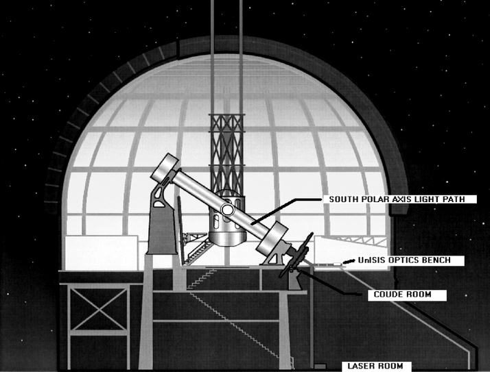
Fig. 1.— Schematic drawing of the Mount Wilson 2.5 m telescope and dome showing the location of the laser room, the UnISIS adaptive optics bench, the coudé room, and the coudé beam path along the south polar axis of the telescope.
The input beam from an equatorially mounted telescope rotates at the sidereal rate when the beam is sent onto a fixed optics table at the coudé focus, so the telescope pupil image, with the shadow of the secondary mirror support struts, rotates on the fixed UnISIS deformable mirror. Indeed, the telescope beam rotates on all fixed elements along the UnISIS beam line, and the final science focal plane would also rotate if countermeasures were not taken. While it is possible to remove this beam rotation at the interface between the telescope and the coudé optics bench (with a reflective "dove prism" rotator), this option was not adopted, and corrective action is taken only at the final science focal plane. The visual‐wavelength science CCD is on a mechanical rotation stage, and images collected at the near‐IR science detector are image postprocessed to remove field rotation.
2.1. Subsystem Drift and Alignment Criteria
UnISIS consists of three subsystems: the laser itself with its projection optics, the adaptive optics bench, and the 2.5 m telescope system. These three subsystems have to be co‐aligned to high precision. Four degrees of freedom are required to co‐align one optical system relative to another: these represent a fixed x, y position of the optical axis and the two direction cosines of the beam. The tip‐tilt controls on a pair of mirrors will suffice to link one subsystem to another. Figure 2 shows a side view of the two‐mirror beam‐transfer system that carries the telescope coudé optical axis onto the UnISIS optics bench. As the figure shows, these two mirrors are relatively close to the coudé focus. A similar two‐mirror interface links the laser projector to the system optical axis.
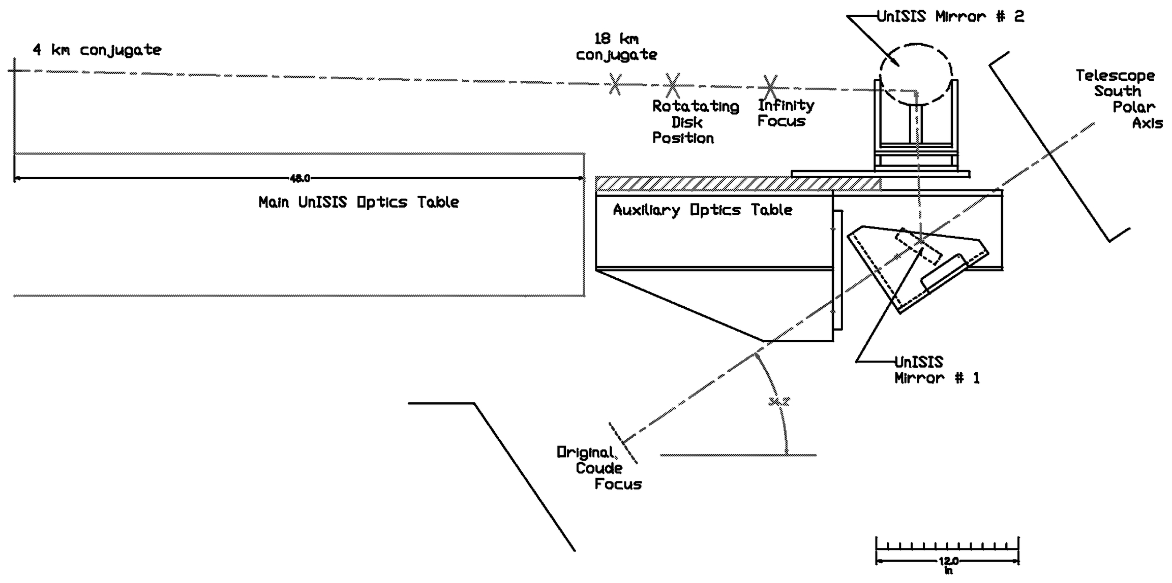
Fig. 2.— Schematic drawing showing the coudé light path coming down the south polar axis of the telescope and being redirected by UnISIS mirrors 1 and 2 onto the main UnISIS optics table. The two mirrors are separated laterally (perpendicular to the plane of the drawing) by approximately 30 cm. UnISIS mirror no. 2 is shown in a dashed outline because this view shows its back side.
The three main subsystems of UnISIS drift in time with respect to one another with amplitudes that are large enough to affect system performance. When UnISIS is prepared for operation, the main optics table is taken as the primary reference, and the other two subsystems are brought into co‐alignment with this reference. At the image scale of the f/30 coudé focus (2 75 mm−1), x, y position alignment to 025 requires a precision of 90 μm, a specification that is not difficult to achieve. The angular co‐alignment specification between subsystems is set by the strict acceptance angle criterion of the high‐speed shutter that sits in front of the laser guide star wavefront camera; this vector co‐alignment must be better than one part in 105, ∼2
''. During initial UnISIS tests, and before the alignment procedure became standard, the return laser guide star signal would appear and disappear depending on whether this angular alignment was within the ∼2
'' range or not. This is no longer an issue.
75 mm−1), x, y position alignment to 025 requires a precision of 90 μm, a specification that is not difficult to achieve. The angular co‐alignment specification between subsystems is set by the strict acceptance angle criterion of the high‐speed shutter that sits in front of the laser guide star wavefront camera; this vector co‐alignment must be better than one part in 105, ∼2
''. During initial UnISIS tests, and before the alignment procedure became standard, the return laser guide star signal would appear and disappear depending on whether this angular alignment was within the ∼2
'' range or not. This is no longer an issue.
Current alignment procedures are routine and take approximately 20–30 minutes at the beginning of an observing session. Realignment is generally required on a daily basis, but if day‐to‐day temperature changes inside the telescope dome are small, the system alignment will hold. As we best understand, the subsystem drifts are caused by the following effects. First, the ground‐floor laser room is on a solid foundation and is unlikely to shift. However, the UnISIS coudé optics table rests on a metal framework bolted to the cement shell that forms the enclosure for the original coudé spectrograph. This 10 m high cement shell slowly rises, falls, and twists with changes in the temperature. No doubt, a similar differential motion of the telescope optical axis occurs when the telescope's two steel piers expand and contract with ambient temperature changes. These changes occur on ∼12 hr timescales and have little impact on the performance of UnISIS during a single night.
3. RAYLEIGH LASER GUIDE STAR SYSTEM DESIGN
3.1. Basic Considerations
The return flux from a Rayleigh laser guide star depends on atmospheric molecular and aerosol backscatter coefficients as well as on the absorption coefficient for the wavelength of interest. The integrated atmospheric absorption (from the ground to the altitude of the laser guide star, which includes low‐altitude Rayleigh scatter) enters the relationship as a square because it acts in both the uplink and downlink laser paths. These radiative transfer details will be described elsewhere (L. A. Thompson & S. W. Teare 2002, in preparation), and here it is sufficient to say that photons at 351 nm are ideal for creating laser guide stars because the Rayleigh scattering coefficient is high as a result of the λ−4 wavelength dependence, and the absorption coefficient is relatively low at 351 nm. Ozone becomes a strong absorber only at wavelengths shorter than 345 nm.
For Rayleigh beacon systems, the laser must be pulsed to allow range gating, which also provides a "heartbeat" to coordinate the system timing. Immediately following the laser pulse, strong Rayleigh backscattered light from low and intermediate altitudes must be rejected by a high‐speed electronic shutter system capable of opening during the precise interval when the backscattered return signal arrives from the high altitude. Continuous lasers can be used for Rayleigh laser guide stars but only if they are mechanically chopped.
The optical system used to transmit laser light to altitude can be one of two types: (1) a small collimator that transmits a uniformly narrow column up through the atmosphere or (2) a large focusing element that transmits a converging beam focused to a specific altitude (see Foy & Labeyrie 1985; Gardner et al. 1990; Hardy 1998, and references therein). While this choice is normally made based on the laser beam quality—a poor laser beam quality requiring a large focusing element—to make a laser transmitter "stealth qualified," a high‐quality laser beam could be transmitted with a large focusing element. Note that UnISIS employs the second of these two options with the 2.5 m primary mirror acting as the focusing element because the laser beam quality is poor. The UnISIS laser beacon is focused ∼18 km above the telescope. Because Mount Wilson Observatory is located 1.8 km above sea level, the laser guide star return signal comes from an atmospheric layer ∼20 km above mean sea level. A schematic representation of the laser beacon projection is shown in Figure 3.
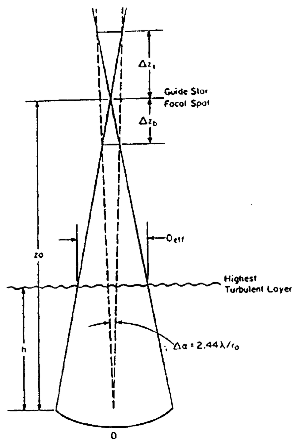
Fig. 3.— Schematic representation of the laser projection geometry in a full aperture broadcast mode. The telescope primary mirror is labeled D, but if it is partially illuminated, D is replaced with Dp. The focus height of the laser beam is zo, and the distances from zo to the top and bottom of the Rayleigh‐scattered return region are, respectively, Δzt and Δzb.
3.2. Integrated Laser Guide Star Depth
The light from the outgoing laser beam fills the conical volume shown in Figure 3. The base of the cone is at the primary mirror of the 2.5 m telescope and its tip sits at a distance of 18 km. Once the laser light reaches the tip of the cone, it passes through a beam waist and fills an inverted conical volume that starts at 18 km. The usable laser guide star return signal comes from the double conical volume limited by the lines labeled Δzt and Δzb in Figure 3. The total length Δz for optimal return is derived in Thompson & Gardner (1989) to be
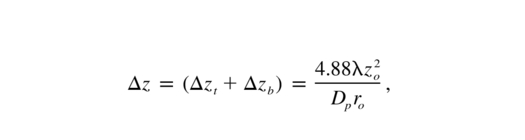
where all symbols in this equation are defined in Figure 3 except λ, which is the wavelength of the laser transmission, and ro, the Fried seeing cell size for the laser projection wavelength. This criterion for Δz assumes that the limit for the lateral dimension of the time‐gated laser return signal (as viewed from a distance zo) equals the atmospheric seeing size for the laser wavelength. Note the inverse dependence of Δz on Dp so that a smaller laser beam footprint on the telescope primary mirror allows a deeper illuminated volume to contribute to a seeing‐limited laser guide star image. The Thompson & Gardner relationship was devised for a telescope with no central obscuration, so a point of diminishing returns will occur with UnISIS if (to gather more return flux) Dp is decreased to the point where it begins to approach the diameter of the Cassegrain secondary mirror. For UnISIS,
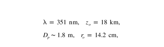
where the value for ro is scaled to the laser wavelength but is otherwise taken from the 500 nm median value of ro as reported by Walters & Bradford (1997) for Mount Wilson and implies that the median Mount Wilson seeing is between 07 and 08 at visual wavelengths. In these conditions, the predicted depth for the integrated laser volume is Δz = 2.2 km. The value used above for Dp is discussed below. Additional information on the astronomical seeing at Mount Wilson is provided in Teare et al. (2000), and Teare & Thompson (2002) show that there are long‐term trends in the seeing profile.
3.3. Questek Excimer Laser
Figure 4 shows the Questek 2580vβ excimer laser system used to produce the UnISIS laser guide star. This laser operates in a pulsed mode with pulse length ∼20 ns, repetition rates programmable up to 500 Hz, and an average power of approximately 30 W. (Each laser pulse is ∼90 mJ, and since the laser power scales directly with the repetition rate, 30 W is the nominal laser power for the 333 Hz UnISIS mode of operation.) The output beam quality is poor compared to other laser systems, but beam quality can be corrected with appropriate optical components as described below. The Questek 2580vβ was purchased in 1990 and was used in both the Thompson & Castle (1992) Rayleigh guide star experiments and the laser guide star work of Neyman (2002) before being moved to Mount Wilson.
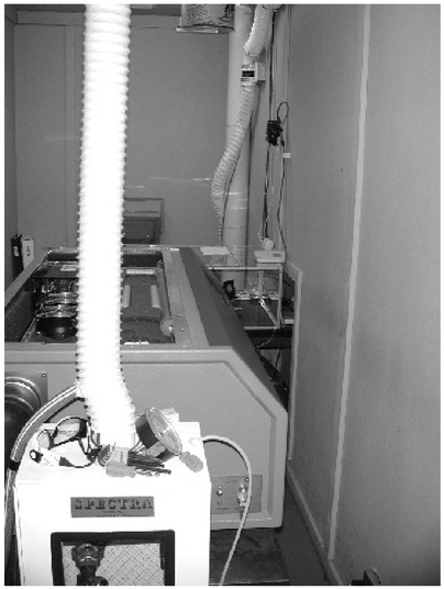
Fig. 4.— Photograph of the Questek laser with the top cover removed. In the foreground is a sealed cabinet holding the fluorine gas with a vent hose exiting the top of the cabinet. The chamber that holds the lasing gas mixture is just to the right of the vent hose, and the laser capacitor banks are below the fans visible on the left of the vent hose. The laser beam exits on the far side of the laser cabinet.
When plane‐parallel laser mirrors are mounted at both ends of the laser chamber, the natural divergence of the excimer laser beam is ∼3 mrad, approximately 103 larger than required for creating a laser guide star close to the seeing limit. Better performance is obtained in two steps. First, the planar laser mirrors are replaced with a pair of curved windows that form a miniature Cassegrain telescope. The rear laser mirror acts like a primary and the front laser mirror acts like a Cassegrain secondary mirror. In this configuration the laser is said to have an unstable resonator cavity. Figure 5 shows the cavity and the photon amplification paths. This laser amplification proceeds as follows. Seed photons in the core of the laser beam that happen to be traveling in the forward direction hit the convex front laser mirror and travel in the backward direction through the laser chamber. These backward‐traveling photons are amplified and expand to fill the rear laser mirror. The rear laser mirror is concave and is designed to collimate photons reflected off the front laser mirror. In the final forward pass through the lasing chamber, these amplified seed photons sweep a large fraction of the energy from the lasing medium and emerge from the front laser window as the output pulse. In the process of beam expansion within the laser chamber by the Cassegrain optical system, the laser beam divergence is reduced from 3 mrad to approximately 300 μrad (G. Caudle 1999, private communication). If this beam were transmitted into the upper atmosphere without further modification, the laser would produce a small focused spot approximately 62 '' across. This beam divergence is still too large by a factor of 100 to create a useful laser guide star.
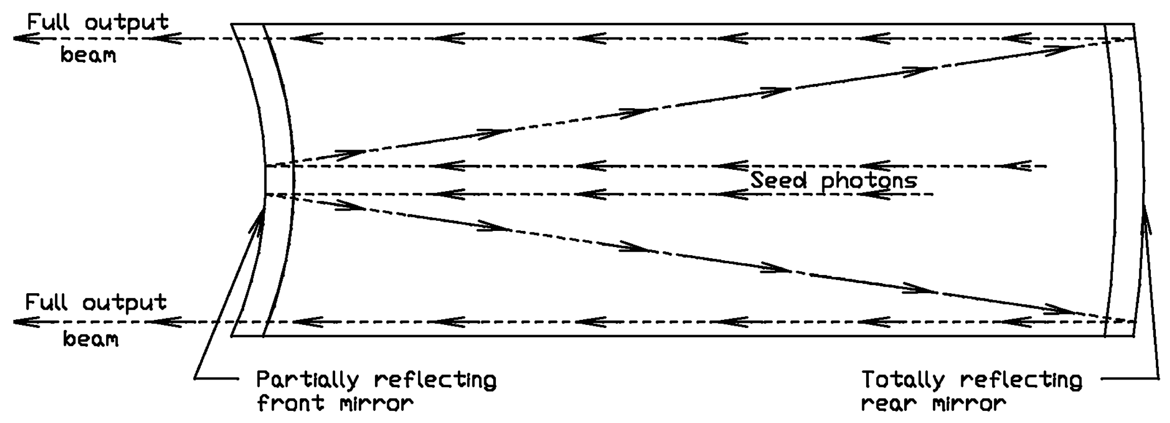
Fig. 5.— Schematic drawing showing how photon amplification occurs in an unstable resonator cavity.
3.4. Full‐Aperture Laser Projection
The output beam from the Questek laser is approximately 9 mm × 22 mm, and it is this beam that has a nominal divergence of 300 μrad. If a small divergent beam of diameter d is expanded to fill a collimator of diameter D, the divergence in the final beam is reduced by the factor D/d. For UnISIS, the focusing element is the telescope's primary and secondary mirrors. If we adopt d = 24 mm for the circle that encloses the raw laser beam and D = 2.5 m for the largest focusing element, the divergence is 2.9 μrad (06) after it is beam‐expanded and projected into the sky off the 2.5 m primary mirror.
This logic sets the design strategy for projecting the UnISIS laser beacon into the sky. The true situation is somewhat more complex for the following reasons: (1) the laser beam is masked and only part of the 9 mm × 22 mm makes it to the telescope pupil; (2) the remaining laser beam is expanded to fill only a central 1.8 m portion of the primary mirror (see below); and (3) the unstable resonator optics in the Questek 2580vβ do not produce a perfectly collimated output beam. Instead, the laser beam has an empirically measured beam divergence of 620 μrad, which consists of the quadrature sum of the random divergence (300 μrad) and a "mechanical" or "optical" divergence (540 μrad). The imperfect optical divergence of the laser is easily corrected with the laser projection optics (described in § 4.3 below).
Experimental tests of laser projection from Mount Wilson confirm that laser guide stars as small as ∼08 FWHM can be produced under good seeing conditions as long as the integrated depth of the laser guide star Δz is kept below 2.2 km as calculated above. Although Mount Wilson Observatory is no longer a dark site (Teare 2000), the U‐band sky brightness does not degrade the laser return signal because the laser guide star sits significantly above the sky background light equivalent to a ninth or 10th magnitude star.
4. BEAM SHARING AND SYSTEM TIMING
After the 351 nm beam exits the laser on the observatory ground floor and passes into the coudé room, it is converted into an f/30 to f/40 diverging beam so that it can join the telescope optical axis and be projected into the sky. The major design complication is how to allow the laser projection system to beam‐share the optical axis with the incoming astronomy light. In the laser‐guided adaptive optics system at the Starfire Optical Range, the beam‐sharing element was a solid cube beam splitter (Fugate et al. 1994) that had the unfortunate property of fluorescing because of the very high flux of laser light that passed through it. This fluorescence produced a relatively continuous flux of background light that prevented the detection of low surface brightness astronomical objects.
4.1. Rotating Glass Disk
To avoid fluorescence, the UnISIS beam‐sharing scheme consists of a rotating disk with small reflective spots deposited on its front surface. The laser light is directed toward the rotating glass disk (at an angle of incidence of ∼22°), and at the exact moment when the reflective spot is sitting on the telescope optical axis, the laser is fired. Once the laser fires, the outgoing laser pulse hits the small reflective spot and is sent into the sky along the telescope's optical axis. As quickly as the light travels up to ∼18 km and back, the small reflective spot moves off the optical axis and the laser guide star light traces a reversed path, passes through a clear area on the rotating disk, and proceeds into the UnISIS adaptive optics system.
Astronomy light from the sky passes through the rotating disk at all times and into the adaptive optics system. The fraction of lost astronomy light (reflected from the spots) is at most ∼5.5% (the area obscured by the spots). Because these spots are multilayer dielectric coatings, they appear nearly transparent at visible wavelengths, so the amount of light lost to the science cameras is likely to be less than 2%. Figure 6 shows a picture of the rotating disk assembly sitting on a table after being removed from the optical system. The disk itself is 0.25 inch thick UV‐grade fused silica with excellent surface flatness and an outer diameter of 5 inches. Multilayer dielectric reflective spots (R = 99.9% at 351 nm) are deposited in sets of three (the three‐spot configuration is explained in Thompson & Xiong 1995) at radii of 41.6, 45.6, and 49.6 mm. These spots are hardened to withstand laser powers as high as 4–6 J cm−2.
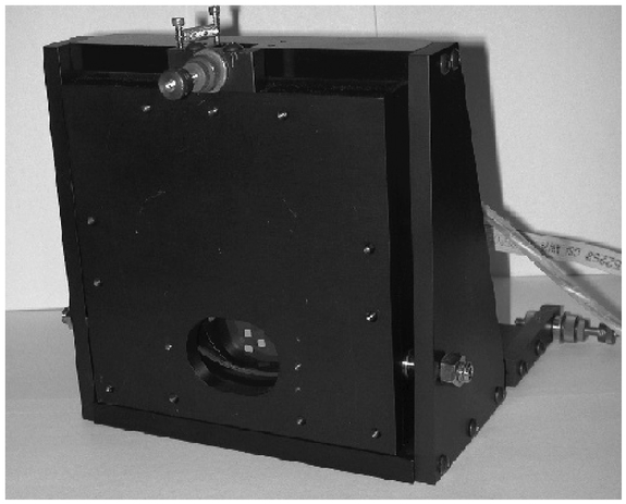
Fig. 6.— UnISIS rotating disk assembly was removed from the optical system for this picture. A set of three reflective spots can be seen through the front face of the mounting.
Glass disks of 5 inches diameter have sufficient strength to withstand the rotational stress of 10,000 revolutions per minute (rpm), and the disk shown in Figure 6 rotates at this rate. The rectangular reflective spots are 3.4 mm in the radial direction and either 4.2 mm (for the inner spot) or 4.7 mm (for the two outer spots) in the azimuth direction. The reflective spot size is set by the requirement that they must rotate out of position fast enough to allow the return light from altitude not to be obscured when it returns from ∼18 km altitude. For the UnISIS disk specifications, this requirement is met for Rayleigh backscatter altitudes 14.5 km and higher, a range that corresponds to the low edge of the laser guide star range gate (Δzb in Fig. 3).
If just one reflective spot were deposited on the disk, at 10,000 rpm it would appear on the optical axis 167 times per second, and this would set the frequency or heartbeat of the wavefront sensing in UnISIS. Because closed‐loop performance of an adaptive optics system might suffer if it were run at this rate, pairs if spots are deposited on the disk at 180° separations, which allows 333 Hz adaptive optics operation. For the sake of redundancy, four sets of spots are deposited on the disk (at 90° spacing) as a fallback, should any of the spots be damaged by the high laser energy density (which indeed has happened).
Because the laser light reflects off the front surface of the rotating disk, a tight specification had to be set for the extent to which the motor shaft is perpendicular to the front surface of the disk. Otherwise, in 333 Hz operation, the angle of incidence for the reflected beam would be different for every other spot, and the laser guide star at altitude would move from side to side every other pulse. The mechanical specification for the disk relative to its shaft was set at less than 3 ''. The acquisition of the UV‐grade fused‐silica disk was relatively simple, but getting the glass disk attached to the motor shaft to the required level of precision was more difficult.
4.2. UnISIS System Timing
UnISIS requires the synchronization of three subsystems to complete one cycle of operation. First, the spots on the rotating disk must be synchronized with the arrival of the outgoing laser energy so that the 351 nm light is directed out the telescope. Second, the Pockel's cell shutter must be opened at the appropriate time to receive the return signal. Third, the wavefront sensing camera must be triggered to receive the return pulse from the 18 km focus.
The master clock for this system is the rotating disk controller, a stand‐alone embedded microprocessor system, which reads a motor encoder on the rotating disk. This encoder provides an indicator giving the position of reflective spots. When the spots are in the correct orientation, it sends a TTL pulse to the laser system. In order to trigger the laser precisely (to within 10 ns accuracy) the laser is left in its fully charged configuration, waiting for a pulse from the rotating disk controller. The rotating disk controller has external dip switches used to manually enter a phase delay between the rotating disk spot positions and the laser trigger pulse. The rotating disk is viewed in a stroboscopic mode in order to set the phase delay and get the laser to fire when a reflective spot is exactly on the optical axis.
Immediately after the laser fires, an optical fiber photovoltaic converter (placed at the edge of the outgoing laser beam) senses the outgoing laser pulse and generates a TTL pulse. This TTL pulse is sent to a digital delay/pulse generator (Stanford Research Systems Model DG535), which is connected by BNC cables to the high‐voltage drivers for the Pockel's cell switch and to an external "strobe" line into the camera electronics of the laser guide star wavefront sensor. By dialing appropriate time delays into the digital delay generator, the Pockel's cell shutter is opened and closed at the appropriate times (i.e., the speed of light travel time to zo - Δzb and zo + Δzt) and for triggering the exposure of the wavefront sensor CCD. The CCD camera then passes a data frame to the wavefront reconstructor, a separate stand‐alone computer with eight internal digital signal processors connected in parallel. The reconstructor calculates the wavefront corrections to be passed to the 177 actuator Xinetics deformable mirror electronics and a single cycle of wavefront correction ends. UnISIS is currently run at three repetition rates: 17 Hz for testing and system setup, 167 Hz operation mode to match nights when atmospheric wavefront timescales are slow, and the 333 Hz mode to match nights when atmospheric timescales are fast.
4.3. f/30 Laser Projection Optics
As mentioned above, the laser reflective spot must rotate off the optical axis rapidly enough to allow the return Rayleigh light to pass through a clear area on the rotating disk. This requirement, and the fact that glass disks will not withstand arbitrarily high rotation rates, means that the reflective spot must be small and that the laser beam must be reduced to a small dimension before it encounters the disk. This adds just a few complications to the system design: the beam from the laser must be reshaped anyway from its very gentle 540 μrad divergence to match the ∼f/30 coudé beam. This reshaping is done in the coudé room in the vicinity of the 18 km conjugate point, a point that is located 328 mm beyond the coudé infinity focus. The details of this beam reshaping were first discussed by Thompson & Xiong (1995).
In quick summary, the laser light passes along the following path. The beam emerges from the front laser port in the basement laser room, hits three flat beam‐directing mirrors (used for subsystem co‐alignment), and travels vertically for ∼11 m where it encounters an adjustable razor blade pupil stop. At this point, the laser beam has expanded to 14 mm × 28 mm, but the razors are used to reduce the beam to 14 mm × 24 mm to avoid spillover onto the rotating disk beyond the reflective spot. The clipped beam then passes through an air‐spaced doublet that forms a relatively fast converging beam, as shown in Figure 7. Just before this beam reaches focus, it enters a small diverging lens that converts the clipped laser beam into the expanding ∼f/30 beam that hits the rotating disk and travels up the telescope south polar axis. The beam then hits the tertiary, secondary, and primary mirrors and is transmitted to the 18 km focus. Figure 8 shows two images of the laser beam, one in its full rectangular form and the other clipped and on its way to up the telescope's south polar axis.
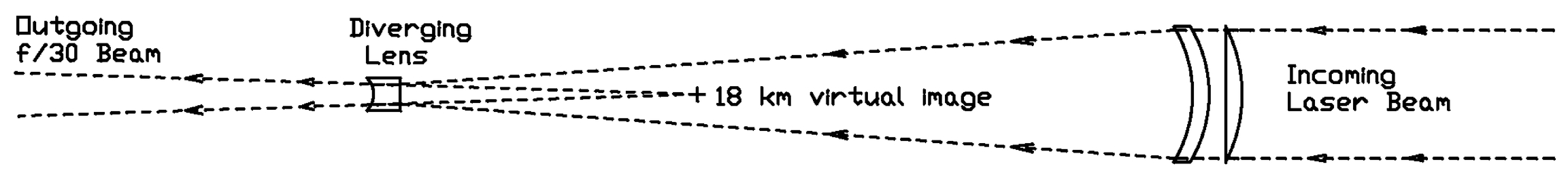
Fig. 7.— Three simple lenses are used to convert the (nearly) collimated laser beam into f/30 for projection with the 2.5 m telescope optics. The "air‐spaced doublet" is on the right and the "diverging lens" on the left. These lenses represent surfaces 2–14 in Table 1. Note that the design has no concave surfaces with radii on the right, a necessary condition to avoid back‐reflected laser hot spots. The point labeled "18 km virtual image" is placed at the 18 km conjugate point in the 2.5 m telescope system to guarantee that the laser guide star focuses at the preselected altitude.
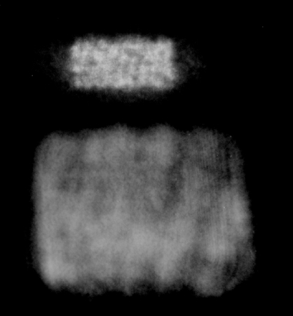
Fig. 8.— Top: Excimer laser beam before it encounters the razor beam stop. At this point (∼9 m from the laser exit port) the beam is approximately 14 mm × 28 mm. Bottom: Laser beam as it exits the coudé room on its way up the south polar axis. This beam is ∼55 mm across the diagonal at this point. Interference fringes are visible in both images, but the peak intensity in the center of the fringes exceeds the uniform background only by ∼10%. The fringes are intrinsic to the laser and probably arise from interference phenomena within the front and or back laser mirrors. The laser mirrors have a dielectric coating deposited on their external face (to prevent fluorine gas from attacking the dielectric material), so lasing photons pass through the glass at both ends of the laser chamber.
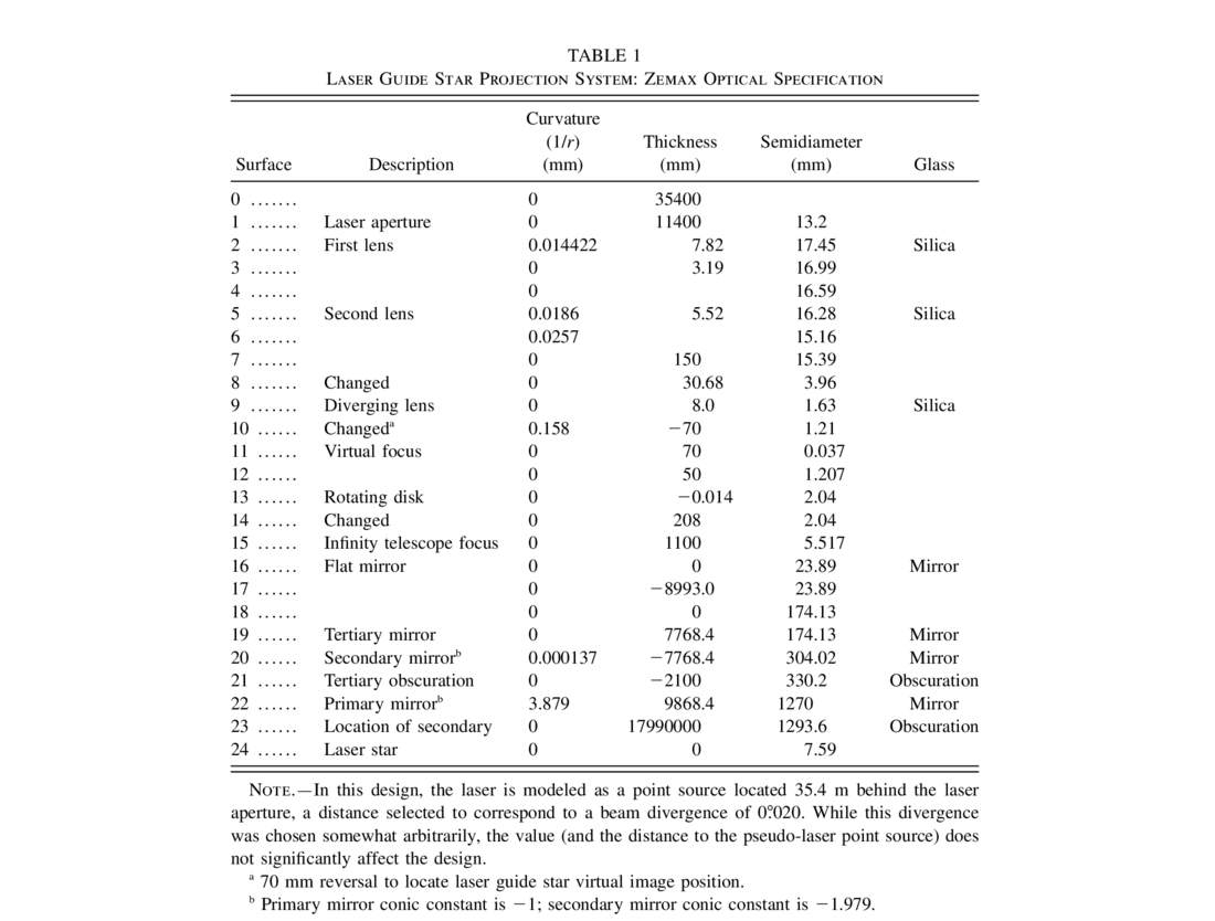
The three‐element UV‐grade fused‐silica optical system is designed to create a virtual image of the laser guide star 70 mm behind the back surface of the small diverging lens. By placing these three optical elements in a position such that the virtual image of the laser guide star sits at the conjugate focus of the 18 km layer (namely, 328 mm beyond the infinity focus), the combined optical system that includes the telescope primary mirror creates a concentrated region of laser energy some 18 km above the primary mirror with a waist ∼52 mm in diameter (2.9 mrad as seen from the primary mirror), with additional smearing caused by atmospheric blurring. The Zemax optical design for this laser projection system (including the 2.5 m telescope optics) is given in Table 1.
 |
The air‐spaced doublet in the three‐element optical system is mounted in a cell that can be moved along the optical axis while the diverging lens remains fixed. As the doublet moves, the output f/ratio and the location of the virtual image conjugate point change simultaneously. By watching the laser return signal with a test camera focused on the 18 km layer (see § 7 below), the position of the air‐spaced doublet can be optimized for the best focus at 18 km. In the most recent experimental tests, the optimal laser guide star focus occurred at a somewhat slower output beam than expected (∼f/39), and hence the laser pupil does not completely fill the primary mirror. This has the effect of slightly increasing the focal spot size at 18 km from the ideal 52 mm value given above, but this does not degrade the performance significantly because the limiting angular size of the laser guide star is dominated by atmospheric blurring in the round‐trip uplink and downlink paths. The fact that the beam is being transmitted at ∼f/39 means that the laser beam footprint on the primary mirror is somewhat less than the full 2.5 m aperture and hence the value given above for Dp ∼ 1.8 m.
The alignment and positioning of the three‐element laser projection optical system is very critical to good performance of UnISIS. The better focused the laser guide star is, the more accurately the Shack‐Hartmann wavefront sensor can determine the wavefront error. The process of focusing the laser guide star is somewhat dangerous because the energy density in the converging beam—at the point just before it enters the small diverging lens—becomes quite large. Slight misadjustments in the positions of the three projection lenses can cause the energy density to rise above the damage thresholds of the optical coatings. Coatings on these lenses (and on the multiplayer dielectric spots on the rotating disk) were applied by Acton Research Corporation (Acton, MA) and have damage thresholds of 4–6 J cm-2. One accident did occur where the converging beam was allowed to shrink too much, and it exceeded the damage threshold given above. Figure 9 shows the results. Newer diverging lenses have now been installed in UnISIS with dielectric coatings applied by Alpine Research Optics (Boulder, CO). These have a damage threshold of 17.5 J cm-2.
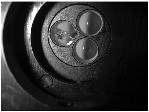
Fig. 9.— Greatly enlarged image of the diverging lens holder. While three lenses are held by a single mount, only one is used at a time. Two pristine diverging lenses can be seen on the right, and the one damaged diverging lens is on the left. The damage occurred when the energy density sent into the lens exceeded 6 J cm-2 at the rear surface of the lens. To set a scale for this image, each lens has a diameter of 7.4 mm.
5. FAA AND LASER SAFETY ISSUES
When compared to other laser guide star systems, UnISIS has a clear advantage in being generally benign to both aircraft and satellite interference. In this regard, UnISIS might be called stealth qualified. Because this characteristic affords great convenience in the nighttime operation at Mount Wilson, it is appropriate to describe how this was achieved. The situation begins with the fact that 351 nm light is invisible to the eye, and it is further aided by the need for full‐aperture laser projection as explained in §§ 3.3 and 3.4 above. Full‐aperture laser projection significantly dilutes the laser beam intensity at all altitudes except in the focused beam waist at ∼18 km. Laser guide star projection systems that project at visible wavelengths and those that use a relatively small collimators are required by the Federal Aviation Administration (FAA) to implement safety procedures that include airplane spotters located outside the telescope dome.
The surface energy density of the UnISIS laser beam as it leaves the telescope primary mirror is very dilute. A person who might accidentally stand in the beam at a point immediately outside the telescope dome would receive a continuous UV flux approximately equal to the UV flux one would receive from the Sun in the same 350 nm region of the spectrum. The 351 nm light—from the Sun or from a laser—is of sufficiently low energy that it does not damage proteins in the body so it will not lead to the formation of cancer, but it can penetrate the aqueous humor of the eye and cause cataracts, so laser‐safe glasses are used by the UnISIS team and the telescope operators who are in the dome on nights when the laser is being transmitted. Laser‐safe eyeglasses or goggles are required in the laser room and in the coudé room, where the laser beam is hot and the scattered UV photon flux is substantial.
When the telescope is pointed to the zenith, the UnISIS laser beam comes to a waist at 20 km above mean sea level, which corresponds to 66,000 feet. Because seeing degrades as a function of zenith distance and because differential refraction (between the UV laser guide star and the near‐IR wavelengths of the science cameras) increases as a function of zenith angle, there are no plans to use UnISIS farther than 40° from the zenith. Therefore, the minimum altitude for the laser guide star beam waist is 15.3 km (50,000 feet), so commercial aircraft are not likely to enter the focused region of the laser guide star. However, at the altitudes of air traffic the energy flux (in J cm-2 per pulse) in the laser beam will be greater than that immediately in front of the primary mirror, but to counter this point we note that photons at 351 nm are absorbed by the glass and the plastics that are used in aircraft windows.
In a white paper sent to the FAA in 1997, the UnISIS laser was called a "single pulse laser" from the perspective of an airplane pilot or passenger. The maximum operating pulse rate of the UnISIS laser is 333 Hz. If we assume an airplane window is 30 cm across, an airplane would have to be flying slower than 30 m s−1 (67 mph) for two pulses to enter the window. This is much slower than the speed of an average airplane. ANSI standards list specifications for single‐pulse lasers in terms of the power per pulse at a given wavelength, and the dilute beam of the UnISIS laser—in the altitude range where commercial planes fly—places the UnISIS laser with Class I systems (eye safe), even if the laser photons were able to pass through glass or plastic windows. One of the main worries of the FAA is the distractive nature of a laser beam in the sense that a pilot notices the emission. Since 351 nm light is invisible to the eye, this is not an issue either.
After initial telephone contact with the Western‐Pacific Region of the FAA in Los Angeles, California, and after explaining the circumstances described above, the FAA requested a written report restating the case. Approximately 4 months after the FAA received the UnISIS report, they issued a letter that stated, "Propagation of Class I lasers into navigable airspace pose no hazard to aviation and we have no objection to the operation described in your correspondence. Please advise our office of any proposed changes or alteration to your proposed scientific research laser installation in order that an aeronautical study may be accomplished to determine the effect of the changes on the safe and efficient use of navigable airspace by aircraft."
6. OPTICAL ALIGNMENT AND FOCUS METHODS
6.1. Subsystem Co‐Alignment
As described above (§ 2.1), there are relative drifts over ∼12 hr periods between the three UnISIS subsystems. This persistent problem made it necessary to understand and carefully control the UnISIS optical alignment. This exercise came to a successful end after a few hard rules were imposed. These included (1) to define with great precision a single vector on the UnISIS adaptive optics bench as the primary system reference, (2) to align each subsystem separately and only then pull them together as a whole, and (3) master the chromatic problems associated with the alignment of refractive optics that work at 351 nm but must be aligned, at least initially, at the more convenient 635 nm laser diode wavelength. These issues are discussed in turn.
The single reference vector on the UnISIS adaptive optics bench is defined with two mechanical reference points. One of these is a small (but removable) pinhole that sits in the center of the primary telescope focal plane (at the f/30 infinity focus). The second reference point is a removable pointlike target located 1.5 m beyond the infinity focus. A small but very bright diffraction‐limited laser diode beam is forced through these two mechanical points no matter where the UnISIS optics bench happens to sit as it "floats" on its underlying support structure. This reference beam is used to co‐align the individual components in the adaptive optics section of UnISIS, and then the same is done for all components in the laser guide star projection subsystem. Except for chromatic effects discussed below, this procedure works well. Then, a second reverse‐traveling 635 nm diode laser reference beam is co‐aligned with the first, and this second beam is propagated up through the coudé optical train of the telescope. Using the tip‐tilt action of the two mirrors shown schematically in Figure 2, the telescope subsystem is finally brought into co‐alignment with the other subsystems. As noted above, the procedure defined in this paragraph takes approximately 20–30 minutes to complete.
The chromatic alignment problems in the refractive sections of UnISIS were the most difficult to understand and defeat. There are two refractive systems within UnISIS: (1) the laser guide star projection system (described in § 4.3 above) and (2) the UV wavefront sensor optics that include the Pockel's cell shutters and the EEV wavefront sensor camera (described in L. A. Thompson et al. 2002, in preparation). One very convenient procedure for aligning a lens‐based system is to send a narrow pencil‐beam laser through the optical train and search for faint retroreflected and focused ghost images that are formed by each curved (lens) surface. These focused ghost images sit at 1 / 2 × the radius of curvature of each optical surface. By identifying the positions of both ghost images (one on the front side and one on the back side of a standard double convex lens), the tip‐tilt and the x, y centroid for a single lens can be set, one lens at a time. While this is a straightforward procedure, even the slightest angular misalignment between the 635 nm reference beam and the true 351 nm entrance vector can produce significant errors in the alignment, especially if there are multiple lenses in the system because the position of the 635 nm alignment vector gets displaced, one lens after the next, relative to the 351 nm vector by refractive effects within each lens. The only way to remove these ambiguities is the use 351 nm light as the final check on the alignment. While 351 nm photons are difficult and inconvenient to use in alignment exercises (because they are not visible to the human eye), 351 nm photons are indirectly detectable because they produce a blue fluorescence on a high cotton content paper target. Careful cross checks of the 635 nm alignment with 351 nm laser light made it possible to eliminate the chromatic effects in the refractive sections of UnISIS.
6.2. Laser Guide Star Focus and Alignment
The laser‐guided adaptive optics system built at the Starfire Optical Range (Fugate et al. 1994) introduced the important concept of calibrating the laser guide star wavefront signal during closed‐loop operation on a natural star. As described in another paper (L. A. Thompson & S. W. Teare 2003, in preparation), UnISIS incorporates this design concept from Fugate et al. Although it requires simultaneous operation of two wavefront cameras, one for a natural star and the other for the laser guide star, this technique unambiguously removes the non–common‐path aberrations that inevitably exist between the laser guide star wavefront optical path and the natural star optical path. In UnISIS, the natural star wavefront sensor used for this calibration is situated immediately before the final science camera focal plane. By running UnISIS in closed loop on a natural star and (in open loop) recording a Shack‐Hartmann wavefront reference frame for the laser guide star, this calibration technique delivers to the wavefront computer system what we call the "laser wavefront Shack‐Hartmann reference frame." Only after recording this calibration frame is UnISIS run in closed loop with the laser guide star. The wavefront computer is instructed to drive the deformable mirror not to the mechanical null of the laser guide star Shack‐Hartmann sensor but to the null of the laser wavefront Shack‐Hartmann reference frame. Even if there are uncalibrated optical offsets in the laser guide star optical system (e.g., problems of focus or astigmatism), the natural star calibration method circumvents these problems and the adaptive optics system drives to a null representing the diffraction‐limited performance of the natural star calibration. In this way, we avoid the need to establish the absolute true focus and alignment of the laser guide star wavefront system.
7. TIME‐GATED IMAGE TUBE CAMERA
During the UnISIS system development, a time‐gated image‐intensifier camera was used repeatedly to identify and diagnose problems with the laser guide star system alignment and focus. There was simply no other convenient means available to detect the faint high‐altitude laser guide star return signal in the presence of the low‐altitude and very bright foreground Rayleigh‐scattered light. When the CCD wavefront sensor was used without its Pockel's cell shutter, it was quickly driven into saturation by the high‐intensity but low‐altitude Rayleigh‐scattered light.
The time‐gated Reticon camera functions essentially the same as the primary UV wavefront sensor system, with the following modifications. Instead of sending the TTL output of the digital delay generator to the Pockel's cell switches, this signal is sent to the high‐voltage gated input line of the image intensifier. When the intensifier is off, the Reticon sensor is blind (to the low‐altitude Rayleigh flash). For laser guide star tests, the intensifier is turned on only for the short time interval (13–17 μs long) when the backscattered photons are returning from high altitude. Even though the image intensifier is nonlinear and must be handled cautiously in the presence of the bright outgoing laser pulse, a tool of this kind is invaluable to those who contemplate developing a Rayleigh laser guide star system.
8. SHACK‐HARTMANN WAVEFRONT TESTS
The UnISIS UV wavefront sensor is designed to work in coordination with the UnISIS Rayleigh laser guide star system to produce Shack‐Hartmann signals to drive the UnISIS deformable mirror. Prior to the laser guide star tests described below, operation of the wavefront sensor was validated in the following two ways:
- 1.An artificial laser guide star was sent through the UnISIS optical system by mounting a UV transmitting fiber optic on an x‐y‐z mechanical stage and positioning the fiber at the 18 km conjugate point on the UnISIS optics bench. The input end of this fiber was fed 351 nm light from the Questek laser in such a way that the output end of the fiber optic produced a uniformly illuminated f/30 output beam. With the dome closed and with the Questek laser placed in full operation, an external pulse generator was used to trigger the laser, the Pockel's cell shutter, and the CCD camera to produce test wavefront images.
- 2.On an excellent photometric night, the star Sirius was acquired at the normal infinity f/30 coudé focus of the telescope. A focus screen was then installed at the 18 km conjugate focus (328 mm beyond the infinity focal plane), and the telescope secondary mirror was adjusted to bring the starlight into focus at the 18 km conjugate. After removing the focus screen, the light from Sirius was passed through the adaptive optics system and onto wavefront sensor camera. In this case, the CCD camera and the Pockel's cell shutters were run with an external pulse generator, and the CCD exposure time was set to 100 μs (the maximum exposure available with the camera drive electronics). A 10 nm wide interference filter centered at 350 nm was placed in the collimated beam immediately before the wavefront camera. Test exposures from the wavefront sensor were then taken of Sirius.
The wavefront camera system worked as designed for both tests, and then UnISIS was prepared for the Rayleigh laser guide star tests. Nights selected for these tests were of reasonable photometric quality so a return flux comparison could be made with Sirius. Only nights of excellent seeing were used for these tests because the individual pixels in the UnISIS UV wavefront sensor have dimensions of 1'' × 1''. The aim of the test was to focus the laser guide star light on single pixels on the wavefront sensor camera in order to estimate the FWHM of the laser guide star and to measure the strength of the return laser guide star signal. For these tests, the telescope was parked within 1° or 2° of the zenith.
Normally, the lenslet array in a Shack‐Hartmann sensor is positioned for maximum wavefront sensitivity so that Hartmann subimages fall in the center of (at the central intersection of) a 2 × 2 pixel "quadcell." For the test shown here, the 13 × 13 lenslet array was offset from this nominal position in two regards. First, the lenslet array was moved significantly to the lower left (as seen in the two test images reproduced in Fig. 10) to pass light to the sensor without going through the lenslet array. Second, the lenslet array was positioned so that light from single lenses in the lenslet array was centered on a single pixel in the wavefront sensor. This alignment was set immediately before the observing run began, and, based on previous experience, we know that the alignment will remain stable for many hours.
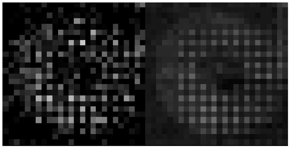
Fig. 10.— UnISIS UV wavefront sensor images from the 18 km laser guide star. Left: Wavefront image from a single laser pulse. Right: Integrated wavefront signal from 45 consecutive laser pulses. As described in the text, the lenslet array was purposely offset to the lower left to show a portion of the bare pupil illuminated with the 351 nm laser light.
Wavefront data shown in Figure 10 were taken on the night of 2001 November 5 UT. On this night, the laser guide star system was operated in the standard test mode with a repetition rate of 17 Hz. The UnISIS reconstructor computer has the ability to direct to a special storage buffer (on external command) 45 consecutive wavefront data frames. For this test, the time gate on the Pockel's cell shutter was adjusted in real time to optimize the focus and the brightness of the lenslet images as viewed through a continuous video output from the UnISIS wavefront reconstructor computer. Note that the laser guide star projection optics were placed at a particular mechanical point set by inspecting the return laser guide star image on the time‐gated Reticon camera, and no effort was made to iterate between the best appearing Pockel's cell setting and this mechanical focus. The Pockel's cells are driven by a TTL pulse (from the Stanford delay generator) and have an 8 μs rise time after the trigger signal is applied to their high‐voltage power supplies. The two time gates given below are for the time interval at half‐maximum transmission and the time interval for 100% Pockel's cell transmission:
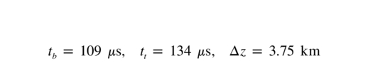
for 50% Pockel's cell transmission, and
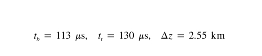
for 100% Pockel's cell transmission
Figure 10 (left) shows the wavefront image from a single pulse of the laser guide star. Notice that several individual pixels are brightly illuminated whereas others are much fainter. This is the expected behavior for a Shack‐Hartmann sensor running in open loop; i.e., wavefront gradients from the turbulent atmosphere momentarily displace individual subimages from their nominal position, in this case centered on single pixels. The 3 brightest pixels in Figure 10 (left) have 27 e-, 25 e-, and 25 e-, whereas the pixels immediately adjacent to the 3 brightest pixels contain an average of 4 e-. This shows that the Rayleigh laser guide star had an FWHM less than or equal to 1 '' (a limit set by the dimensions of a single pixel) on the night of 2001 November 5. Figure 10 (right) shows an integrated sum of 45 consecutive wavefront images. The action of the turbulent atmosphere in this case is to blur the subimages, but their centroids, on average, remain centered on the individual CCD pixels. The total detected signal from the individual bright pixels plus the flux in the 4 adjacent pixels (top, bottom, left, right) is 23 e-.
The UnISIS wavefront sensor used in these tests is a Marconi EEV‐039a with a quantum efficiency of 48% and a system read noise of 4.8 e- rms. A new Marconi EEV‐039a sensor was recently obtained with 68.2% quantum efficiency, and it is expected to have a comparable, or perhaps even lower, read noise. The new sensor returns a signal that is higher by a factor of 1.42. At the time the exposure in Figure 9 was taken, the excimer laser had been running several hours and the power per pulse was 75 mJ, whereas under normal conditions the laser runs at 90 mJ per pulse. Therefore, the UnISIS wavefront camera under normal operating conditions with the new sensor will be detecting ∼40 e- per subaperture at an rms read noise ∼4.8 e- (or better). This performance is perfectly satisfactory for closed‐loop laser guide star operation of UnISIS.
9. CONCLUSION
The UnISIS Rayleigh laser guide star system has been commissioned and operated in open loop with satisfactory return signal for a 13 × 13 set of subapertures across the pupil of the Mount Wilson 2.5 m telescope. A tightly focused laser guide star return signal with an FWHM ∼ 1 '' was received from a Δz = 2.5 km range gate centered at 18.2 km above the telescope (∼20 km above mean sea level). This successful demonstration of the UnISIS laser guide star system sets the stage for closed‐loop operation with the full UnISIS adaptive optics system. The 351 nm Rayleigh laser guide star technique with full‐aperture broadcast provides a reasonable method to monitor wavefront perturbations in the Earth's atmosphere, and it is especially attractive because of its stealth characteristics. Rayleigh laser guide stars are likely to be the basis for many other laser‐guided adaptive optics applications in the future.
A number of people have contributed to the work reported here. This includes Richard Castle, Dr. E. Harvey Richardson, Samuel Crawford, Dr. Xiong Yao‐Heng, Dr. Chris Neyman, and Bill Knight and his machine shop crew. At Mount Wilson Observatory, we acknowledge support provided by Mount Wilson Institute Director Dr. Robert Jastrow and technical assistance by Robert Cadman, Sean Hoss, Chris Hodge, Joe Russell, Victor Castillo, and Thomas Schneider of Schneider Engineering. Telescope operator support at the 2.5 m telescope was provided by Kirk Palmer, Michael Bradford, and Jim Strogen. Information and assistance with the Questek laser system was provided by Dr. George Caudle and Geoffry Bramhall. EEV wavefront camera electronics support was provided by Dr. Robert Leach, Jamie Erickson, and Scott Striet. Assistance with the rotating disk assembly was provided by Geoff Gretton. Advice was also provided by the UnISIS/NSF Advisory Panel that included Drs. Robert Fugate, Doug Simons, Matthew Mountain, David Sandler, Byron Welsh, Ray Weymann, G. Wayne van Citters, and Ben Snavely. This Rayleigh laser guide star research has been supported by grants from the National Science Foundation (AST 89‐18878, AST 92‐20504, and AST 00‐96741) and by funds from both the University of Illinois and the New Mexico Institute of Mining and Technology. All support is very gratefully acknowledged.