
Abstract
The deformation behaviour and mechanical properties of three-dimensional (3D) pillared graphene are investigated using molecular dynamics simulations. The Tersoff–Brenner many-body potential model is employed to evaluate the interactions between 3D pillared-graphene carbon atoms and nanotube carbons. The Lennard-Jones potential model is used to compute the interactions between a conical indenter and 3D pillared-graphene carbon atoms. The effects of the size and geometric structure of 3D pillared-graphene are evaluated in terms of the indentation force and contact stiffness. The simulation results for an armchair nanotube of 3D pillared graphene show that the contact stiffness increases with increasing chiral vector of the 3D-pillared graphene. However, the adhesive force sharply decreases with increasing chiral vector of the 3D-pillared graphene. A zigzag nanotube of 3D-pillared graphene exhibits better mechanical properties compared with those of the armchair nanotube.
Export citation and abstract BibTeX RIS
1. Introduction
Graphene is an allotrope of carbon with single-atom-thick sp2 bonded carbon atoms packed in a honeycomb lattice [1, 2]. It can be used to tailor the physical structure of carbon nanotubes (CNTs) by improving the mechanical properties [3]. The structure of CNTs, including armchair, zigzag and helix, can be characterized by the chiral vector (n, m) [4].
Three-dimensional (3D)-pillared graphene nanostructures are a combination of two allotropes of carbon, namely CNTs and graphene sheets. 3D materials made of pillared graphene nanostructures have been developed [5–7]. They have potential in various fields due to their robust mechanical properties, electrical conductivity and thermal conduction [8–10]. Recently, a number of researchers have applied 3D-pillared graphene nanostructures to energy storages [11] and supercapacitors [12]. Paul et al [13] grew 3D-pillared graphene nanostructures using chemical vapour deposition (CVD). Lee et al synthesized-pillared graphene nanostructures on a metal substrate via CVD [14]. Niu et al [15] analysed the structure and junction mechanisms of 3D-pillared graphene nanostructures between CNTs and graphene using a quantum mechanical molecular dynamics method. They found that covalent C–C bonds formed during CNT growth on graphene. The thermal conductivity and elastic property analysis for the pillared-graphene systems by the molecular dynamics simulations are presented in [16]. They found that the interpillar distance increases with decreasing thermal conductivity and tensile strengths due to intrinsic size effect.
However, studies on mechanical and deformation properties of 3D-pillared graphene nanostructures are rare. The role of mechanics properties and deformation process is very important in performing stability and reliability of 3D-pillared graphene nanostructures.
This work describes the mechanical and deformation characteristics of 3D-pillared graphene nanostructures in nanoindentation via molecular dynamics simulation. The effects of the size and geometric structure of 3D-pillared graphene are discussed.
2. Methodology
A schematic diagram of the simulated 3D-pillared graphene structure is shown in figure 1. In the simulation, a Vickers-type pyramidal indenter with a semi-angle of 68° between opposite faces was used [17]. The blue zone in the figure indicates the rigid body. The indentation loading rate (in the z-direction) and the temperature of the indentation process were set at 30 m s−1 and 600 K, respectively. The interlayer distance between the bilayer graphene was fixed at 0.34 nm [18]. The distance between two CNTs was set as 3.3 nm. The dimensions of the 3D-pillared graphene were 4.5 nm (length) × 4.5 nm (width), inter-pillar distance 2.5 nm and pillared length 1.2 nm. Furthermore, the mechanical properties of (n, m) armchair (n, m = 6, 7, 8 and 9) and (n, 0) zigzag CNTs (n = 9, 11, 13 and 15) and their structures were examined. The time step is chosen to be 1 fs, and periodic boundary conditions (PBCs) [19] are considered along the x-axis and y-axis. The specification of various pillared graphene is summarized in table 1.
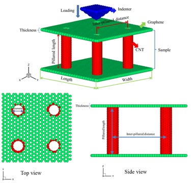
Figure 1. Schematic diagram of 3D-pillared graphene model used in simulation.
Download figure:
Standard image High-resolution imageTable 1. Description of the different simulated pillared graphene with various diameters of the CNTs.
| Type | Diameter (nm) | CNT/graphene thickness (nm) | Pillared length (nm) | Inter-pillared distance (nm) |
|---|---|---|---|---|
| (6,6) | 0.8079 | 0.34 | 1.2 | 2.5 |
| (7,7) | 0.9425 | 0.34 | 1.2 | 2.5 |
| (8,8) | 0.1077 | 0.34 | 1.2 | 2.5 |
| (9,9) | 0.1213 | 0.34 | 1.2 | 2.5 |
| (9,0) | 0.6996 | 0.34 | 1.2 | 2.5 |
| (11,0) | 0.8551 | 0.34 | 1.2 | 2.5 |
| (13,0) | 0.1011 | 0.34 | 1.2 | 2.5 |
| (15,0) | 0.1166 | 0.34 | 1.2 | 2.5 |
In the molecular dynamics simulation, the C–C bonds of 3D-pillared graphene are described using the following Tersoff potential energy functions [20]:


where ζij is a function of many-body potential with bond angle g(θjik) effects and fc(rik) denotes the cutoff function relative to the nearest-neighbour interactions.
The van der Waals interactions between the indenter and the 3D-pillared graphene are described by the Lennard-Jones potential model as follows [21]:
where ε is the binding energy, σ is the distance to the zero in U(rij), and rij is the distance between atoms i and j. The parameters of this Tersoff–Brenner many-body potential function and the Lennard-Jones potential are listed in table 2 [20, 21]. Then, from equation (10), for the deformation method, the nanoindentation deformation mechanism of 3D-pillared graphene can be formulated as follows [22]:
where xij and Xij are the current coordinates (after loading) and reference coordinates (before loading), respectively, and ns is the number of deformed neighbours of atoms. In this study, all numerical solutions were obtained using Gear's fifth-order predictor–corrector algorithm.
Table 2. Parameters for Tersoff and Lennard-Jones potential functions.
| Tersoff potential [20] | A (eV) | 1.3936 × 10³ | β | 1.5724 × 10⁻⁷ |
| B (eV) | 3.467 × 10² | N | 7.2751 × 10⁻¹ | |
| λ1 (Å−1) | 3.4879 | C | 3.8049 × 10⁴ | |
| λ2 (Å−1) | 2.2119 | d | 4.384 × 100 | |
| D (Å) | 0.15 | R (Å) | 1.95 | |
| Lennard-Jones potential [21] | ε (kJ mol−1) | 0.4396 | σ (Å) | 3.851 |
The hardness (H) of 3D-pillared graphene was evaluated in accordance with Oliver [23] and Pharr [24]:

where Pmax and Ac are the maximum indentation load and projected contact area of the indentation, respectively. Ac is evaluated as follows [25]:

where hc is the contact depth with deformation around the indentation. The reduced modulus (Er) of 3D-pillared graphene was evaluated as follows [26]:

where Sc = dP/dh is the slope at the start of the indentation unloading process in the load–displacement curve.
To determine the 3D-pillared graphene strength, general contact stiffness (Sc) formulae were used [27]:

where p and h are the load of the material and the indentation depth, respectively.
3. Results and discussion
3.1. Deformation mechanism under nanoindentation process
Figure 2 shows snapshots of the armchair (9,9) CNTs in the nanoindentation process at 5, 50, 100, and 180 ps at 600 K. The indentation holding process was 20 ps and the indentation velocity was 25 m s−1. The maximum indentation depth was set at 1 nm. The colour indicates the magnitude of the deformation during indentation, and thus the nature of deformation in the 3D-pillared graphene. Figure 2(a) shows the initial position of the indenter. After thermal equilibrium was reached, the indenter approached the substrate, deforming it upwards via van der Waals attractive forces [28], as shown in figure 2(b). When the maximum depth was reached at 100 ps, the deformation of the 3D-pillared graphene increased to approximately 4.26 Å, as shown in figure 2(c). In the holding process, the transfer of interactive force from normal forces to adsorption forces and the adhesion between the indenter and the substrate was expected (figure 2(d)).

Figure 2. Deformation of 3D-pillared graphene during nanoindentation process at (a) 5, (b) 50, (c) 100 (maximum indentation depth) and (d) 180 ps.
Download figure:
Standard image High-resolution image3.2. Mechanical properties and size effect of armchair and zigzag 3D-pillared graphene
Figure 3 shows the loading force as a function of tip displacement for armchair 3D-pillared graphene with (6,6), (7,7), (8,8) and (9,9) CNTs, respectively. The maximum indentation depth and operation temperature were 1 nm and 600 K, respectively. The indentation simulation includes the indenter approaching the 3D-pillared graphene (tip displacement from 0 to 1.5 nm), loading, holding and unloading processes. The indentation force generally increases with increasing armchair CNT diameter and decreases with increasing adhesion force during the loading process. The maximum adhesion forces for armchair (6,6), (7,7), (8,8) and (9,9) CNTs are 0.27 nN, 0.23 nN, 0.22 nN and 0.21 nN, respectively. The lower-left inset shows the deformation distributions for armchair 3D-pillared graphene with (6,6), (7,7), (8,8) and (9,9) CNTs, respectively, at 100 ps (red colour indicates the maximum deformation amount). The CNT diameter increased with decreasing contact area between the graphene sheet and the indenter.
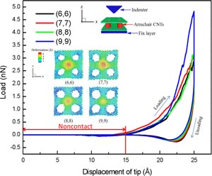
Figure 3. Variation of loading force of armchair 3D-pillared graphene with tip displacement at 600 K and indentation depth of 1.0 nm for (6,6), (7,7), (8,8) and (9,9) CNTs.
Download figure:
Standard image High-resolution imageFigure 4 shows the relationship between the hardness and maximum load of armchair 3D-pillared graphene with (6,6), (7,7), (8,8) and (9,9) CNTs, respectively. The results indicate that the hardness of armchair 3D-pillared graphene is 0.12–0.20 GPa and the maximum loading force of armchair CNTs is 2.91–4.83 nN. The variation of the hardness of the armchair 3D-pillared graphene structure is mainly affected by the combination of the graphene sheet and CNTs. Here, the hardness and the indentation force increase with increasing CNT diameter. A maximum increase in hardness of approximately 40% was observed for the armchair 3D-pillared graphene in this study.

Figure 4. Variation of hardness and maximum load of armchair 3D-pillared graphene with CNT type.
Download figure:
Standard image High-resolution imageFigure 5 shows the relationship between the reduced modulus and dissipation energy of armchair 3D-pillared graphene with (6,6), (7,7), (8,8) and (9,9) CNTs, respectively. It can be seen that the reduced modulus of armchair 3D-pillared graphene is 0.83–1.01 TPa. Additionally, the reduced modulus increases with increasing CNT diameter during the indentation process, which shows that an increase in CNT diameter helps energy relaxation of material. The dissipation energy increased when the diameter of the CNTs of armchair 3D-pillared graphene decreased for a given indentation depth.

Figure 5. Variation of reduced modulus and dissipation energy of armchair 3D-pillared graphene with (6,6), (7,7), (8,8) and (9,9) CNTs, respectively.
Download figure:
Standard image High-resolution imageFigure 6 shows the loading force as a function of tip displacement for zigzag 3D-pillared graphene with (9,0), (11,0), (13,0) and (15,0) CNTs, respectively, at a temperature of 600 K and an indentation depth of 1.0 nm. The indentation simulation includes the indenter approaching the 3D-pillared graphene (tip displacement from 0 to 1.5 nm), loading, holding and unloading processes. The loading force decreases with increasing carbon zigzag 3D-pillared graphene nanotube diameter because the structural strength in the indentation direction is reduced. The lower-left inset shows that when the CNT diameter increases, the contact area between the graphene sheet and the tip decreases. The indentation force generally decreases with increasing zigzag CNT diameter and increases with increasing adhesion force during the loading process. The maximum adhesion forces for zigzag 3D-pillared graphene with (9,0), (11,0), (13,0) and (15,0) CNTs are 0.17 nN, 0.24 nN, 0.25 nN and 0.18 nN, respectively.

Figure 6. Variation of loading force of zigzag 3D-pillared graphene with tip displacement at 600 K, and indentation depth of 1.0 nm for (9,0), (11,0),(13,0) and (15,0) CNTs.
Download figure:
Standard image High-resolution imageFigure 7 shows the relationship between the hardness and maximum load for zigzag 3D-pillared graphene with (9,0), (11,0), (13,0) and (15,0) CNTs, respectively. The decrease in the hardness and maximum load with diameter is almost linear. The hardness values are 0.20 GPa, 0.18 GPa, 0.17 GPa and 0.13 GPa and the maximum loads are 4.87 nN, 4.43 nN, 4.22 nN and 3.19 nN for (9,0), (11,0), (13,0) and (15,0) CNTs, respectively. The hardness value of the (15,0) CNT is more than 34% lower than that of the (9,0) CNT, so the CNTs of zigzag 3D-pillared graphene structure are stronger in smaller CNT diameter.

Figure 7. Variation of hardness and maximum load of zigzag 3D-pillared graphene with CNT type.
Download figure:
Standard image High-resolution imageFigure 8 shows the relationship between the reduced modulus and dissipation energy of zigzag 3D-pillared graphene with (9,0), (11,0), (13,0) and (15,0) CNTs, respectively. The reduced modulus decreases with increasing CNT diameter of zigzag 3D-pillared graphene and it was found that a recession value of 54.5% was reached for the reduced modulus (compared with the (9,0), and (15,0) CNTs). The dissipation energy of zigzag 3D-pillared graphene linearly decreases with increasing CNT diameter. The dissipation energy values for zigzag 3D-pillared graphene with (9,0), (11,0), (13,0) and (15,0) CNTs are 16.1 × 10⁻¹⁷ J, 10.7 × 10⁻¹⁷ J, 10.5 × 10⁻¹⁷ J and 9.7 × 10⁻¹⁷ J, respectively. These results are due to the dissipation energy of zigzag 3D-pillared graphene increasing with decreasing deformation capacity of zigzag 3D-pillared graphene.
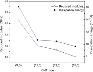
Figure 8. Variation of reduced modulus and dissipation energy of zigzag 3D-pillared graphene with (9,0), (11,0), (13,0) and (15,0) CNTs, respectively.
Download figure:
Standard image High-resolution image3.3. Effect of temperature
The loading force of zigzag 3D-pillared graphene versus tip displacement for various temperatures is shown in figure 9. The indentation simulation includes the indenter approaching the 3D-pillared graphene (tip displacement from 0 to 1.5 nm), loading, holding and unloading processes. As the reaction temperature increases, the kinetic energy of the substrate increases. The lower-left inset shows the deformation, which increases linearly with temperature. However, the maximum load of zigzag 3D-pillared graphene decreases with temperature, with values of 3.49 nN, 3.38 nN, 2.91 nN and 2.85 nN for temperatures of 400 K, 500 K, 600 K and 700 K, respectively. This may be caused by the thermal shock of atom–atom interactions with an increase in the substrate temperature. Figure 10 shows the hardness and maximum load of zigzag 3D-pillared graphene at 400, 500, 600 and 700 K. The hardness decreases with increasing zigzag 3D-pillared graphene temperature, with values of 0.14 nN, 0.13 nN, 0.12 nN and 0.11 nN for temperatures of 400 K, 500 K, 600 K and 700 K, respectively. This is probably due to the increase in the atomic mobility at higher temperatures during the nanoindentation process. When the temperature of the substrate was increased, the maximum load decreased. This may be explained by the increased deformation ability of the tip–substrate interface with increasing temperature.

Figure 9. Variation of load force of zigzag 3D-pillared graphene with tip displacement at 400, 500, 600 and 700 K, (indentation depth was set at 1.0 nm).
Download figure:
Standard image High-resolution image
Figure 10. Variation of hardness and maximum load of zigzag 3D-pillared graphene with temperature.
Download figure:
Standard image High-resolution imageFigure 11 shows the relationship between the reduced modulus and dissipation energy of zigzag 3D-pillared graphene at 400 K, 500 K, 600 K and 700 K, respectively. The dissipation energy decreases with increasing temperature due to the atoms becoming more active and having better shift ability at higher temperatures. Therefore, the area of force–displacement curve is smaller at a higher temperature [29, 30].
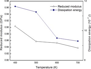
Figure 11. Variation of reduced modulus and dissipation energy of zigzag 3D-pillared graphene with temperature.
Download figure:
Standard image High-resolution image3.4. Comparison of 3D-pillared graphene with different types of nanotube
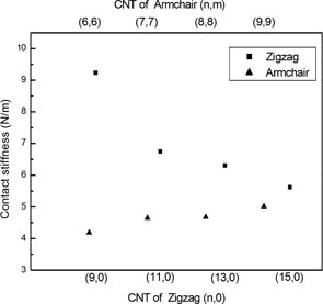
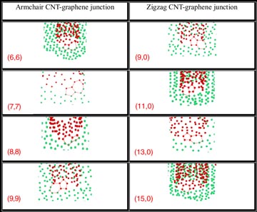
Figure 12 shows the effect of contact stiffness of different types of nanotube with armchair and zigzag-pillared graphene. The contact stiffness for the structure consisting of (9,9) armchair-pillared graphene is generally higher than that of the structure consisting of (6,6) armchair-pillared graphene. The contact stiffness of the zigzag-pillared graphene with (9,0) CNTs is higher than those of the zigzag-pillared graphene with (11,0) and (13,0) CNTs. These results indicate that the contact stiffness increases (decreases) with increasing diameter of armchair (zigzag)-pillared graphene. These results are in agreement with previous results that showed that zigzag-pillared graphene with CNTs has a larger contact stiffness than that of armchair-pillared graphene with CNTs due to its geometry of atomic structures [31]. The structures of CNT–graphene junctions with plastic deformation (5–7–5 rings) are listed in table 3. It can be seen that all CNT types were covalently bonded to the graphene plane [11, 32].
Figure 12. Variation of contact stiffness with CNT type for armchair and zigzag-pillared graphene.
Download figure:
Standard image High-resolution image
Table 3. The plastic deformation of CNT–graphene junction with 5–7–5 rings for various types of CNTs.
 |
4. Conclusion
In this study, the mechanical properties of 3D-pillared graphene nanostructures were examined using nanoindentation simulations. The following main conclusions were obtained.
- (1)For armchair-pillared graphene, an increase in CNT diameter increases the contact stiffness and loading force during the nanoindentation process.
- (2)For zigzag-pillared graphene, an increase in CNT diameter decreases the contact stiffness due to an increase in axial compression.
- (3)The maximum loading force of zigzag-pillared graphene (4.87 nN) is higher than that of armchair-pillared graphene (4.83 nN).
- (4)Zigzag-pillared graphene had the best mechanical properties under the nanoindentation proces
Acknowledgments
This work was supported by the Ministry of Science and Technology of Taiwan under grants MOST 100-2628-E-151-003-MY3 and MOST 103-2811-E-151-001.