
Abstract
The ability to generate a permanent, stable magnetic field unsupported by an electromotive force is fundamental to a variety of engineering applications. Bulk high temperature superconducting (HTS) materials can trap magnetic fields of magnitude over ten times higher than the maximum field produced by conventional magnets, which is limited practically to rather less than 2 T. In this paper, two large c-axis oriented, single-grain YBCO and GdBCO bulk superconductors are magnetized by the pulsed field magnetization (PFM) technique at temperatures of 40 and 65 K and the characteristics of the resulting trapped field profile are investigated with a view of magnetizing such samples as trapped field magnets (TFMs) in situ inside a trapped flux-type superconducting electric machine. A comparison is made between the temperatures at which the pulsed magnetic field is applied and the results have strong implications for the optimum operating temperature for TFMs in trapped flux-type superconducting electric machines. The effects of inhomogeneities, which occur during the growth process of single-grain bulk superconductors, on the trapped field and maximum temperature rise in the sample are modelled numerically using a 3D finite-element model based on the H-formulation and implemented in Comsol Multiphysics 4.3a. The results agree qualitatively with the observed experimental results, in that inhomogeneities act to distort the trapped field profile and reduce the magnitude of the trapped field due to localized heating within the sample and preferential movement and pinning of flux lines around the growth section regions (GSRs) and growth sector boundaries (GSBs), respectively. The modelling framework will allow further investigation of various inhomogeneities that arise during the processing of (RE)BCO bulk superconductors, including inhomogeneous Jc distributions and the presence of current-limiting grain boundaries and cracks, and it can be used to assist optimization of processing and PFM techniques for practical bulk superconductor applications.
Export citation and abstract BibTeX RIS
1. Introduction
The ability to generate a permanent, stable magnetic field unsupported by an electromotive force is fundamental to a variety of engineering applications. The magnetization of conventional permanent magnets, such as NdFeB and SmCo, which is a useful measure of the ability to generate magnetic fields, is independent of sample volume and is therefore limited by the material properties of the permanent magnet (i.e., it cannot be increased by subtle changes to processing). Bulk high temperature superconducting (HTS) materials, on the other hand, trap magnetic flux via the generation of macroscopic electrical currents, which leads directly to an increase in magnetization with sample volume. This, in turn, potentially overcomes this fundamental limit in the size of field generated by conventional permanent magnets.
The peak trapped magnetic flux density, Btrap, at the centre of a (RE)BCO (where RE = a rare earth element or yttrium) single-grain bulk superconductor, oriented with its thickness parallel to the c-axis, due to an induced, persistent supercurrent is given in its simplest form by

where A is a geometrical constant, μ0 is the permeability of free space, Jc is the critical current density of the superconducting material and d is the sample diameter. This implies two main approaches for improving the field-trapping ability of a bulk superconductor: (1) by enhancing the critical current density through improved flux pinning and increased sample homogeneity, and (2) by increasing the sample size.
Bulk superconductors can trap magnetic fields of magnitude over ten times higher than the maximum field produced by conventional magnets, which is limited practically to rather less than 2 T. Indeed, the world record field generated by an arrangement of two bulk superconductors currently stands at 17 T at 29 K [1]. Bulk superconductors can exhibit Jcs of 5 × 10⁴ A cm−2 at 1 T and 77 K (the boiling point of liquid nitrogen), resulting typically in trapped fields of up to between 1 and 1.5 T for YBCO and greater than 2 T for (RE)BCO at this technologically important temperature, with the highest trapped field at 77 K currently standing at 3 T [2]. As a result, there is great interest in using these materials as trapped field magnets (TFMs) in a number of engineering applications, including magnetic levitation, magnetic bearings, energy storage flywheels, magnetic resonance imaging, magnetic separation and rotating machines [3]. Significantly, the higher magnetic loading in rotating machines would provide an increased torque/power density, resulting potentially in a machine that is smaller and lighter in weight than conventional devices of the same rating [4]. However, developing a practical magnetizing technique is crucial to using bulk superconductors as TFMs in applications of these types.
There are three magnetization techniques for magnetizing a bulk superconductor that are in common use: zero field cooling (ZFC), field cooling (FC) and pulse field magnetization (PFM). In ZFC, the superconductor is cooled below its critical temperature, Tc, prior to the application of a large magnetic field, typically of several Teslas. A magnetic field of comparatively lower magnitude is applied in the FC process to a superconductor at a temperature above Tc, which is then cooled below Tc. In either case, to trap the maximum possible field corresponding to the sample's flux-trapping ability, the magnitude of the applied field needs to be at least Btrap (at least Btrap in FC; 2Btrap in ZFC), assuming Bean's model [5, 6]. This invariably requires large magnetizing coils, which is impractical for most applications of these materials. The PFM technique is similar to ZFC, except that the large magnetic field is applied via a pulse on the order of milliseconds, rather than ramped up and down slowly over a period of many minutes or even hours. Achieving reliable, in situ magnetization is crucial to producing a competitive and compact machine design in trapped flux-type rotating machines, and the PFM technique shows great promise as a compact, mobile and relatively inexpensive magnetization technique for the magnetization of such devices. However, one issue with this technique is that the trapped field produced using PFM is much smaller than that of ZFC or FC, due to the large temperature rise ΔT associated with the rapid dynamic movement of the magnetic flux in the interior of the superconductor during the PFM process [7]. Compared with the record trapped field (17 T at 29 K), which was generated by a field-cooled technique, the record trapped field produced by PFM is only 5.2 T at 29 K [8]. Therefore, it is important to understand the flux dynamics when magnetizing a bulk superconductor using the PFM technique in order to achieve an optimum trapped field profile and to investigate how these results translate into a practical magnetizing technique for a trapped flux-type superconducting electric machine.
In this paper, we investigate the magnetization of two, large c-axis oriented single-grain Y–Ba–Cu–O (YBCO) and Gd–Ba–Cu–O (GdBCO) bulk superconductors by the PFM technique at temperatures of 40 and 65 K. We report the characteristics of the trapped field produced by this technique with a view to developing a practical in situ magnetizing process for TFMs in trapped flux-type superconducting electric machines.
2. Bulk superconductor sample details
The pulsed field magnetization of the YBCO and GdBCO single-grain superconducting samples shown in figure 1 has been investigated as part of this study. The YBCO sample has a diameter of 32 mm and thickness 15 mm. The GdBCO sample, which contains 10 wt% Ag2O, has a diameter of 41 mm and thickness 16 mm. Both samples were fabricated by the top-seeded melt-growth (TSMG) method, similar to that described in previous research [9]. Precursor powders for fabrication of the GdBCO sample with a composition 75 wt% Gd-123 + 25 wt% Gd-211 + 10 wt% Ag2O + 1.0 wt% BaO2 + 0.1 wt% Pt were mixed and ground thoroughly using an electrical mortar and pestle. 190 g of this mixed powder was pressed uniaxially into pellets 50 mm in diameter and placed on ZrO2 rods inside a box furnace. A generic seed of composition 1 wt% MgO–NdBCO [9] was placed on the top surface of the pressed pellet to control both nucleation and grain orientation. The sample was heated to 1045 °C, held for 1 h, then cooled appropriately through its peritectic growth window, until finally being furnace cooled to room temperature. The as-grown single grain was then oxygenated in a tube furnace at temperatures between 360 and 440 °C for 300 h. The YBCO sample was fabricated using a similar process, but with the key processing temperatures varied accordingly for this system. The samples were mounted on a sample holder fabricated from 316 stainless steel of inner diameter 46 mm and outer diameter 56 mm to match the dimensions of the available cold stage of the pulse system. Stycast 2850 FT, Catalyst 23 LV was used to mount the samples in the holder, with the epoxy set under vacuum to ensure void-free embedment.

Figure 1. YBCO (left) and GdBCO (right) bulk superconductor samples. The growth sector boundaries (GSBs) are shown in each sample.
Download figure:
Standard image High-resolution imageThe trapped field distributions at 77 K obtained by field cooling for each sample are shown in figure 2. This resulted in peak trapped fields at the centre of the top surface of each sample of 0.692 T (YBCO) and 1.19 T (GdBCO).
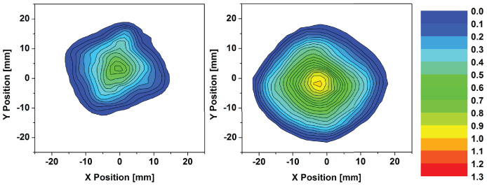
Figure 2. Trapped field distribution at 77 K obtained by field cooling (FC) for each bulk superconductor: YBCO (left), GdBCO (right). The peak trapped field at the centre of the top surface of each sample was 0.692 T and 1.19 T, respectively.
Download figure:
Standard image High-resolution imageFigure 3 shows the magnitude of trapped field obtained by FC for each bulk sample as a function of temperature, in which the vertical axis shows the normalized trapped field divided by the sample diameter d, measured by a Hall sensor located at the centre of the top surface of the bulk samples. This normalization accounts for the difference in sample sizes and can be considered an average critical current density for each sample, averaged over the sample volume and including the field-dependent nature of the critical current density [10].
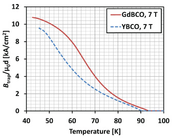
Figure 3. Trapped field normalized to units of kA cm−2 obtained by FC for the GdBCO and YBCO bulk samples investigated in this study as the temperature is increased from 40 to 100 K for an applied field of 7 T. The value of the vertical axis represents the pinning strength as the average critical current density of each sample.
Download figure:
Standard image High-resolution imageAfter initially magnetizing the sample at around 40 K by FC with an applied field of 7 T, the temperature was increased slowly to 100 K at a rate of 0.3 K min−1. The peak trapped field at the centre of the bulk at 46 K was 5.5 T for GdBCO bulk and 4.8 T for YBCO. After correcting the data for the difference in size of the bulk samples (the GdBCO is 41 mm and the YBCO is 32 mm), it is clear from this figure that pinning in the GdBCO sample is significantly stronger than that in the YBCO sample investigated in this study.
3. Pulsed field magnetization experimental results
An overview of the pulsed field magnetization experimental arrangement is shown in figure 4. The bulk samples were mounted tightly on the cold stage of a Gifford–McMahon (GM), closed cycle helium refrigerator, and a copper magnetizing solenoid pulse coil, cooled using liquid nitrogen, was placed outside the vacuum chamber. This magnetizing coil generates pulsed fields up to Bapp = 6.4 T with a rise time of tr = 12 ms and duration of approximately td = 120 ms. The typical characteristics of the applied pulsed fields are shown in figure 5. The time dependence of the externally applied pulsed field Bext(t) was monitored by the current i(t) flowing in a shunt resistor connected in series with the pulse coil. The central axis of the applied field coincides with that of the bulk, such that the direction of the applied field is perpendicular to the top surface of the samples.
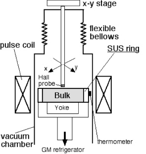
Figure 4. Schematic illustration of the pulsed field magnetization experimental arrangement.
Download figure:
Standard image High-resolution image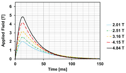
Figure 5. Typical applied pulsed field characteristics. These fields were applied to the YBCO sample at 65 K.
Download figure:
Standard image High-resolution imageDifferent amplitudes of pulsed fields of up to 6.3 T were applied to each sample and the two-dimensional trapped field distributions were measured inside the vacuum chamber using an x−y stage controller and an axial-type Hall sensor positioned 1 mm above the top surface of each sample. The applied field and the trapped field close to the centre of the sample were measured dynamically during the application of each pulse using the same Hall sensor (located on the top surface of the samples).
Figure 6 shows the typical evolution of the trapped field with time, measured close to the centre of the sample using a Hall sensor located on the top surface of the samples. These results are derived from measurements of the YBCO sample at 65 K for the applied pulsed fields shown in figure 5. The value at t = 300 ms, after allowing for adequate relaxation of the magnetic flux, is referred to hereafter as Btrap, the trapped field at the centre of the top surface of the sample.
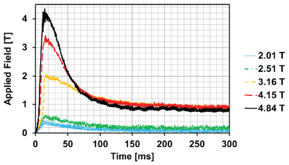
Figure 6. Typical evolution of the trapped field with time measured close to the centre of the sample using a Hall sensor located on the top surface of the samples. These results are from measurements of the YBCO sample at 65 K for the applied pulsed fields shown in figure 5.
Download figure:
Standard image High-resolution imageTwo-dimensional trapped field distributions measured at 1 mm above the top surface of the YBCO sample at 65 K and 40 K are shown in figures 7 and 8, respectively. Figures 9 and 10 show the trapped field distributions for the GdBCO sample at 65 K and 40 K, respectively. The central panels of figures 7–10 show the maximum trapped field for fully magnetized samples and the trapped field close to the centre of the sample for cases where the sample was not fully magnetized.
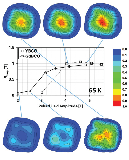
Figure 7. Trapped field distributions measured at 1 mm above the top surface of the YBCO sample at 65 K. The central panel shows the maximum trapped field for fully magnetized samples and the trapped field close to the centre of the sample prior to full magnetization.
Download figure:
Standard image High-resolution image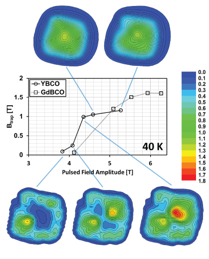
Figure 8. Trapped field distributions measured at 1 mm above the top surface of the YBCO sample at 40 K. The central panel shows the maximum trapped field for fully magnetized samples and the trapped field close to the centre of the sample prior to full magnetization.
Download figure:
Standard image High-resolution image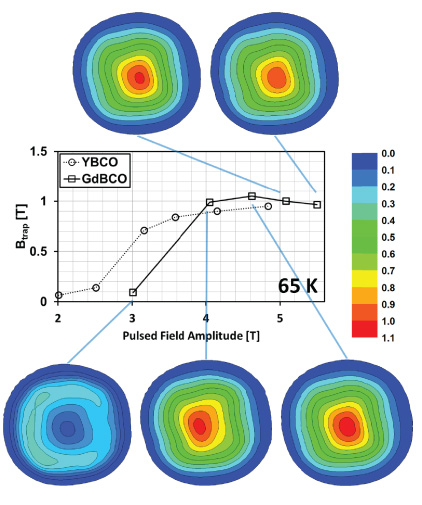
Figure 9. Trapped field distributions measured at 1 mm above the top surface of the GdBCO sample at 65 K. The central panel shows the maximum trapped field for fully magnetized samples and the trapped field close to the centre of the sample prior to full magnetization.
Download figure:
Standard image High-resolution image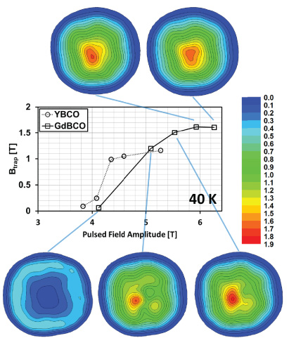
Figure 10. Trapped field distributions measured at 1 mm above the top surface of the GdBCO sample at 40 K. The central panel shows the maximum trapped field for fully magnetized samples and the trapped field close to the centre of the sample prior to full magnetization.
Download figure:
Standard image High-resolution imageFigures 7 and 8 show that the YBCO sample becomes magnetized initially along the growth sector boundaries (GSBs), which are highlighted for reference in figure 1. Of the four GSBs, two in particular exhibit preferential pinning along their length. Once the magnitude of the applied pulsed field is sufficiently high that it magnetizes the sample fully, the trapped field distribution changes to a characteristic, approximately conically-shaped trapped field. The field required to fully magnetize the bulk sample will be hereafter referred to as the 'activation field' (for example, the activation field in figure 7 is around 3.4 T). There is no significant increase in trapped field for larger applied fields than the activation field, and, in fact, the trapped field begins to reduce for a sufficiently large field due to the temperature rise in the bulk generated by the rapid movement of flux lines in the sample interior [11].
Cooling the sample to a lower temperature (e.g., from 65 to 40 K) results in stronger flux pinning and a higher Jc within the sample, which results in much higher localized field densities (the behaviour seen in the trapped field distribution is qualitatively the same). However, the maximum trapped field is not increased significantly at 40 K, which differs from the slower ZFC and FC techniques (see figure 3). With respect to the magnetization of bulk superconductors in a trapped flux-type superconducting machine, the choice of temperature range is crucial, and for PFM, it is clear from these results that it is not necessarily true that a lower temperature results in a significantly higher trapped field as observed for the ZFC/FC techniques. The lower specific heat and stronger pinning forces at lower temperatures result in a larger amount of heat generated in the sample, which suppresses Jc and hence trapped field. As a result, these data show that sample performance in terms of trapped field is not improved significantly at 40 K compared to that at 65 K. The activation field for the YBCO sample is higher at 40 K (4.6 T at 40 K compared with 3.6 T at 65 K), although the resulting trapped field is only marginally bigger. This would justify, for example, the selection of a machine operating temperature range of 65–77 K, simplifying the cryogenics without compromising significantly on material performance. An additional consideration, and an argument for higher operating temperature, is that stronger pinning at lower temperatures (or between different samples, as described below) results in a higher activation field that would require a larger and more complex magnetizing assembly.
The trapped field distributions for the GdBCO sample are shown in figures 9 and 10. The results indicate a much more homogeneous sample in comparison to YBCO, which is particularly obvious for fields below the activation field. The bulk, single-grain sample should be as homogeneous as possible to enhance the trapped field produced by the PFM technique. If large inhomogeneities, such as those present in the YBCO sample, exist within the bulk between the GSBs and growth sector regions (GSRs), the trapped field profile becomes inhomogeneous, particularly for fields below the activation field. In addition, the magnetization profile of the trapped field is not necessarily enhanced, even though the trapped field generated by ZFC/FC techniques may be maximized in the same samples. It is also clear from these results that the flux pinning strength is greater for the GdBCO sample, which results in a higher trapped field, but also in a larger magnetizing device for an electric machine design due to the higher activation field, as described above.
4. Modelling inhomogeneous behaviour
In this section, the influence of inhomogeneities on trapped field is investigated qualitatively using a three-dimensional (3D) finite-element model. The finite-element model is based on the H-formulation, which has been applied variously to analysing high temperature superconductors for over a decade [12–22], and is implemented using COMSOL Multiphysics 4.3a [23]. To model the electromagnetic and thermal properties of a bulk superconductor in 3D, we have extended previous models of HTS coated conductors [17–19, 21] and drawn additional inspiration from references [20, 24, 25].
Inhomogeneities occur during the growth process of c-axis seeded, single-grain (RE)BCO bulk superconductors, resulting in the formation of GSBs and GSRs described above and shown in figure 1, with a higher critical current density for the GSBs in comparison with the GSRs [26–29]. Here the trapped field distribution and maximum temperature rise for an applied pulsed magnetic field is compared for a completely homogeneous bulk superconducting sample with an ab-plane Jc of 1 × 10⁸ A m−2 and an inhomogeneous sample with the same average Jc, but with Jc varying as a cosine function in the ab-plane [20], as shown in figure 11. The thick, dashed lines represent the GSBs. Other than this spatial variation of Jc, a constant Jc approximation is considered for the in-field behaviour for the purposes of this analysis. The superconductor is modelled using an E−J power law relation [30, 31], EαJn, where n = 21. An external pulsed magnetic field is applied to the bulk along the z-axis, perpendicular to the top surface of the sample, by setting appropriate boundary conditions such that

where τ = 12 ms. This waveform approximates the typical experimentally applied pulsed fields shown previously in figure 5, with a rise time of 12 ms and a pulse width of approximately 120 ms for;
- (1)A homogeneous bulk sample with an average Jc of 1 × 10⁸ A m−2.
- (2)An inhomogeneous bulk sample with a Jc of 1 × 10⁸ A m−2 with x−y spatial variation ± 0.1 × 10⁸ A m−2.

Figure 11. Spatial distribution of the critical current density Jc(θ) in the ab-plane (xy-plane) of the bulk superconductor for the two cases being analysed (homogeneous and inhomogeneous).
Download figure:
Standard image High-resolution imageIn order to simulate the thermal effects of an external field on trapped field, a thermally-isolated model of a bulk superconductor is used. The simulation is carried out using the COMSOL Heat Transfer module, coupled with the H-formulation, which uses the general partial differential equation (PDE) module. The HTS bulk sample is assumed to be cooled by liquid nitrogen, with the sample environment described by the thermal model parameters listed in table 1, which are typical for these (RE)BCO bulk superconductors [24].
Table 1. Thermal model parameters.
| Parameter | Description | Value |
|---|---|---|
| Tc | Transition temperature | 92 K |
| ρb | HTS bulk density | 5.9 × 10³ kg m−3 |
| ρn | Nitrogen density | 808.4 kg m−3 |
| Cb | Heat capacity of bulk | 1.32 × 10² J kg−1 K−1 |
| Cn | Heat capacity of liquid nitrogen at 77 K | 1040 J K−1 kg−1 |
| kab | Thermal conductivity of bulk along ab-plane | 20 W m−1 K−1 |
| kc | Thermal conductivity of bulk along c-axis | 4 W m−1 K−1 |
| kn | Thermal conductivity of liquid nitrogen | 0.026 W m−1 K−1 |
| E0 | Characteristic voltage | 1 × 10⁻⁴ V m−1 |
| α | Critical current density extrapolated to T = 0 K | 6.1 × 10⁸ A m−2 |
| τ | Rise time of applied magnetic field | 12 ms |
| Bapp | Peak value of applied magnetic field | 0–5 T |
The following thermal transient equation is used in this model:

Jc0 (T) is the temperature-dependent critical current density of the superconductor, given by:
where α is the critical current density extrapolated to T = 0 K. The heat source Q in the thermal model is derived from the product of the electric field and current density throughout the bulk superconductor, defined as Q = Enorm ⋅ Jnorm, where  and
and  .
.
The maximum trapped field at the centre of the top surface for the homogeneous and inhomogeneous Jc distribution models are compared in figure 12. Pulsed fields of between 0 and 5 T are applied to the bulk sample at 77 K. Similar to the experimental results shown in the central panels of figures 7–10, there is an optimal activation field, above which the trapped field reduces with increasing field magnitude due the temperature rise associated with the movement of flux lines. Figure 13 shows the two-dimensional trapped field distributions at the top surface of the bulk for a range of applied fields (Bapp = 1, 3 and 5 T) at time t = 300 ms, which gives the flux some time to relax after the pulse is applied. The inhomogeneous distribution of pinning sites results in a distorted trapped field profile, where flux is trapped preferentially in regions of stronger pinning (higher Jc). Although flux enters the superconductor more easily via the GSRs due to weaker pinning (lower Jc), it also leaves this region more easily and this results in localized heating acting to reduce Jc/pinning strength further.

Figure 12. Maximum trapped field at the centre of the top surface, as well as the maximum temperature rise in the superconductor, for the homogeneous and inhomogeneous Jc distribution models. Pulsed fields of between 0 and 5 T are applied to the bulk samples at 77 K.
Download figure:
Standard image High-resolution image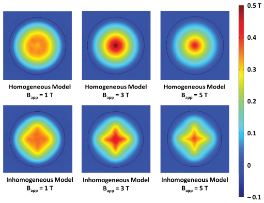
Figure 13. Trapped field distributions for the homogeneous and inhomogeneous Jc distribution models for pulsed fields Bapp = 1, 3 and 5 T at time t = 300 ms, allowing flux to relax after the pulse is applied.
Download figure:
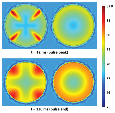
Standard image High-resolution imageFigure 12 also shows the maximum temperature rise in the superconductor for each model for the same applied field pulse. The inhomogeneous model produces a larger maximum temperature rise, which results in a lower trapped field. The inhomogeneous distribution of pinning centres acts to reduce the maximum trapped field potential of the sample as described above. Finally, figure 14 compares the temperature distributions generated by the homogeneous (right) and inhomogeneous (left) models at the pulse peak (t = 12 ms) and pulse end (t = 120 ms) for an intermediate applied pulsed magnetic field Bapp = 3 T. There are contributions to the heat generated in the bulk superconductor from magnetic flux moving into (t ≤ 12 ms) and out of (t > 12 ms) the sample.
Figure 14. Comparison of the temperature distributions generated by the homogeneous (right) and inhomogeneous (left) models at the pulse peak (t = 12 ms) and pulse end (t = 120 ms) for an applied pulsed magnetic field Bapp = 3 T. There are contributions to the heat generated in the bulk superconductor from magnetic flux moving into (t ≤ 12 ms) and out of (t > 12 ms) the sample.
Download figure:
Standard image High-resolution image
This modelling framework allows the presence of the various inhomogeneities that arise during the processing of (RE)BCO bulk superconductors to be considered, including inhomogeneous Jc distributions (between top and bottom regions or between the seed and outer edge of the bulk [32, 33], for example) and the presence of current-limiting grain boundaries and cracks. It can be used to assist optimization of processing techniques, such as samples with novel seed arrangements [34–37], as well as PFM techniques and pulse coil design, for practical bulk superconductor applications.
5. Conclusion
In this paper, two large c-axis oriented, single-grain YBCO and GdBCO bulk superconductors were magnetized by the pulsed field magnetization (PFM) technique at temperatures of 40 and 65 K and the characteristics of the resulting trapped field were investigated with a view of magnetizing such samples as trapped field magnets (TFMs) in situ inside a trapped flux-type superconducting electric machine.
Inhomogeneities within the bulk affect the dynamics of the flux entering the sample, causing a distorted trapped field profile with flux trapped preferentially in regions of stronger pinning (higher Jc). It was found by comparing the YBCO and GdBCO samples that the latter has stronger flux pinning, in addition to a more homogeneous distribution of pinning sites, resulting in an enhanced trapped field capability.
It is apparent by comparing the temperature at which the pulsed magnetic field is applied that a lower magnetizing temperature does not necessarily result in much higher trapped field for PFM, and this has implications for the optimum operating temperature for TFMs in trapped flux-type superconducting electric machines. The magnitude of trapped field increases with reducing temperature for slower zero field cooling (ZFC) and field cooling (FC) magnetizing techniques, which require large magnetizing fixtures and timescales. However, there is no such simple relationship for PFM due to the reduced specific heat of the material at lower temperature and the somewhat complex dynamics of the flux movement, which generates heat.
The effects of inhomogeneities, which occur during the growth process of single-grain bulk superconductors, on the trapped field and maximum temperature rise in the sample were modelled numerically using a 3D finite-element model based on the H-formulation and implemented in Comsol Multiphysics 4.3a. The results agree qualitatively with the observed experimental results, in that inhomogeneities act to distort the trapped field profile and reduce the magnitude of the trapped field due to localized heating within the sample and preferential movement and pinning of flux lines around the growth section regions (GSRs) and growth sector boundaries (GSBs), respectively. The modelling framework will allow further investigation of various inhomogeneities that arise during the processing of (RE)BCO bulk superconductors, including inhomogeneous Jc distributions and the presence of current-limiting grain boundaries and cracks, and it can be used to assist optimization of processing and PFM techniques for practical bulk superconductor applications.
Acknowledgments
Dr Mark Ainslie would like to acknowledge the support of a Royal Academy of Engineering Research Fellowship. This research was also supported in part by a Grant-in-Aid for Scientific Research (No. 23560002) from the Ministry of Education, Culture, Sports, Science and Technology, Japan, and an IET Travel Award from the Institution of Engineering and Technology, UK.