
Abstract
This paper investigates the influence of the electromechanical coupling effect on the performances of a hybrid piezoelectric and electromagnetic energy harvester. For a common hybrid energy harvester, we derive an accurate analytical solution and get expressions for the resonant frequency shift, output power, amplitude and conversion efficiency. Then, based on various degrees of coupling effect, the performance of the harvester is studied with different load and excitation frequency, and compared with piezoelectric-only and electromagnetic-only energy harvesters. The results show that the bigger the coupling coefficient, the greater the resonant frequency shift, output power and conversion efficiency. In the weak coupling and medium coupling, the performances of the hybrid energy harvester are better than those of the two separate energy harvesting techniques; however, the hybrid energy harvester does not increase the power and conversion efficiency in contrast with the piezoelectric-only and electromagnetic-only energy harvester in strong coupling. In addition, the optimal load resistance of the hybrid energy harvester is related to the strength of the coupling effect; moreover, the optimal load resistance of the electromagnetic harvesting element for the hybrid harvester is bigger than that of the electromagnetic-only harvester in the medium and strong coupling. Through analysis of the results, ways of boosting the performances of the hybrid energy harvester are found.
Export citation and abstract BibTeX RIS
1. Introduction
Since wireless sensor networks and low power devices have experienced remarkable growth in recent years, this raises the possibility of harvesting energy of the environment to replace the chemical batteries that currently raise maintenance, environment and size issues [1–3]. Therefore, research has recently been focussed on harvesting mechanical energy, especially on converting vibration energy into electric energy, and three mechanisms have been proposed: piezoelectric, electromagnetic and electrostatic [4, 5]. Electrostatic energy harvesters are based on a capacitance mechanism and need an external voltage source to begin harvesting normally, so they cannot work independently. Piezoelectric and electromagnetic energy harvesters have received much more attention as they have high electromechanical coupling and no external voltage source requirement; furthermore, they are particularly attractive for use in MEMS [6]. In recent years, much work has been done on piezoelectric and electromagnetic energy harvesters—for example, their structure design and fabrication by MEMS or the conversion process [7–10], mathematical modeling [11–14], power optimization [15–17] and energy storage and circuit management [18, 19].
At the same time, for piezoelectric or electromagnetic energy harvesters, the effect of electromechanical coupling on the performance of the harvester has been studied and some conclusions have been given. Tang and Yang studied the magnitude and output power of the piezoelectric harvester with various degrees of electromechanical coupling, and concluded that for weak coupling, an SCE (synchronized charge extraction) technique can significantly improve the performance, while for strong coupling, the SCE technique dramatically undermines the performance of the piezoelectric energy harvester [20]. Shu and Lien proposed that the optimization criteria of piezoelectric energy harvesters are different but dependent on the relative strength of the coupling, and for a strong coupling system, the optimal power transfer is not simultaneous with maximum efficiency [21]. Challa et al investigated the effect of coupling strength on the performance of the electromagnetic energy harvester, and it is shown that, up to a certain point, increasing the coupling strength of the harvester substantially increases the output power, resulting in improved device efficiency [22].
However, from the results studied in existing references, although the voltage of the piezoelectric energy harvester can be up to several or tens of volts, the output current is only a few microamperes because of the large internal resistance. On the other hand, the electromagnetic energy harvest can output hundreds or thousands of microamperes, but its voltage is too small to meet the needs of the devices. Therefore, the disadvantages for the two kinds of energy harvesters seriously limit the application ranges, and researchers have proposed that a hybrid energy harvester that combines piezoelectric and electromagnetic harvesting mechanisms can solve these problems simultaneously, and can benefit from the advantages of the two techniques [23, 24].
Much of the literature on energy harvesting has focused on single-type energy harvesters, i.e. piezoelectric or electromagnetic harvesters. But for the hybrid energy harvester, the research works are relatively few, and also mainly focus on the structural design and performance validation, in contrast with the single harvesting mechanism harvesters. Wacharasindhu and Wkwon designed a MEMS energy harvester that combined electromagnetic and piezoelectric conversion, and the experimental results showed that the maximum harvested power is about 40.8 μW with a 3 MΩ load from piezoelectric conversion and 1.15 μW with a 35 Ω load from electromagnetic conversion [25]. Challa et al designed a coupling piezoelectric–electromagnetic meso-harvester based on a moving magnetic type, and researched the total power through experimental tests, whose results demonstrated a 30% increase in power output in comparison to the corresponding stand-alone, single harvesting mode devices [26]. Robert et al illustrated that a hybrid piezoelectric and electromagnetic energy harvesting device not only can harvest more power than two separated devices, but also uses coils as the inductor required for the SCE technique, which can boost the piezoelectric power output [27]. Tadesse et al reported a multimodal energy harvester combining electromagnetic and piezoelectric energy harvesting mechanisms, and concluded that the electromagnetic system generates a high output power at low frequency, while the piezoelectric system generates higher power at a higher frequency. Thus, combining these two systems improves the functionally of the devices over a wide frequency range [28]. Lallart and Inman investigated the mechanical effect of combined piezoelectric and electromagnetic energy harvesting, and concluded that a hybrid harvester can enhance both the bandwidth and the load independency of the harvester compared with two separate harvesters [29]. Yang et al reported a novel MEMS hybrid energy harvester integrated with piezoelectric and electromagnetic conversion mechanisms, which contained a piezoelectric cantilever of multilayer PZT, permanent magnets in the end of the cantilever and a substrate of two-layer coils. By optimizing the position of the magnets and coils, the maximum power from the PZT cantilever and the coils is 176 μW and 0.19 μW, respectively [30].
Thus, according to the above references and the authors' knowledge, especially the effect of electromechanical coupling among the piezoelectric, electromagnetic and mechanical elements on the 3 resonant frequency shift, vibration characteristics and conversion efficiency have seldom been reported for hybrid piezoelectric and electromagnetic energy harvesters. In this paper, based on a common hybrid piezoelectric and electromagnetic energy harvester that can be fabricated by a MEMS process, the coupling effect on the performance of the hybrid energy harvester was studied when the harvesters were in the state of weak coupling, medium coupling and strong coupling. The expressions of normalized displacement, power and conversion efficiency for the hybrid energy harvester were derived. The stiffness and damping of the energy harvester varied because of the coupling effect of the piezoelectric and electromagnetic energy harvesting element, so the expression of resonant frequency after shifting was also introduced. Then, for the three degrees of electromechanical coupling, the vibration characteristics, output power and its efficiency were studied under different load resistance and excitation frequency, and were compared with the two separate energy harvesters.
2. Hybrid energy harvester model
2.1. Modeling
Considering a hybrid energy harvester integrated with piezoelectric (PE) and electromagnetic (EM) conversion mechanisms, as shown in figure 1, the magnets are supported by a double-end fixed beam, piezoelectric layers polarised in the beam thickness direction are attached on the top surface of the beam, and the coil is under the magnets. In [20, 25], when the harvester structure vibrates at its resonant frequency, the model of the PE-only or EM-only energy harvester can be simplified as an SDOF (single degree of freedom) system, so the hybrid energy harvester can be modeled as a mass–spring–damper–PE-element–EM-element system, as shown in figure 2. This consists of the PE harvesting element, the EM harvesting element and the mechanical structure, and the PE and EM elements connect with their respective load resistors. When the acceleration is applied to the harvesting system, an effective mass me is bounded on a spring of effective stiffness K, a damper of coefficient cm , a PE element and an EM element. In this approach, the coupled PE and EM elements alter the vibration response of the harvesting system, which in turn alters the power output obtained from each individual energy harvesting technique. The effective circuits of the PE and EM elements are shown in figures 3 and 4, where θ and kem are the PE and EM transfer factors, respectively [31, 32], Rp and Rm are the load resistors of the PE and EM elements, Cp is the capacitance of the piezoelectric layer, and Rcoil and Lcoil are the resistance and the inductance of the coil, respectively. These parameters are dependent on the material constants and the design of the energy harvester, which can be derived by standard model analysis [31, 32].
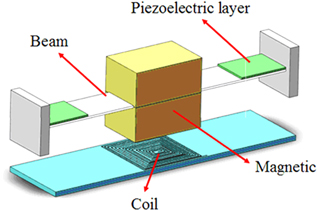
Figure 1. A common hybrid PE and EM energy harvesting system.
Download figure:
Standard image High-resolution image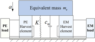
Figure 2. An equivalent model for a hybrid PE and EM energy harvester.
Download figure:
Standard image High-resolution image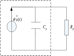
Figure 3. Equivalent circuit of a PE harvesting element.
Download figure:
Standard image High-resolution image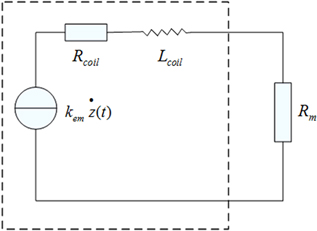
Figure 4. Equivalent circuit of an EM harvesting element.
Download figure:
Standard image High-resolution imageLet  be the displacement of the magnet, Vp
be the output voltage of the PE harvesting element and Iem
be the output current of the EM harvesting element. The governing equations of the piezoelectric-only energy harvester can be described by [33]
be the displacement of the magnet, Vp
be the output voltage of the PE harvesting element and Iem
be the output current of the EM harvesting element. The governing equations of the piezoelectric-only energy harvester can be described by [33]


where  is the applied acceleration.
Therefore, using an analogy method, the governing electromechanical equation of the hybrid piezoelectric and electromagnetic energy harvester can be expressed as


Equations (4) and (5) are derived from figures 4 and 3 by KCL (Kirchhoff's current law) and KVL (Kirchhoff's voltage law), respectively [34].
According to references, [26, 31, 35] the inductance of the coil can be neglected in the low vibrating frequency (lower than 1 kHz) because the impedance is mainly determined by the resistance of coil. Hence, equations (4) and (5) can be expressed in the frequency domain:

So the transfer function of the harvesting system giving the displacement as a function of the applied acceleration is given by:
where  is the correct factor for the SDOF model of the harvester [32]. Suppose the source of the forcing function comes from the vibration of the base of the structure, and this gives
  . Then the amplitude of magnet at any frequency
  is
is
where  is the magnitude of the acceleration. As illustrated in equation (8), the vibration characteristics of the hybrid energy harvester are affected by the coupling effect of the PE harvest element and the EM harvest element. In particular, the coupling effect of the PE element changes the effective stiffness and damping coefficient of the harvesting system, while that of the EM element just influences the effective damping coefficient. Thus, the effective stiffness and damping coefficient of the hybrid energy harvester at any excitation frequency
  are shown, respectively, as


Similarly, equation (6) is rearranged as

Thus, the output power of the PE and EM harvesting elements can be calculated, respectively, by

In equation (11), it can be concluded that the power of the PE element for the hybrid energy harvester is not only decided by the piezoelectric properties' parameters, but is also affected by the electromagnetic properties' parameters because of the coupling effect. Conversely, the power of the EM element is also influenced by the PE properties' parameters.
Lastly, the total power of the harvesting system is
Suppose that
 as the piezoelectric coupling coefficient;
 as the electromagnetic coupling coefficient;
 as the normalized frequency;
 as the mechanical damping ratio;
 as the normalized load resistance of the PE harvesting element.
 as the normalized load resistance of the EM harvesting element.
The normalized vibration magnitude and output power of the hybrid energy harvester are then described by
As shown in equations (13) and (14), the normalized displacement and power mainly depend on the vibration frequency  , the mechanical damping ratio
  , the electromechanical coupling coefficients
  and
and  , and the normalized loads
  and
and  . Thus, the scheme to optimize the power is either by adjusting the coupling coefficient and damping ratio by optimal structure design or selecting the optimal load and exciting at a suitable vibration frequency.
When  , the normalized displacement and power of the piezoelectric-only energy harvester are

When  , the normalized displacement and power of electromagnetic-only energy harvester are
where  is the correct factor of electromagnetic coupling coefficient when the electromagnetic-only energy harvester is working.
Compared with the output characteristics of the two separated devices in equations (15)–(18), the performance of the hybrid energy harvester is affected by the coupling among the PE element, the EM element and the mechanical element simultaneously.
2.2. Resonant frequency
According to equations (9) and (10), the effective stiffness and damping coefficient of the hybrid energy harvester cannot remain constant like a conventional second-order vibration system because they are related to the excited frequency, the load resistor and the coupling coefficient. Therefore, the resonant frequency of the hybrid energy harvester is no longer equal to the natural frequency that is designed aiming at environment frequency.
From references [31, 32], the vibration energy harvesters output the maximum power at the resonant frequency. In order to move the resonant frequency into the expected frequency range, the shift values of the resonant frequency relative to the natural frequency need to be studied for different coupling effects and loads for the hybrid energy harvester.
When the harvester is excited at resonance, the value of displacement is also maximal. Therefore, the resonant frequency can be calculated by the derivative of the expression of displacement. Then, suppose  . Because
  and
and
the solution of  can be derived, such that
and simplified to

which is a Cartan equation, and  ,
,  are given by


Equation (21) can be solved according to the value of the Cartan discriminant

and the solution is
where  .
.
Combining equations (22), (23) and (25), it can be concluded that the resonant frequency of the hybrid energy harvester is affected by structural characteristics (the damping ratio  and coupling coefficients
  ) and the normalized loads
  . Therefore, the resonant frequency of the hybrid energy harvester shifts when the coupling coefficient and the load resistor vary, and we will discuss the effect of these factors on the resonant frequency in section 4. In addition, substituting equation (25) into equations (13) and (14), the normalized displacement and power can be calculated at resonance.
3. Conversion efficiency
The efficiency of the mechanical-to-electrical energy conversion is a fundamental parameter for the development and optimization of a power generation device [36]. When the harvester is excited by a harmonic forcing function, Lefeuvre et al [37] and Tang et al [20] assumed that the phase between  and
and  is 90° at resonance, so the excitation force F and displacement z can be expressed

Then the efficiency of the power output is defined as the time-averaged energy ratio, that is

where  is the power dissipated across the load, and
  is the input power by the excitation force.
In one period vibration, the energy that is input into the harvester is

Substitute equation (26) into equation (28), and the result is

so

Then the efficiency can be expressed in equation (31) by substituting equation (12) into equation (27).
Similarly, the efficiency can be normalized by the non-dimensional parameters defined in section 2.1, and the result is
As demonstrated in equation (32), the efficiency of the power output is also decided by the coupling coefficient, the normalized load resistance and the normalized frequency. Supposing  ,
,  ,
,  ,
,  and
and  are fixed, then the optimal efficiency of the power output for the hybrid energy harvester is obtained by tuning the excitation frequency
  . The selection of the load resistance is also important to maximize the efficiency, and we will discuss this in section four.
When  , the conversion efficiency of the piezoelectric-only energy harvester is
When  , the conversion efficiency of the electromagnetic-only energy harvester is
By the analysis results in sections 2 and 3, we can see that the vibration and output characteristics of the hybrid energy harvester all depend on the damping ratio, excitation frequency, load resistor and coupling coefficient. Therefore, for designing a harvester, the performance is different when these parameters vary, which we will discuss in the next section.
4. Discussion
For a vibration energy harvester, the selection of the operating frequency is very important for achieving the maximum power, so the shift of resonant frequency for the hybrid piezoelectric and electromagnetic energy harvester is investigated at different coupling strengths and load resistance in this section. For the equivalent second-order system model, the power attains its maximum value at the load match. Although equation (14) extensively describes the characteristics of the hybrid harvesting system, its complicated nature makes it difficult to derive the closed form solution of optimal load resistance because of the electromechanical coupling effect. Thus, we try to obtain the optimal load through analyzing the maximal power of the hybrid energy harvester when the load resistance of the PE and EM harvesting elements are changed. In addition, while the harvesting system is excited at resonant frequency and connected with an optimal load resistor, it is proposed to analyze the performances of the hybrid piezoelectric and electromagnetic energy harvester in the various coupling strengths by comparing it with harvesters using only one conversion technique.
In the literature [6, 20, 21], the ratio between the piezoelectric coupling coefficient and the damping ratio has been proposed as an indictor of the strength of the coupling effect for the piezoelectric energy harvester. By analogy, here  (where
  is the total coupling coefficient for the hybrid energy harvester, and
  ) is used as an index to measure the magnitude of the coupling effect for the hybrid energy harvester. Therefore, we discuss the functional behavior of the hybrid energy harvester according to the different ranges of
  In this case, the expressions of normalized displacement, power and conversion efficiency are converted into
Then, we calculate the ratio between the coupling coefficient and the damping ratio of the designed energy harvesters described in the references, as illustrated in table 1.
Table 1. Physical characteristics of energy harvesters.
| References | Harvesting mechanism | Damping Ratio 
|
Coupling coefficient 
|

|
|---|---|---|---|---|
| Vinod et al (meso) [22] | EM | 0.036 | 0.038 | 1.1 |
| Spreemann (micro) [31] | EM | 0.03 | 0.01 | 0.33 |
| Vinod et al (meso) [26] | EM | 0.027 | 0.022 | 1.78 |
| PE | 0.026 | |||
| C Serre (micro) [35] | EM | 0.011 | 0.0013 | 0.12 |
| Yang (micro) [30] | EM | N/A (tested in air) | 0.0016 | 0.5 (suppose ζm = 0.02) |
| PE | 0.009 | |||
| Wacharasindhu (micro) [25] | EM | N/A (tested in air) | 0.0042 | 0.63 (suppose ζm = 0.02) |
| PE | 0.0085 | |||
| Robert (micro) [27] | PE | 0.02 | 0.0025 | 0.12 |
| Kasyap (micro) [38] | PE | 0.01 | 0.0012 | 0.13 |
| Tang (meso) [20, 39] | PE | 0.011 | 0.018 | 1.64 |
It is clear from table 1 that the ranges of  for these harvesters are from 0.12 to 1.78, which also reveals that the
  of the meso-harvesters is around 2, while the
  of the micro-harvesters is much smaller than 2. On the basis of the above numerical results and equations (35)–(37), we define three kinds of coupling strength by comparing
  with the value 2: weak coupling, medium coupling and strong coupling.
4.1. Weak coupling
Suppose that  for weak coupling. In this case, the vibration characteristics are almost independent of the feedback effect of the electric element, and the mechanical energy is mainly dissipated by damping.
In table 1, most of the micro-harvesters belong to the weak coupling group. Thus, the performance of the hybrid energy harvester in weak coupling is investigated to give methods of optimizing power for the micro-hybrid energy harvesters. Assume the mechanical damping ratio  and coupling coefficient
  in the following study, so
  corresponds to a weak coupling. In order to analyze the effect of each coupling coefficient of the hybrid energy harvester on the performance, two different cases are considered:
  and
and  . When
  , suppose that
  and
and  . Conversely, when
  , suppose that
  and
and  . For these two cases, figure 5 demonstrates the normalized resonant frequency at an arbitrary load resistance for the hybrid energy harvester.
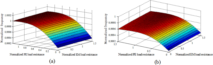
Figure 5. Resonant frequency of harvesting systems with different load resistance at weak coupling: (a) ηm < ηp; (b) ηm > ηp.
Download figure:
Standard image High-resolution imageFrom the analysis results in figure 5, although the shift of the resonant frequency for weak coupling is relatively small, a definite relation exists between the resonant frequency and the load resistance of the PE and EM harvesting elements, which is that the resonant frequency increases with an increased load resistance, and which keeps constant after reaching the maximum value. At the same time, no matter whether  or
or  , the normalized resonant frequency mainly depends on the normalized PE load resistance instead of the EM load. Thus, for weak coupling, the resonant frequency is almost equal to the natural frequency of the hybrid energy harvester.
The normalized displacement, power and conversion efficiency are plotted against the normalized load resistance of the hybrid energy harvester in figure 6, based on the analytical solution at resonance, and it can be concluded that the normalized displacement increases as the EM load resistance increases until it attains a maximum, and it exibits a minimum value at  . On the other hand, the normalized power and conversion efficiency reach a peak value when
  and
and  simultaneously, which means the optimal PE load resistance is 1/ωCp and the optimal EM load resistance is
  for the weak coupling effect. Therefore, the internal resistance of the hybrid energy harvester is not affected by the coupling effect at the weak coupling.

Figure 6. Harvester performance in the case of weak coupling with different load resistance: (a)–(c) are the normalized displacement, power and conversion efficiency when ηm < ηp; (d)–(f) are the normalized displacement, power and conversion efficiency when ηm > ηp.
Download figure:
Standard image High-resolution imageIn the optimal load resistance, the normalized displacement, power and conversion efficiency against the excitation frequency are numerically calculated and compared with only the PE or EM energy harvester, as illustrated in figure 7. It is clear from analysis results that the power and conversion efficiencies of the hybrid energy harvester are bigger than those of the PE-only or EM-only energy harvesters, although the values of displacement are almost equal. Moreover, the hybrid energy harvesting techniques can enhance the bandwidth at the same condition, which is a conclusion also reached by Lallart and Inman [29]. However, the energy conversion efficiency is less than 10% at the weak coupling effect, so most of the mechanical energy is lost because of the mechanical damping ratio and internal resistance.
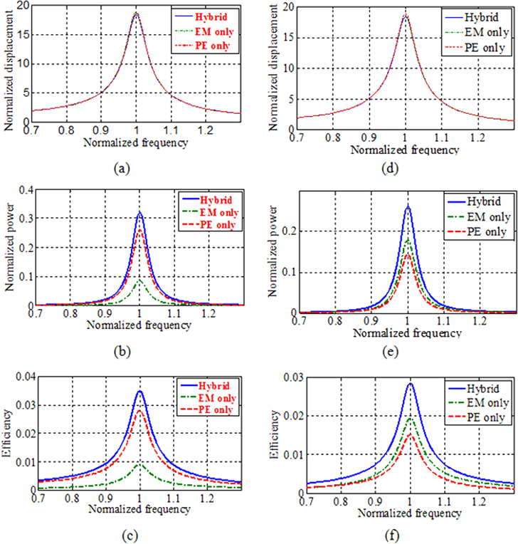
Figure 7. Comparison in the case of weak coupling at different excitation frequencies: (a)–(c) are the normalized displacement, power and conversion efficiency when ηm < ηp; (d)–(f) are the normalized displacement, power and conversion efficiency when ηm > ηp.
Download figure:
Standard image High-resolution imageIn addition, the power and conversion efficiency of the hybrid energy harvester at η m < η p is bigger than the situation of ηm > ηp when the total coefficient stays at one value. Thus, for the hybrid energy harvester, although the total coupling coefficient is the same, the power is decided by each value of the PE and EM coupling coefficient. Moreover, for weak coupling, the hybrid energy harvesting technique should be adopted instead of single the harvesting mechanism.
4.2. Medium coupling
We define the medium coupling as (ηm + ηp )/ζm ≈ 2, and table 1 reveals that most of the meso-harvesters belong to this case. At this time, the feedback effect of the electric-element and mechanical damping has the equivalent effect on the harvesting system.
Suppose ηm + ηp = 0.05 and ζm = 0.026, then (ηm + ηp )/ζm = 1.923, which are typical parameters for PE and EM power generators designed as the meso-structure [36]. According to the analysis results in table 1, the effects of the coupling coefficient on the performance for the hybrid energy harvester are classified into three cases: (1) EM medium coupling and PE weak coupling; (2) PE medium coupling and EM weak coupling; and (3) EM medium coupling and PE medium coupling. Here we assume that ηm = 0.045 and ηp = 0.005 for case 1; ηm = 0.005 and ηp = 0.045 for case 2; and ηm = 0.025 and ηp = 0.025 for case 3. Then, the resonant frequency is numerically calculated for medium coupling when the load resistance of the PE and EM elements vary, and results are shown in figures 8(a), (e) and 9(a), which reveal that although the shift of the resonant frequency for medium coupling is much bigger than that for weak coupling, the change law is similar. Therefore, the conclusion can be reached that the shift of the resonant frequency is proportional to the coupling coefficient for the hybrid energy harvester. However, in contrast with two others of medium coupling, the extent of the resonant frequency shift is more obvious when the harvester is in the state of EM weak coupling and PE medium coupling.
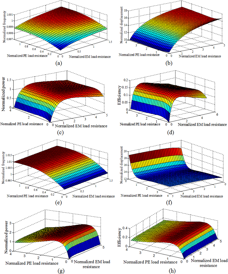
Figure 8. Effect of load resistance on the performance of the hybrid energy harvester (medium coupling): (a)–(d) are the resonant frequency, normalized displacement, power and conversion efficiency for EM medium coupling and PE weak coupling; (e)–(h) are the resonant frequency, normalized displacement, power and conversion efficiency for EM weak coupling and PE medium coupling.
Download figure:
Standard image High-resolution image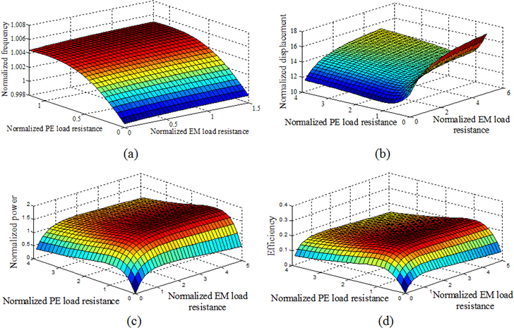
Figure 9. Effect of load resistance on performance of the hybrid energy harvester at EM medium coupling and PE medium coupling: (a)–(d) are the resonant frequency, normalized displacement, power and conversion efficiency, respectively.
Download figure:
Standard image High-resolution imageWhen the hybrid energy harvester is excited at the resonant frequency, the normalized displacement, power and conversion efficiency versus load resistance are as shown in figures 8(b)–(d), (f)–(h) and 9(b)–(d), so the performance of the harvester is mainly decided by the PE coupling coefficient for EM weak coupling and PE medium coupling. Conversely, they are mainly related to the EM coupling coefficient for EM medium coupling and PE weak coupling. Therefore, it can be said that the coupling coefficient directly affects the vibration characteristics and performance of the hybrid energy harvester. The load resistance is optimal while the power reaches a maximum value. When ηm = 0.045 and ηp = 0.005, the optimal load resistances are rm = 2.1 and rp = 1 simultaneously for the hybrid energy harvesting; while the optimal normalized load is rp = 1 and rm = 4.1 at ηm = 0.005 and ηp = 0.045, as illustrated in figures 8(c), (g) and 9(c). At the same time, when ηm = 0.025 and ηp = 0.025, the optimal load resistances are rm = 2.9 and rp = 1 for the hybrid energy harvesting while the optimal loads are rm = 1.6 and rp = 1 for the EM-only and PE-only energy harvesters, respectively. Therefore, it can be concluded that the internal resistance of the EM harvest element increases as the coupling effect of the hybrid energy harvester is enhanced. However, the optimal PE load resistance is almost unchanged at the medium coupling effect. In addition, the optimal EM load is influenced by the PE coupling efficient, and the greater the PE coupling coefficient, the bigger the optimal load resistance of the EM element. Furthermore, the optimal power of the hybrid energy harvester allows the sensitivity to EM load resistance to decrease.
When the hybrid energy harvester is connected with an optimal load, the normalized displacement, power and conversion efficiency against the normalized frequency are plotted in figures 10 and 11, which demonstrate that the shift of resonant frequency mainly relates to the PE coupling coefficient instead of the EM coupling efficient. Compared with the weak coupling, the conversion efficiency of the hybrid energy harvester is much bigger for medium coupling, which means that much more energy is converted into electric energy instead of being lost by damping. Moreover, the conversion efficiency of the harvester at EM weak coupling and PE medium coupling is bigger than any other two cases of medium coupling; in particular, the efficiency is up to 30%.
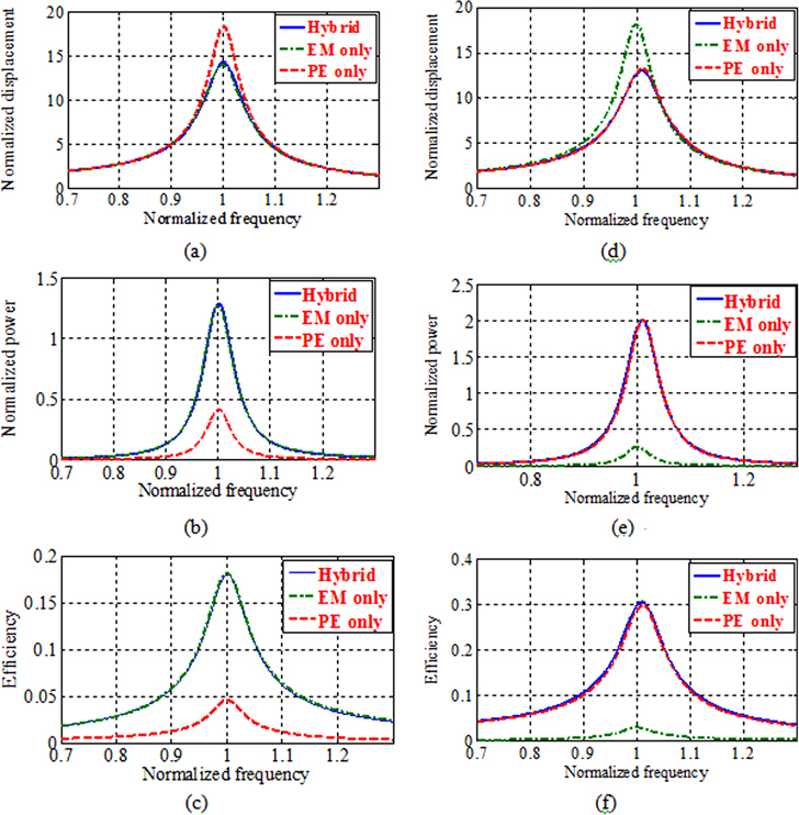
Figure 10. Effect of frequency on performance of the hybrid energy harvester (medium coupling): (a)–(c) are the normalized displacement, power and conversion efficiency for EM medium coupling and PE weak coupling; (d)–(f) are the normalized displacement, power and conversion efficiency for EM weak coupling and PE medium coupling.
Download figure:
Standard image High-resolution image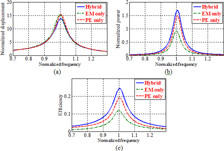
Figure 11. Effect of frequency on performance of the hybrid energy harvester (EM medium coupling and PE medium coupling): (a)–(c) are the normalized displacement, power and conversion efficiency, respectively.
Download figure:
Standard image High-resolution imageIn addition, the power of the hybrid energy harvester is not increased compared with the PE-only energy harvester at EM weak coupling and PE medium coupling, or of the EM-only energy harvester at EM medium coupling and PE weak coupling. The former situation should take into account the internal loss of the electromagnetic transducer element, and the latter may be caused by the stiffness variation after combing the PE harvesting element. Furthermore, compared with only one conversion technique, the power of the hybrid energy harvester is much bigger, and the bandwidth is much wider for EM medium coupling and PE medium coupling, which is the same result as the experimental test in [26, 29].
Therefore, as the electromechanical coupling coefficient increases, the total power will not definitely increase after combining the PE and EM energy harvester, but depends on the cases of each value of the PE and EM coupling coefficients, which need to be considered in designing the hybrid energy harvester. At the same time, according to analysis results, the output of the hybrid energy harvester is mainly decided by the PE element for PE medium coupling and EM weak coupling; similarly, the harvester output is mainly related to the EM element for EM medium coupling and PE weak coupling. Therefore, compared with the case of EM medium coupling and PE medium coupling, the current of the hybrid energy harvest is still relatively small for EM weak coupling and PE medium coupling, and the voltage is also not increased for EM medium coupling and PE weak coupling. For these two cases, the performance of the hybrid energy harvester cannot achieve both a big current and voltage output. Hence, the hybrid energy harvester designed with EM medium coupling and PE medium coupling could enhance the output power and conversion efficiency.
4.3. Strong coupling
Define the strong coupling as (ηm + ηp )/ζm ≫⃒ 2, which is a special case for the energy harvester, but may be achieved by an SSHI (synchronized switch harvesting on inductor) technique for boosting the power [20, 21]. Suppose that ηm = ηp = 0.1 and ζm = 0.026, then (ηm + ηp )/ζm = 7.69. In this case, the feedback effect of the electric element on the harvesting system is much greater than the mechanical damping, so the coupling coefficient plays a major role in energy transfer, and the most of mechanical energy will be converted into electric energy by the harvester.
Using equation (25), the resonant frequency of the hybrid energy harvester is numerically calculated with a different load resistance for strong coupling. The results, given by figure 12(a), indicate that the resonant frequency shift of strong coupling is much greater than that of weak coupling and medium coupling. Similarly, the resonant frequency increases with the increase of the load resistance of the PE element and the EM element, and the normalized frequency is mainly related to the PE coupling coefficient compared to the EM coupling coefficient.
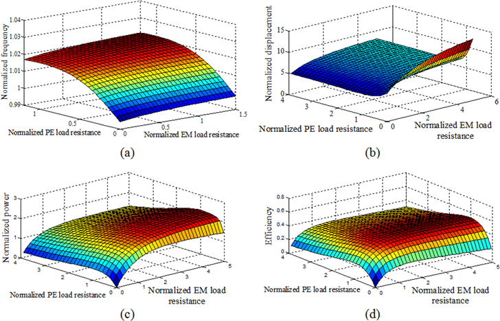
Figure 12. Effect of load resistance on performance of the hybrid energy harvester withstrong coupling: (a)–(d) are the resonant frequency, normalized displacement, power and conversion efficiency, respectively.
Download figure:
Standard image High-resolution imageWhen the harvesting system is excited at the resonant frequency, the corresponding normalized displacement, power and conversion efficiency for strong coupling are as shown in figures 12(b)–(d), which shows that the variation law of the normalized resonant frequency against the normalized load resistance is the same as the conclusions with weak coupling and medium coupling. However, when ηm = ηp = 0.1, the normalized load resistance corresponding to the maximum power is rm = 8 and rp = 1 for the hybrid energy harvester, while the optimal load resistance is 3Rcoil and 1/ωCp for the EM-only and PE-only energy harvester, respectively. Hence, it can be concluded that the internal resistance difference between the hybrid energy harvester and the EM-only harvester increases as the coupling coefficient is enhanced.
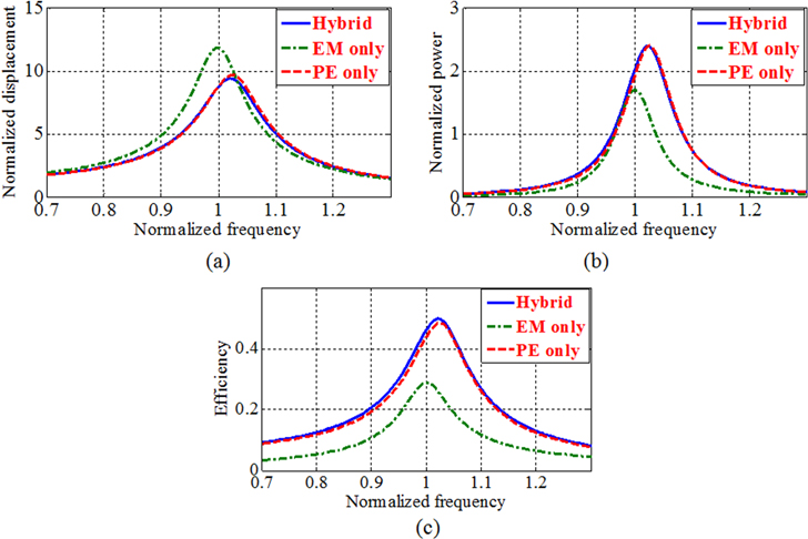
With the optimal load, the normalized displacement, power and conversion efficiency versus the normalized frequency are numerically calculated, and the results are plotted in figure 13, which reveals that the resonant frequency shift of the strong coupling is much greater than that of the weak coupling and medium coupling. In addition, the total power and conversion efficiency further increase when the coupling effect rises from weak coupling to strong coupling. Moreover, the efficiency can be up to 50% when the hybrid energy harvester is of the strong coupling type, which means that the bigger the coupling effect, the more the electric energy output.
Figure 13. Effect of frequency on performance of the hybrid energy harvester with strong coupling: (a)–(c) are the normalized displacement, power and conversion efficiency, respectively.
Download figure:
Standard image High-resolution image
From figure 13, the total power of the hybrid energy harvester is bigger than that of the EM-only harvester, but is almost equal to that of the PE-only harvester. Furthermore, the conversion efficiency has the same conclusion with the output power, and the harvesting bandwidth is just equal to the PE-only energy harvester. According to equation (36), the perfomance of the hybrid energy harvester in strong coupling is mainly determined by the coupling coefficient compared with the damping ratio, which means that the electric output feedback of the piezoelectric and electromagnetic elements for strong coupling are much bigger than those of weak and medium coupling. Therefore, the effective stiffness and damping are much bigger in strong coupling. In addition, the internal resistance of the hybrid harvester increases as the coupling coefficient strengthens. It can be determined that there is much more power loss for strong coupling because of the effective electric damping and internal resistance, and the power output of the electromagnetic element in the hybrid device may be consumed because of the strong coupling effect. Thus, it can be concluded that the total power and conversion efficiency of the hybrid energy harvester are no longer raised compared with the PE-only harvester when the coupling coefficient is up to strong coupling.
5. Conclusions
In this paper, we have presented an investigation of the electromechanical coupling effect of a hybrid energy harvester. An analytical model of hybrid energy harvesting is proposed, and the exact formulae of the resonant frequency shift, displacement, power and conversion efficiency are derived. It is shown that the performance of the hybrid energy harvester mainly depends on the coupling coefficient, mechanical damping ratio, excitation frequency and load resistor.
In addition, the performance of the hybrid energy harvester is investigated when the harvester is at weak coupling, medium coupling and strong coupling, when connected with different load resistances and excited at resonance or off-resonance frequencies. It is shown that a combined piezoelectric and electromagnetic harvesting mechanism can boost the power and conversion efficiency at weak coupling and medium coupling (just PE medium coupling and EM medium coupling) compared with two separate harvesters, while it cannot increase the power at strong coupling compared with piezoelectric-only energy harvesting. Moreover, the internal resistance of the EM harvesting element increases as the coupling effect is enhanced, and the internal resistance difference between the hybrid energy harvester and the EM-only harvester also increases as the coupling coefficient is strengthened. The bigger the coupling strength, the less energy loss there is by mechanical damping, and the more mechanical energy is converted into electric energy. Furthermore, although the total coupling coefficient of the hybrid energy harvester is the same, the performance varies when the coupling coefficient of two harvesting elements are different.
Therefore, the hybrid piezoelectric and electromagnetic energy harvesting technique should be used with weak coupling and PE and EM medium coupling.
Acknowledgments
This project is supported by the National High Technology Research and Development Program of China (grant No. 2013AA041104).