

Abstract
This paper describes a new three-dimensional (3D) fused filament additive manufacturing (AM) technique in which electroactive polymer filament material is used to build soft active 3D structures, layer by layer. Specifically, the unique actuation and sensing properties of ionic polymer-metal composites (IPMCs) are exploited in 3D printing to create electroactive polymer structures for application in soft robotics and bio-inspired systems. The process begins with extruding a precursor material (non-acid Nafion precursor resin) into a thermoplastic filament for 3D printing. The filament is then used by a custom-designed 3D printer to manufacture the desired soft polymer structures, layer by layer. Since at this stage the 3D-printed samples are not yet electroactive, a chemical functionalization process follows, consisting in hydrolyzing the precursor samples in an aqueous solution of potassium hydroxide and dimethyl sulfoxide. Upon functionalization, metal electrodes are applied on the samples through an electroless plating process, which enables the 3D-printed IPMC structures to be controlled by voltage signals for actuation (or to act as sensors). This innovative AM process is described in detail and the performance of 3D printed IPMC actuators is compared to an IPMC actuator fabricated from commercially available Nafion sheet material. The experimental results show comparable performance between the two types of actuators, demonstrating the potential and feasibility of creating functional 3D-printed IPMCs.
Export citation and abstract BibTeX RIS
1. Introduction
Fused filament additive manufacturing (AM), such as three-dimensional (3D) printing, is a manufacturing technique in which plastic and/or metal materials are deposited in layers to produce a 3D structure, with complex shapes and features [1]. Typically, non-electroactive plastics, such as acrylonitrile butadiene styrene (ABS) and polylactic acid (PLA), are used to create components in applications ranging from medical devices to robotics [2]. In contrast, presented here is a novel fused filament AM technique using electroactive ionomeric polymer material to create 3D soft ionic polymer-metal composite (IPMC) electroactive structures for applications such as soft robotics and novel biomedical and bio-inspired actuators and sensors. The proposed AM concept is illustrated in figure 1. First, a solid model of a soft active structure, for example the body of a soft robotic system, is created in a computer-aided design (CAD) software package as illustrated in figure 1(a). Ideally, the body would be a monolithic structure designed with certain sections having actuation capabilities and others with sensing capabilities. Next, the solid model is sent to a custom-designed 3D printer that utilizes an ionomeric precursor filament material to manufacture the soft 3D polymer structure, layer by layer, as shown in figure 1(b). The manufactured component is then chemically 'activated' and plated with electrodes as shown in figure 1(c), to create a fully electroactive body. This is done by hydrolyzing the printed precursor material in an aqueous solution of potassium hydroxide (KOH) and dimethyl sulfoxide (DMSO,  ), then applying an electroless plating process to create electrodes at the polymer surface. Finally, electronics and a power source can be added to the manufactured structure to create the complete robotic system with built-in actuation and sensing capabilities, as shown in figure 1(d). Thus, the unique actuation and sensing properties of IPMCs are exploited directly in 3D printing process to create electroactive polymer actuators and sensors with application in soft robotics and bio-inspired systems. The contribution of this paper is the detailed description of the proposed AM process for IPMCs and presenting experimental results that demonstrate the potential and feasibility of creating 3D-printed IPMC actuator samples.

Figure 1. Fused filament 3D printing to create IPMC-based soft active structure: (a) device designed using computer aided design (CAD) software. (b) Model is sent to a 3D printer that uses precursor filament material for 3D printing. (c) The body is 'activated' and electrodes are applied using an electroless plating procedure. (d) Finally, electronics and a power source are added to create a monolithic soft robotic system.
Download figure:
Standard image High-resolution imageIPMCs consist of an ion exchange membrane (such as the perfluorosulfonic polymer, Nafion), neutralized with mobile cations (such as lithium or sodium), and sandwiched between two noble metal (typically platinum) electrodes [3–5]. When the IPMC is hydrated with a solvent, such as water, application of an electric potential across the electrodes causes the cations to move toward the cathode, dragging along solvent molecules. Solvent accumulation at the cathode side causes differential 'swelling' in the ionomeric material and, therefore, macroscopic bending. As a result, the electromechanical response of the IPMC material allows it to function as an actuator. Conversely, if the IPMC is deformed, the cations redistribute and create a voltage signal across the electrodes [3, 5, 6]. Therefore, IPMCs can also be used as sensors. Some of the advantages of IPMCs include low actuation voltage  5 V), flexibility, softness, and that they are easy to shape. Given these characteristics, IPMCs are attractive for use in a wide variety of soft active systems, including active tube-like structures and catheters [7, 8], physical sensors [9], micro pumps [10–13], and propulsion mechanisms for underwater robotics [14–17].
Conventional means of fabricating IPMCs consist of shaping and plating commercially available Nafion sheets or tubular structures or other ion exchange membranes. Existing IPMC actuators and sensors are manufactured in limited shapes, primarily thin sheet-like or tube-shaped structures. To overcome this limitation, researchers have created other shapes either by fusing multiple commercially manufactured membranes together via a hot pressing method [18] to create thicker structures or by dispensing dispersions of Nafion into a cast [19] or extrusion [20]. But these methods still only produce limited, predefined shapes. Novel lithographic techniques have been exploited to fabricate planar IPMCs with integrated electrodes [21, 22]. Free-form layer-by-layer manufacturing of IPMCs is described in [23] and [24]. Therein, layers of Nafion dispersions are dispersed into silicone casts and the solvent in the dispersion is allowed to evaporate away. A micro deposition method employing ink-jet technology was also developed based on the use of Nafion dispersions in [25]. By contrast, the 3D printing method proposed here is a fused filament AM technique. It allows the manufacturing of monolithic millimeter scale or larger soft 3D IPMCs structures with sub-millimeter scale precision, at a fast rate, with an accessible 3D-printing technology.
Related soft active structures and robots have been manufactured via nano-imprint methods, laser imaging, laser ablation, micro injection molding, embedded molding and, recently, soft material deposition processes have also been explored [26, 27]. However, subsequent to these processes, separately manufactured actuators such as thermally activated joints [28], shape memory alloys [29], or piezoelectric fibers [30] have had to be embedded into the soft structure to create a composite active soft structure [27]. Thus, the manufacturing of such soft complex devices involves fabricating a soft passive structure (non-electroactive) and then attaching and/or embedding actuators (such as dc motors or pneumatics) and sensors (such as strain gages) for motion control and sensing [27]. Herein, the proposed 3D printing process directly incorporates the electroactive polymer material during manufacturing for rapid production of soft electroactive structures with integrated actuators and sensors. Additionally, the 3D printing technology can also incorporate other materials such as PLA and ABS to create composite active structures for robotics and biomedical applications. To demonstrate the potential and feasibility of creating functional 3D-printed IPMC structures, sample 3D printed IPMC actuators are created and their performance is compared to an IPMC actuator fabricated from commercially available Nafion sheet material. Experimental results are presented that show comparable performance between the two actuators.
2. 3D printing of IPMC
Nafion is the most commonly used material to create IPMCs [3, 5]. Nafion consists of a hydrophobic tetrafluoroethylene (Teflon) backbone and hydrophilic perfluorovinyl ether side chains, with sulfonate end groups [31]. When hydrated, a network of hydrophilic regions is formed and the sulfonate end groups of the side chains disassociate from their cations. Those cations then constitute free charges which are able to migrate through the hydrophilic network, giving Nafion its characteristic conductivity [31]. Unfortunately, the ionic end groups that are responsible for this characteristic functionality of 'active' Nafion, also prevents it from being melt processable [32]. Therefore, in order to extrude, print or otherwise melt-process Nafion, it is necessary to obtain Nafion in its sulfonyl fluoride precursor form which, in contrast, is melt processable. Thus, after the precursor polymer is formed into its desired geometry, it has to be 'activated' via a hydrolysis process that converts the sulfonyl end groups to sulfonic acid or salt. The 'active' Nafion can then be plated using any effective plating procedure to create functional IPMCs [5, 33–35]. The details of the 3D printing technique for IPMCs are presented in this section. First, the extrusion of the precursor filament for use in the custom-designed 3D printer is discussed. Then, the design of the 3D printer and the 3D printing process tuning are presented. Finally, the activation and electrode plating process are described.
2.1. Filament extrusion
Nafion precursor filament is created for the 3D printer using a custom-designed extruder. The extruder and its main components are shown in figure 2. The extruder consists of a hopper loaded with commercially available pellets of the Nafion precursor polymer (NAFION® R1100 Precursor Beads, Ion Power, Inc., New Castle, DE), and a single screw drive auger (5/8 inch diameter, 0.66 threads per inch, single fluted) coupled to a 24 V dc motor (with a 1:144 gear ratio) which feeds the raw polymer through a conduit to a heated nozzle. The nozzle tapers down to the nominal desired filament diameter of 1.75 mm. The 3D printer nozzle and filament feed mechanism were designed to accommodate this filament diameter. Down stream of the extruder, the filament is drawn by a pair of rollers driven by another dc motor.
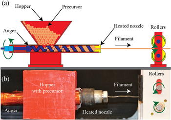
Figure 2. Nafion precursor filament extruder: (a) diagram of main components such as an auger, a hopper, a heated nozzle, and rollers. (b) Photograph of custom-designed extruder.
Download figure:
Standard image High-resolution imageThe extrusion of the Nafion filament was conducted between 280 °C and 300 °C. Extrusion speed varies between 25–125 mm s−1 depending on temperature, motor voltage (between 10 and 24 V), and the amount of material in the auger. It was found that it was effective to draw the material at a slightly lower speed than it was being extruded, to prevent significant necking. The extrusion was conducted in a fume hood due to the potential for the production of hydrogen fluoride (HF) and other toxic gases when Nafion precursor is heated.
Examples of the Nafion filament obtained are shown in figure 3. The discoloration in the filament on the right is attributed to contamination possibly caused by accelerated oxidation of the extruder components. This would be the result of the release of trace amounts of HF during the extrusion process. This discoloration dissipated during the printing process and subsequent chemical treatments. The filament obtained was soft and flexible and had a Teflon-like texture. The resulting diameter of the extruded Nafion filament was 1.75 ± 0.1 mm.
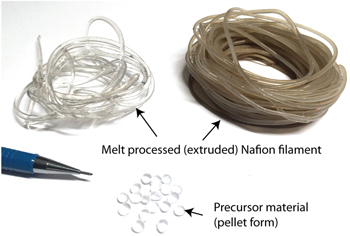
Figure 3. Samples of Nafion precursor filament obtained from extruding it as described. Discoloration in the filament to the right is from some slight contamination.
Download figure:
Standard image High-resolution image2.2. 3D printer design
A custom designed 3D printer was created based on the commercially available Mendel RepRap 3D printer. As shown in figure 4(a), the printer consists of a two degree-of-freedom printing head, and a one degree-of-freedom heated build stage. The printing head system is custom designed to accommodate the high melting temperature of the Nafion precursor and the flexible nature of the precursor filament. This system, shown in figures 4(b) and (c), is comprised of a heated nozzle, a filament drive mechanism, and a thermal barrier. The heated nozzle uses a high-power flame-proof resistor to reach temperatures in excess of 300 °C. A thermistor is attached to the heated nozzle to relay the temperature measurement back to the printer electronics and computer for displaying the temperature. An external thermocouple temperature sensor was also attached to the heated nozzle to monitor and verify the temperature.
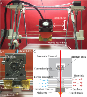
Figure 4. Custom-designed fused filament three-dimensional (3D) printer: (a) complete assembly of the custom 3D printer, (b) close-up view of the printer head and major components, and (c) illustration of the printer head showing additional details.
Download figure:
Standard image High-resolution imageThe filament drive mechanism is responsible for pushing the filament through the heated nozzle onto the build platform. The flexible nature of the precursor material requires the path of the filament to be highly constrained to prevent buckling of the filament. In addition, the transition region between the solid and melted precursor material is designed to be very small. This keeps the frictional forces of the filament against the inside of the barrel to a minimum and is accomplished by a custom designed thermal barrier between the filament drive and the heated nozzle .

Figure 5. Printed IPMC samples: (a) printed membranes of Nafion precursor and (b) IPMC actuators made from the printed membranes from (a), where platinum electrodes were applied via the electroless plating process. Dimension of each sample is approximately 30.5 mm by 11.5 mm by 1.0 mm.
Download figure:
Standard image High-resolution imageThe heated build stage can sustain temperatures above 200 °C. The Nafion precursor material is 'printed' onto the build stage by controlling the motion of the printing head and the build stage as the precursor material is extruded. Pronterface software is used to control the printer. The software uses gcode generated from Slic3r software, which slices stl-CAD models produced in SolidWorks CAD program. The effective settings for printing Nafion precursor material were found to be a bed temperature of approximately 180 °C, a nozzle temperature of 280 °C, and extrusion and travel rates comparable to that used for slow extrusion of ABS, typically around 30 mm s−1.
2.3. 3D printed IPMC samples
The 3D printer was used to create several Nafion precursor membranes as shown in figure 5(a). The printed membranes were then functionalized and platinum electrodes were applied using an electroless plating process to create IPMC actuators. These samples are shown in figure 5(b). One of the main reasons for creating rectangular-shaped 3D printed plate-like samples was to be able to study such structures and also provide meaningful comparison of the properties and performance of this new structure against traditional membrane-based IPMCs, which are fabricated from standard Nafion sheets. A comparison of one of the 3D printed membranes and fabricated IPMC actuator to conventional commercially obtained Nafion membrane and the IPMC fabricated from it are also shown in figure 6. In particular, figure 6(a1) is the 3D-printed Nafion precursor membrane and figure 6(a2) is the conventional commercially-available Nafion membrane. Optical images of the cross section of each membrane are shown in figures 6(b1) and (b2), where it is readily apparent that the surface morphology of the 3D printed membranes consists of undulated or 'ribbed' features caused by the in-fill pattern during printing whereas the conventional IPMC is flat and smooth. It is pointed out that the conventional IPMC was fabricated at the same time as the printed IPMCs, to act as a control for subsequent experiments. Each of the printed IPMCs are approximately 30.5 mm long and 11.5 mm wide with a thickness of 1.0 mm. The conventional IPMC is approximately 28.5 mm long and 13.0 mm wide with a thickness of 0.6 mm. The profile of the printed IPMC is shown in figures 6(c1) and (d1) and the profile and cross-section of the conventional IPMC is shown in figures 6(c2) and (d2). The line-trace profiles were taken from the optical images, figures 6(c1) and (c2), as indicated by the solid red line.
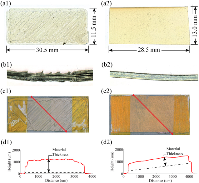
Figure 6. Printed and conventional samples: (a1) printed membranes of Nafion precursor. (b1) Cross-section of a printed IPMC (c1) An IPMC made from the printed membranes via the electroless plating process. (d1) Profile of printed IPMC. (a2) Membranes of Nafion cut from commercially obtained 0.5 mm thick stock. (b2) Cross-section of a conventional IPMC. (c2) An IPMC made from the commercially obtained Nafion membranes via the electroless plating process. (d2) Profile of conventional IPMC.
Download figure:
Standard image High-resolution imageThe 3D-printed membranes were functionalized by hydrolyzing them in a solution of 15 wt% KOH/35 wt% DMSO/50 wt% deionized water at 75 °C as prescribed by the manufacturer [36] (see figure 7(a)). The samples were then cleaned by soaking them in three successive baths of deionized water at 75 °C for 30 min each. Figure 7(b) shows how fluorine atoms on the sulfonyl end groups are exchanged with hydroxide from the solution and how the hydrogen ion from this hydroxide group is then exchanged with the potassium ion resulting in the potassium salt form, in the hydrolysis process [37]. This process proceeds from the surface of the polymer inward, as the hydrolysis of exterior layers allows the swelling of the membrane. Assuming a hydrolysis rate of approximately 1.3 μm per minute, a 0.5 mm thick sample would soak for 4 h to complete the hydrolysis and then for another 4 h to allow for the formation of ionic clusters throughout the material [37]. Complete hydrolysis of the samples was confirmed after approximately 4 h by the complete staining of a cross-section of the sample using methylene blue, which only dyes the 'activated' material [37] as shown in figures 7(e) and (f).

Figure 7. Activation of Nafion precursor material: (a) end groups of the precursor side chains in their sulfonyl fluoride form. (b) Fluorine atoms on the sulfonyl end groups are electrophilicly exchanged with hydroxyl ions. (c) The hydrogen ions in the hydroxyl group is nucleophilicly exchanged with the potassium ions. (d) A hydration sphere forms around the potassium ion, swelling the hydrolyzed material [37]. (e) A cross-section of Nafion precursor material soaked in methylene blue remains unstained. (f) A cross-section of fully hydrolyzed material soaked in methylene blue is completely stained.
Download figure:
Standard image High-resolution imageAs illustrated in figure 1(c), the 3D-printed membrane samples were then made into IPMCs by using the electroless plating process. The electroless plating process used here is similar to that reported in [33, 35], and the approach is divided into four distinct subprocesses: (1) the surface preparation, cleaning, and initial ion exchange process, (2) the primary plating process, (3) the secondary plating process, and (4) a final ion exchange process. Some processes are repeated multiple times. For instance, the secondary plating process is repeated until the resistance across the electrode surfaces is less than 5 Ω cm−1. There are cleaning steps at the end of the two plating processes to prevent contamination of subsequent processes. All processes are conducted in a fume hood due to the toxicity of the chemicals involved. The details of each process are described below:
- (1)Surface preparation, cleaning, and initial ion exchange process: With conventional Nafion membranes, the first step is to roughen the membrane with 200 grit sandpaper (where roughening is done in the direction of the intended bending axis), to increase the surface area of the interface between the Nafion and the electrode material [38]. This was not done to the printed samples to avoid damaging them and because it was presumed that the printed surface would not be as smooth as a conventional ion-exchange membrane. Next, the samples are hydrated by soaking them in DI water at 65 °C for 15 min. Then, the samples are soaked in 3 wt% H2O2 at 65 °C for 45 min. Next, the samples are soaked in DI water at 65 °C for 15 min. Afterwards, the samples are soaked in 15 wt%. H2SO4 at 65 °C for 45 min to clean the membrane and convert it to its acid form. In this step, the potassium ion from hydrolysis is replaced by a hydrogen ion. This is done to facilitate subsequent ion exchanges. The samples are then soaked in two more successive baths of (DI) water at 65 °C for 45 min.
- (2)Primary plating process: The samples are soaked in a 0.02 molar solution of tetraammineplatinum(II) chloride hydrate (Pt(NH3)4Cl2) for 3–4 h at room temperature. This accomplishes an ion exchange in the surface layers of the membrane in which the Pt+ ion replaces the
 ion. The membranes are then immersed in deionized water at 50 °C, to which a reducing agent (NaBH4) is added every 30 min for 3 h while slowly raising the temperature to 65 °C. This visibly metalizes the surface layers of the membrane. Afterwards, the samples are soaked in 0.5 M H2SO4 at 65 °C for 45 min, followed by soaking the samples in two successive baths of DI water at 65 °C for 45 min to clean them. This process is repeated once.
 - (3)Secondary plating process: The samples are again immersed in tetraammineplatinum(II) chloride hydrate (Pt(NH3)4Cl2) at 50 °C. However, reducing agents (5 wt% hydroxylamine hydrochloride and 20 wt% hydrazine) are this time added directly to the platinum salt solution, every 30 min, while slowly raising the temperature to 65 °C over the course of 3 h. This causes platinum to be deposited on the surface of the existing metalized layers, improving the electrical conductivity of these layers as well as the overall electrochemical properties of the IPMC [39]. Then the resistance of the electrodes is measured (using the two-point measurement technique) and if the resistance is above 5 Ω the process is repeated. Afterwards, the samples are soaked in 0.5 M H2SO4 at 65 °C for 45 min, followed by soaking the samples in two successive baths of DI water at 65 °C for 45 min to clean them.
- (4)Ion exchange process: The ion exchange process is done by soaking the membranes in a 1 molar LiCl solution at room temperature for 24 h. This converts the IPMCs into their lithium salt form, improving their actuation characteristics [34].

Scanning electron microscope (SEM) micrographs of a printed IPMC sample compared to the conventional IPMC sample are shown in figure 8. Images of the electrode surfaces of printed and conventional IPMCs are also compared in figure 9. Figure 8(a1) is a micrograph of a printed IPMC cross-section cut perpendicular to the print direction of the infill of the 3D printed sample, prior to plating. This illustrates the printed IPMCs' 'ribbed' surface as compared to the flat surface of the conventional IPMC in figure 8(a2). Figures 8(b1) and (b2) are of edges of a printed and conventional IPMC, respectively. These edges were trimmed after being plated exposing the Nafion layer of the IPMC. Figures 8(b1) and (b2) illustrate the similarity in the composition of the printed and conventional IPMCs.
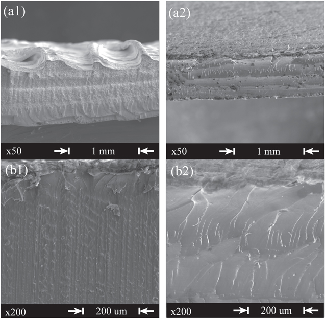
Figure 8. Scanning electron microscope (SEM) micrographs of a printed and conventional IPMC: (a1) cross-section of a printed IPMC cut perpendicular to printer in-fill at x50 mag. (a2) Edge of a conventional IPMC trimmed after plating at x50 mag. (b1) Edge of a printed IPMC trimmed after plating IPMC at x200 mag. (b2) Edge of a conventional IPMC trimmed after plating IPMC at x200 mag.
Download figure:
Standard image High-resolution image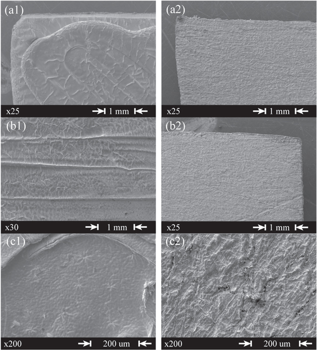
Figure 9. Scanning electron microscope (SEM) micrographs of the electrode surfaces of printed and conventional IPMCs: (a1) printed IPMC electrode surface at x25 mag. (a2) Conventional IPMC electrode surface at x25 mag. (b1) Printed IPMC electrode surface at x30 mag showing 'ribbed' surface from the printed infill. (b2) Conventional IPMC electrode surface at x25 mag. (c1) Printed IPMC electrode surface at x200 mag. (b2) Conventional IPMC electrode surface at x200 mag.
Download figure:
Standard image High-resolution imageLikewise, the electrode surface of the printed and conventional IPMCs are displayed in figure 9. The printed IPMC has a smoother surface than the conventional IPMC, which is possibly due to the roughening of the conventional Nafion membrane prior to plating. However both the printed and conventional IPMC exhibit a 'mud-cracked' texture caused by drying of the IPMCs and the consequent shrinking of the ionomer material [40]. One notable difference between the two is the 'ribbed' surface from the in-fill in the printed IPMC illustrated in figure 9(b1).
3. Performance characterization
To test the electrochemical performance of the 3D-printed IPMC actuators and to compare it to that of conventional IPMCs, the same IPMCs shown in figure 8 were connected to a source meter (Keithley model 2450) in a two-electrode cell configuration. The voltage was cycled between −0.5 to 0.5 V at a rate of 50 mV s−1[41]. The resulting cyclic voltammograms are shown in figure 10. The printed and conventional IPMCs exhibit comparable performance, where the conventional IPMC showing current densities of 0.86 and −0.78 mA cm−2 and the printed IPMC showing current densities of 0.65 and −0.65 mA cm−2.
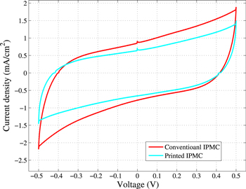
Figure 10. Cyclic voltammograms of a printed and a conventional IPMC, where the voltage was cycled between −0.5 to 0.5 V at a rate of 50 mV s−1.
Download figure:
Standard image High-resolution imageThe double layer capacitance Cd of the printed and conventional IPMCs can be determined by

where  and
and  are the current densities at 0 V and dV/dt is the cycle scan rate [41, 42]. Using equation (1) and the measured current densities, the double layer capacitances of the conventional and printed IPMCs were found to be 67 and 49 mF, respectively.
To test the electromechanical performance of these same IPMCs, they were then driven with periodic voltage signals while their tip displacements were recorded. The IPMCs were driven in distilled water. First, qualitative results showing the bending performance of a sample 3D-printed IPMC are illustrated in the photographs shown in figure 11. Figure 11(a) shows the deflection of the printed IPMC to a −3 V input, figure 11(b) shows the equilibrium position of the printed IPMC given zero input, and figure 11(c) shows the deflection of the printed IPMC to a +3 V input. Second, the measured time responses of the actuation performance are shown in figure 12. The results were obtained where an insulated Kelvin clip, which has electrically isolated sides, was used to fixture the IPMCs and to make electrical contact with the fixtured regions of the electrodes. A Keyence LK-031 laser displacement sensor was used to measure the deflection of the tip of the IPMC actuators. Matlab xPC target system equipped with a National Instruments PCI-6221 data acquisition card was used to log the input and sensor signals. A custom built voltage/current amplifier was used to drive the IPMC sample [43]. The response was obtained for both printed and conventional IPMCs to sinusoidal and square wave input signals at frequencies of 10, 50, 100, 500 mHz, 1, and 5 Hz and voltage amplitude varied between 0.5 to 3 V in 0.5 V increments for each of these frequencies. The results from these tests are summarized in figure 12. Figures 12(a1) and (a2) show the time response of the printed and conventional IPMCs, respectively, to 2.5 V, 100 and 50 mHz sinusoidal inputs. Figures 12(b1) and (b2) show the time response of the printed and conventional IPMCs, respectively, to 2 V square wave inputs at 50 and 10 mHz. Figures 12(c1) and (c2) show the maximum tip deflection of the printed and conventional IPMCs, respectively, in response to square wave inputs over a range of frequencies and amplitudes.
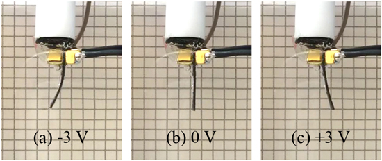
Figure 11. Actuation results: (a) the deflection of the printed IPMC to a −3 V input. (b) The equilibrium position of the printed IPMC given zero input. (c) The deflection of the printed IPMC to a 3 V input.
Download figure:
Standard image High-resolution image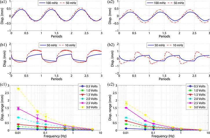
Figure 12. Actuation results for 3D printed IPMC actuator: (a1) time response of a 3D printed IPMC to 2.5 V at 100 and 50 mHz sine wave inputs. (a2) Time response of a conventional IPMC to 2.5 V at 100 and 50 mHz sine wave inputs. (b1) Time response of a 3D printed IPMC to 2 V at 50 and 10 mHz square wave inputs. (b2) Time response of a conventional IPMC to 2 V 50 and 10 mHz square wave inputs. (c1) Range of responses of a 3D printed IPMC to different square wave inputs. Error bar range is one standard deviation. (c2) Range of responses of a conventional IPMC to different square wave inputs. Error bar range is one standard deviation.
Download figure:
Standard image High-resolution image
As can be seen in figures 12(a1) and (a2), the 3D printed IPMC exhibits a somewhat superior response to the conventional IPMC, at lower frequencies. In response to a 10 mHz, 2.5 V amplitude sine wave, the printed IPMC exhibits a maximum tip displacement of approximately 0.57 mm, whereas the conventional IPMC exhibits a maximum tip displacement of only 0.51 mm. The printed IPMC exhibits a maximum displacement of 0.47 mm in response to a 100 mHz, 2.5 V amplitude sine wave, whereas the conventional IPMC exhibits a maximum displacement of 0.37 mm. As can be seen by the square wave response of the IPMCs, shown in figures 12(b1) and (b2), the printed IPMC exhibits a slower response and a slower back relaxation effect than the conventional IPMC. In response to a 10 mHz square wave input, it takes the printed IPMC approximately 6 s to rise to 50% of its maximum deflection. It falls below that same level after approximately 50 s. By contrast, it takes the conventional IPMC approximately 1 s to rise to 50% of its max deflection in response to the same input. It falls below this level after approximately 24 s.
Based on the experimental results, the performance of a 3D-printed IPMC actuator was similar to the performance of an IPMC actuator fabricated from commercially available Nafion sheet stock. Thus, these results demonstrate the functionality of the 3D printing process to create operational IPMC actuators.
4. Conclusions
This paper presented a fused filament AM (3D printing) technique to create IPMC structures. A custom-designed 3D printer was described that utilizes custom-extruded Nafion precursor filament. For the first time, the unique actuation and sensing properties of IPMCs were exploited and directly incorporated into the structural design. Experimental results were presented to demonstrate a functioning IPMC actuator fabricated via the 3D printing process. The performance of a 3D-printed IPMC actuator was characterized and experimental results show similar performance as IPMC fabricated from commercially available Nafion sheet stock. The proposed 3D manufacturing technique can be used to create sub-millimeter scale cilia-like actuators and sensors to macro-scale soft robotic systems. Future work will consider tuning and optimization of the 3D printing process and the manufacturing of more complex 3D structures for application in soft robotics.
Acknowledgments
Authors acknowledge financial support, in part, from the Office of Naval Research, grant number N00014-13-1-0274. Authors also thank Prof Kwang J Kim and Dr Viljar Palmre for their time during technical discussions.