

Abstract
Digital image correlation (DIC) is a widely used technique in experimental mechanics for full field measurement of displacements and strains. The subset matching based DIC requires surfaces containing a random pattern. Even though there are several techniques to create random speckle patterns, their applicability is still limited. For instance, traditional methods such as airbrush painting are not suitable in the following challenging scenarios: (i) when time available to produce the speckle pattern is limited and (ii) when dynamic loading conditions trigger peeling of the pattern. The development and application of some novel techniques to address these situations is presented in this paper. The developed techniques make use of commercially available materials such as temporary tattoo paper, adhesives and stamp kits. The presented techniques are shown to be quick, repeatable, consistent and stable even under impact loads and large deformations. Additionally, they offer the possibility to optimise and customise the speckle pattern. The speckling techniques presented in the paper are also versatile and can be quickly applied in a variety of materials.
Export citation and abstract BibTeX RIS

Original content from this work may be used under the terms of the Creative Commons Attribution 4.0 license. Any further distribution of this work must maintain attribution to the author(s) and the title of the work, journal citation and DOI.
1. Introduction
Digital image correlation (DIC) is a non-contact image-based method for full-field measurement of shape, displacement and deformation [1]. The basic principle of this technique is the comparison of an image of a deformed object to a reference with the purpose of outputting the full field of in-plane [2, 3], out-of-plane [4, 5] or volumetric [6] deformations. DIC has become a widely used technique in experimental mechanics as it allows to measure strains and displacements in a relatively simple manner without the need to physically attach any sensor on the specimens. DIC algorithms require the sample surface to have random intensity variations as a carrier of deformation information. In case the material does not have evident discernible natural texture, biological tissues for instance [7, 8], a random speckle pattern must be artificially created.
A good speckle pattern should meet the following requirements:
- Random enough to ensure having distinguishable patterns at different regions.
- Speckles should have an average size of 3–7 pixels in the acquired image [9].
- Pattern should simultaneously stretch as much as the surface underneath without cracking before the testing material fails.
- Pattern should not affect the mechanical properties of the material under study.
- Pattern should show good adherence and not detach from the surface during the test.
It is generally difficult to create a speckle pattern that meet all these requirements and it is even more challenging if the testing conditions or the sample pre-conditioning impose time restrictions in the procedure or have high adhesion requirements due to dynamic loads during testing. Even though newly developed DIC algorithms can handle sensor image noise and blurriness better [10], speckle patterns with high contrast, randomness, isotropy and stability are still paramount to obtain good results.
There are several techniques such as spin coating, lithography, focused ion beam (FIB), etc that are used to create random speckled patterns, but the most common technique is spray painting using an airbrush or spray can [11]. Typically, black paint is sprayed on a white background to create a high contrast speckle pattern [12, 13], though it is also possible to simply spray white speckles if the specimen is dark enough to provide enough contrast. Spray painting, despite its broad applicability, have some limitations. Even though spray painting is quick and easy, the technique is inconsistent because of variability in the size and distribution of speckles. The speckle size distribution when a spray bottle or an airbrush is used depends on parameters such as the nozzle diameter, the distance between the substrate and the nozzle, air pressure and viscosity of the solution. The technique is also operator dependent and can produce different speckle patterns even under the same procedure.
Another limitation of this technique is that creating a speckle pattern normally requires time for the paint to dry. In certain cases, the time available to apply the speckle pattern to the sample is limited. For example, according to the standard ASTM D618 [14], hygrothermally pre-conditioned polymer or composite coupons, such as those used to investigate effects of moisture [3, 15], should be tested within 30 min of having been removed from their pre-conditioning environment. Beyond that time, the exposure with the room conditions will affect or invalidate the pre-conditioning.
Finally, spray painting generally produces fine speckles, which may be too small for large plate experiments, where the region of interest (ROI) can be in the order of 100 mm x 100 mm or larger; therefore, traditional spraying cannot provide speckle sizes that meet the recommendations given by Sutton et al [9]. Although manual speckling using a marker appears to be a solution to creating speckle patterns for large specimens, it is generally time consuming and labour intensive. Thus, there is a need for techniques capable of efficiently generating speckle patterns with different average speckle sizes.
Another critical element for a successful DIC measurement is the adhesion of the speckle pattern to the test specimen. From our own experience, high-speed impact loads tend to cause peeling of the paint even at low strains making DIC analysis impossible. Therefore, a procedure that guarantees a strong adhesion of the background paint at extreme dynamic loads is needed.
Different researchers have tried to overcome problems related to consistent and quick speckling. Zhang et al [16] proposed and evaluated a novel method using an atomization system to repeatedly generate speckle patterns. Hu et al [17] developed a laser engraving technology to create speckles with controllable size, density, depth and distribution of the speckles. Pankoinen et al [18] investigated the efficacy of including patterns in 3D-printed parts for non-contact strain measurement for digital image correlation. Jannotti and Schuster [19] developed a 3-axis mill with a custom-made, spring-actuated permanent marker holder to produce automated, high-quality, and consistent speckle patterns that can be tailored for the specific requirements of the testing. However, while these techniques solve the problem of consistent speckling, they are still time consuming or limited in their applicability. Ashrafi and Tuttle [20] used a speckled pattern printed on paper using a standard laser printer and then bonded to the surface of the test specimen using a common strain gage adhesive. Chen et al [21] proposed a controllable speckle creation method based on water transfer printing (WTP) where a water-soluble slip layer dissolves and leaves the printed speckle pattern part on the carrier's surface. However, their technique still requires surface preparation (white base painting) if the material does not have enough contrast with the speckle, which increases the specimen preparation time. Speckle patterns using customisable transfer paper represent the possibility of a significant step in the quality control of DIC for a range of materials and applications [22].
In this paper, we present two case studies where novel speckling techniques were developed and applied to quickly prepare the specimen for testing and to endure impact loads. The first technique, described in section 2, employs a temporary tattoo technique to transfer a custom-designed speckle pattern on pre-conditioned composite samples used in high rate characterisation tests. The versatility of this speckling technique on other substrates was also demonstrated in the case of a quasi-static test of an aluminium alloy. In the second case study, presented in section 3, a stamping technique was used to create speckled patterns that can firmly adhere to large composite plates used in ballistic impact tests.
2. 'Tattoo' speckle pattern
2.1. Materials and preparation
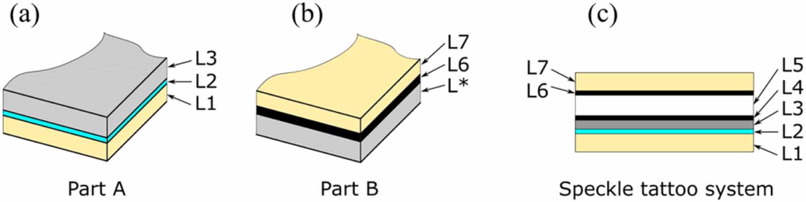
The proposed solution made use of a temporary tattoo or water slide paper. Tattoo paper is normally used to create custom-printed temporary tattoos. It is commercially available in different sizes and two main types, laser or inkjet, depending on the printing method to be used. In this work, we used an A4 sized laser tattoo set. The commercial tattoo sets consist of two parts: Part A or main canvas composed by layers L1, L2 and L3 as shown in figure 1(a); and Part B, containing layers L*, L6 and L7 as shown in figure 1(b). Layers L4 and L5 layers were added as explained in the procedure below. The final layup of the system is shown in figure 1(c). A summary and a brief description of all layers are given in table 1.
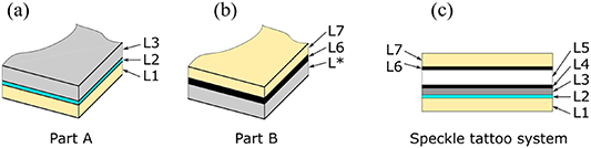
Figure 1. Through thickness views of: (a) part A, (b) part B of the temporary tattoo paper set; and (c) the final layup of the 'tattoo' speckle system.
Download figure:
Standard image High-resolution imageTable 1. Layers in the 'tattoo' speckle pattern system.
| Layer | Description | Origin |
|---|---|---|
| L1 | Base (water absorbent paper) | Part A |
| L2 | Water soluble layer | Part A |
| L3 | Transparent layer (glossy side) | Part A |
| L4 | Laser Printed layer (speckle) | Laser printed |
| L5 | Sprayed white painting | Manually sprayed |
| L* | Protective layer | Part B |
| L6 | Sticky film | Part B |
| L7 | Protective layer | Part B |
The complete procedure to produce the 'tattoo' speckle pattern system is displayed in figure 2 and detailed in the following steps:
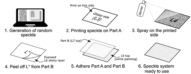
Figure 2. Steps to create the 'tattoo' speckle pattern.
Download figure:
Standard image High-resolution imageStep 1: Design and create the speckle pattern, as described in section 2.2.
Step 2: Create layer L4 by printing the pattern on the glossy side of Part A (layer L3). We used the Ricoh Aficio MP C3502 M laser printer.
Step 3: Spray white painting on L4 layer with an airbrush and let dry. We used Magic Color (West Design, United Kingdom) liquid acrylic white painting.
Step 4: Remove layer L* from part B, exposing the adhesive layer L6.
Step 5: Adhere L6 side of part B to L5 (white painting) layer. We recommend the use of a rigid ruler to prevent or minimise air pockets.
Step 6: Speckle system is ready to be used and the final layup should be L1, L2, L3, L4, L5, L6, L7 (figure 1(c)).
Once the 'tattoo' speckle pattern system was created, the procedure to apply it on the specimen was as follows (see figure 3):

Figure 3. Steps to apply the 'tattoo' speckle on the specimen.
Download figure:
Standard image High-resolution imageStep 1: Use scissors to cut the required surface area from the 'tattoo' speckle pattern system.
Step 2: Remove protective layer L7, exposing the sticky layer L6.
Step 3: Stick the 'tattoo' speckle to the cleaned surface of the specimen.
Step 4: Using a wet cloth or brush, wet the Base layer L1 for few seconds. Due to rapid diffusion of water, the soluble layer L2 gets dissolved and L1 slides off, exposing the pattern. The specimen is then ready to test.
2.2. Pattern design and generation
One of the most important features of the pattern is the speckle size, which depends on the size of the ROI and the setup used to acquire the images (camera sensor size, focal length, etc). For example, for our quasi-static experiment, we used a 60 mm Nikon lens mounted to a JAI camera via a C-mount adapter. For such configuration, the pictures had a resolution of ∼0.043 mm/pixel, calculated from a picture with the given setup and a comparison against a known dimension in the photograph. Therefore, for a required ideal particle size of 5 pixels (section 1), a speckle size of ∼0.22 mm is required.
Two different methods to generate the pattern were followed. A first random pattern was made with the software ImageJ v1.52 a [23]. A 797 × 1122 pixels white image canvas was created. Grayscale noise was generated with the built-in function add specified noise set to a standard deviation of 50 [24]. The resulting image was binarized to obtain a speckle pattern with the maximum contrast possible, followed by dilate built-in function to increase the speckle size. The generated image was copied into an A4 canvas on Inkscape v0.92.3 [25], where it was re-scaled such that the speckle would be captured by the camera setup with a size of ∼3-7 pixels.
The second random pattern was created the software Speckle Generator from Correlated Solutions [26]. This software lets the user specify canvas size, diameters and aerial fraction. Particles with diameter of 0.22 mm and 50% density were created on an A4 canvas size (297 mm x 210 mm).
The images acquired during the tests confirmed that the speckle obtained with both methods met the size requirements.
2.3. Mechanical experiments
The first test was performed on a 2.6 mm thick glass fibre reinforced polymer (GFRP) tensile specimen with [45]8 layup under impact loading, conducted on a Split Hopkinson Bar. This specimen was part of an experimental campaign aiming to characterise the effects of hygrothermal ageing upon glass fibre composites [27]. The Split Hopkinson bar provides with a travelling stress wave, generated by a striker, and is used for high strain rate testing. The specimen geometry is shown in figure 4(a) and was prepared with the first type of generated pattern. More details on the Split Hopkinson bar setup used in this experiment can be found in references [2, 3, 27]. The history of strains were measured via DIC analysis of high speed images, which were acquired with the Kirana high speed camera (Specialised Imaging Ltd, UK) at 400 000 fps with a resolution of  pixels. The images were analysed with the Software GOM Aramis v6.7 [28], with facet and step size of 21 and 17 pixels, respectively.
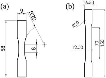
Figure 4. Geometry of specimens: (a) GFRP coupon for high strain rate experiment; (b) Aluminium specimen for quasi-static experiment.
Download figure:
Standard image High-resolution imageTo prove the applicability of this method on other materials and testing configurations, a standard aluminium sample was also prepared (see figure 4(b)). This coupon was quasi-statically tested under the Zwick Z250 screw-driven machine with a prescribed crosshead speed of 1 mm min−1. Photographs of resolution  pixels were taken during the test at a rate of 1 fps with a JAI camera. Those images were analysed with the Software GOM Aramis v6.7 [28], with facet and step size of 21 and 17 pixels respectively.
2.4. Results and discussion
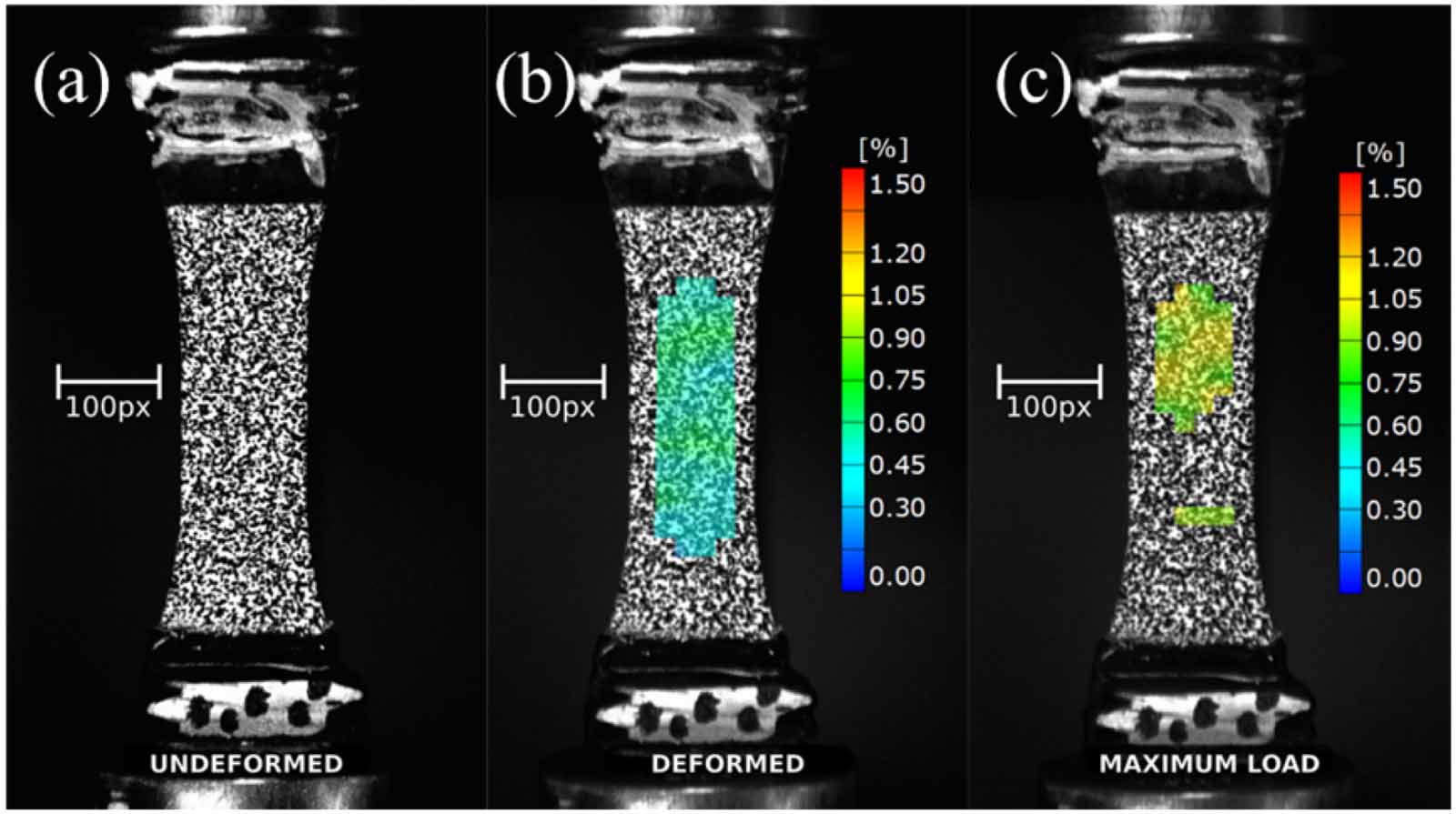
The resulting speckle pattern on the composite specimen is shown in figure 5. The quality of the speckle pattern was verified using the metric mean intensity gradient (MIG). An MIG value of 81.6 was calculated for the speckled region of interest (only a section of figure 5(a)). Pan et al [29] compared the mean bias error and standard deviation error of speckled patterns with MIG ranging from 9 to 35 and concluded that a higher MIG correlated with a smaller error. A mean bias error of displacement less than 1% was reported for MIG values greater than 20 [29] and the relatively high value of MIG indicates that the speckled pattern is of good quality for DIC.

Figure 5. Tensile GFRP specimen under high strain rate testing (Hopkinson bar test) maintains the integrity of the speckle: (a)Undeformed, (b) Deformed, and (c)Maximum load.
Download figure:
Standard image High-resolution imageThe 'tattoo' speckle pattern appears to remain intact during the test (figure 5), and to break only when specimen fractures at maximum load. The results of the calculated local engineering strains in the centre of the specimen are displayed in figure 6. Curve shows a smooth increase of the strain during the test which means that no discontinuity on the speckle (cracking) took place during the experiment. Every 25 μs, a small drop in the strain can be observed, which given the framerate, corresponds to the time between ten pictures. The origin of this noise is intrinsically associated to the optical sensor of camera we used, as we have observed the same effect every ten pictures with other specimens, different framerates and using classic sprayed patterns.
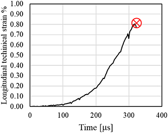
Figure 6. History of technical axial strains in the GFRP high strain rate test.
Download figure:
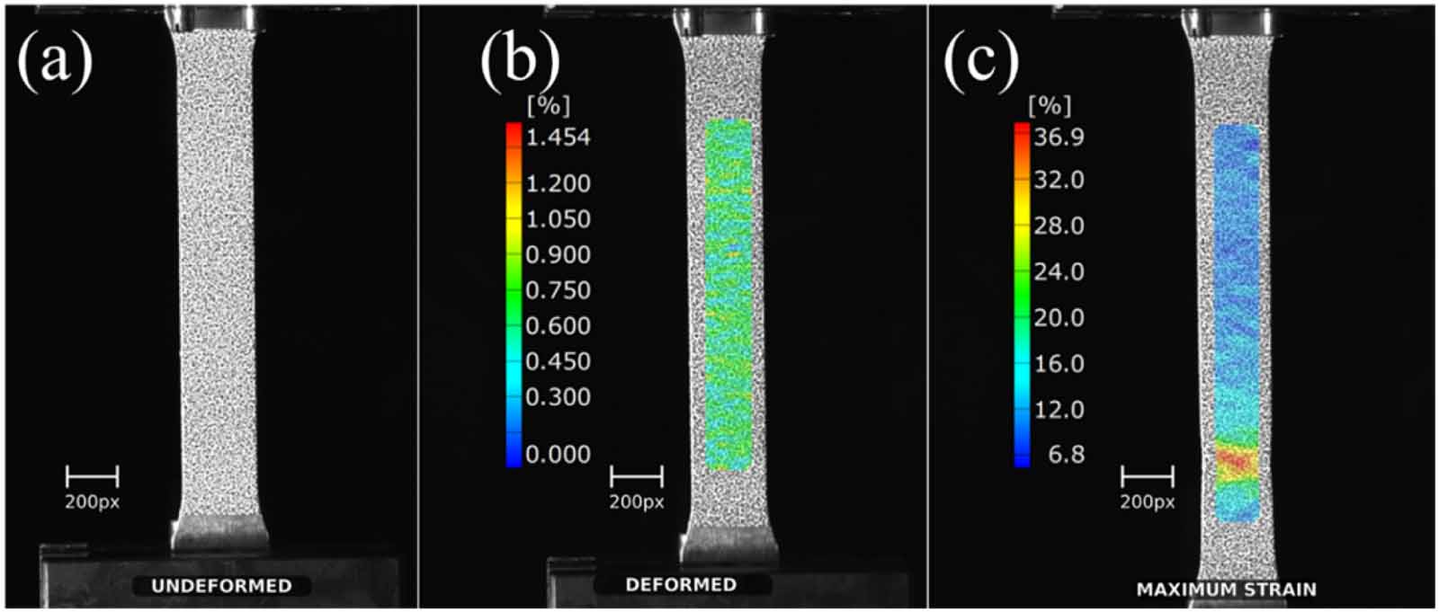
Standard image High-resolution imageThe experiment with the aluminium specimen and the second type of pattern is shown in figure 7. The MIG calculated for the speckled region of interest was 25.92, confirming good quality according to the range reported in [29]. The uniform strain field observed in the deformed image (figure 7(b)) shows the good adhesion that the 'tattoo' speckle provides. Even at the maximum deformation of 37% (figure 7(c)), the pattern did not show any signs of cracking or detaching. Figure 8 shows the history of technical strains calculated at a point inside the necking region. Again, the calculated strains show a smooth evolution up to breakage.
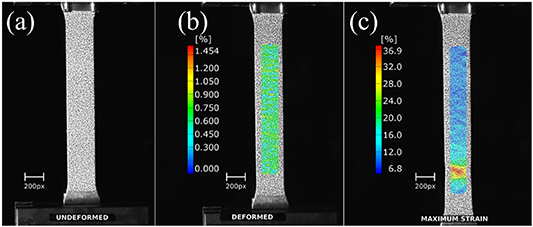
Figure 7. Tensile aluminium specimen under quasi-static loading maintains the integrity of the speckle during the test: (a) Undeformed, (b) Deformed, and (c) Maximum strain.
Download figure:
Standard image High-resolution image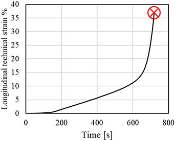
Figure 8. History of technical axial strains in the aluminium quasi-static tensile test.
Download figure:
Standard image High-resolution imageIn both experiments, during deformation, (figures 5(b) and 7(b)) the field of longitudinal strain is also approximately homogeneous, which demonstrates good adherence and stretchability of the 'tattoo' speckle system.
As shown above, the 'tattoo' speckle pattern has proved to be a fast and reliable solution, for composite and metallic specimens. It withstood large deformations and impact loads, without cracking or detaching. This technique allows to pre-design and customise the speckle pattern, to optimise the distribution and pattern size that can highly improve the results obtained with DIC [30]. Unlike the WTP method introduced by Chen et al [21], the 'tattoo' speckle system already contains a white background. This considerably reduces specimen preparation time, which in certain cases can be critical for the experiment.
3. Impact testing of composite panels
3.1. Setup of ballistic impact testing and stereo-DIC analysis
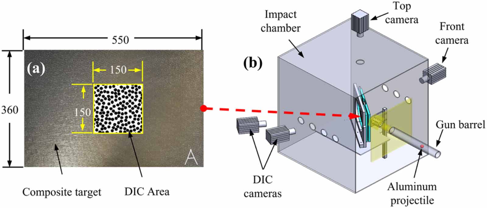
The second part of this paper discusses some challenges encountered in the application of DIC technique to evaluate the performance of composite specimens subjected to ballistic impact. Carbon fibre-reinforced polymer (CFRP) composite plates with dimensions of 550 mm × 360 mm × 10 mm were chosen for this study. Figure 9(a) shows a typical CFRP plate used in the ballistic impact testing, where the central area of interest (150 mm × 150 mm) of the non-impact (rear) side was painted in white and marked with randomly distributed black speckles for DIC analysis. In each test, the plate was clamped in a fixture and impacted by an aluminium projectile at an initial velocity of approximately 200 m s−1 using a single-stage gas gun, as schematically shown in figure 9(b). Two DIC cameras (Photron FASTCAM SA5, Photron Ltd, Japan) were positioned on the non-impact side to record the DIC area, and the recorded images ( pixels) were used to conduct stereo-DIC analysis to obtain full-field data of the target area, including out-of-plane displacements. Stereo DIC requires calibration, for which a special rig was designed and built (see figure 10). Additionally, two high speed cameras (top and front) were used to observe the impact event, but not for the DIC analysis.
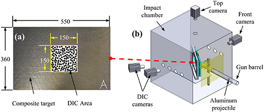
Figure 9. Ballistic impact test of CFRP panels on a gas gun: (a) the DIC side of the specimen panel with speckle pattern; (b) schematic of the whole test setup.
Download figure:
Standard image High-resolution image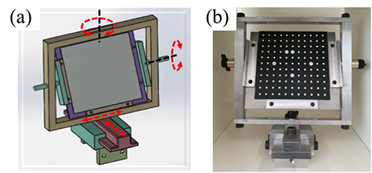
Figure 10. In-house stereo-DIC calibration rig: (a) CAD model, (b) manufactured rig.
Download figure:
Standard image High-resolution image3.2. Improvement of adhesion
A thin layer of primer Ambersil satin finish galvanised paint (CRC Industries, United Kingdom) was sprayed on the composite surface to form a white background for the DIC area. The first challenge originated from the relatively brittle primer which has a low surface adhesion strength on composites. The paint layer could not firmly adhere to the panel surface and deform simultaneously during ballistic impact and the resultant images were unsuitable for DIC analysis. As shown in figures 11(a)–(b), the spalling of the paint destroyed the speckle pattern in the central region, even though there was not significant deformation or damage in this region. This resulted in a partial loss of data in the displacement contour, as well as in the distributions of displacements along the two sections of interest, figure 11(c).
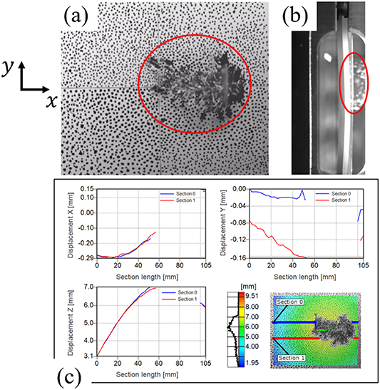
Figure 11. Impact test of the plate without our improved procedure. The primer paint peeling off from the panel: (a) the DIC camera view, (b) the top camera view and (c) DIC post-processed results along sections 0 (blue) and 1 (red) showing significant area with no measured strains.
Download figure:
Standard image High-resolution imageThis problem of poor adhesion of the paint to the composite surface was overcome by applying a thin base layer of 3M Epoxy Adhesive DP460 (Clear) before applying the primer paint. The procedure for applying the epoxy base layer was as follows:
Step 1: Clean the surface area to be painted with Degreaser Loctite 7063 and let it dry;
Step 2: Apply some 3M Epoxy Adhesive DP460 on the surface area and spread the adhesive using a blade scrapper to form a thin, even layer of epoxy resin;
Step 3: Wait 30 min to let the adhesive cure partially;
Step 4: Spray a thin layer of Ambersil Satin Finish Galvanised Paint (White) onto the partially cured adhesive layer to create a white background;
Step 5: Wait 48 h to let the adhesive cure fully.
The problem of the primer paint peeling off, caused by the impact load and surface deformation, was eliminated completely by adding the additional layer of 3M epoxy resin. Figures 12(a)–(b) show two images recorded in a typical impact test implementing the proposed procedure. Here, it is evident that the primer paint firmly adhered to the DIC side of the panel during the impact event despite the presence of large cracks.
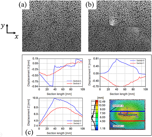
Figure 12. Impact test of the CFRP plate with improved adhesion of the speckle. (a) Image at start of impact, (b) image at peak out-of-plane deformation of impact and (c) post-processed DIC results showing better acquisition of displacements along sections 0 (blue) and 1 (red).
Download figure:
Standard image High-resolution imageThe validity of the proposed method can be further confirmed by taking a closer examination of the DIC-processed results, shown in figure 12(c), where blue and red lines represent the measurements along sections 0 and 1 respectively. There is a distinct difference in the y-displacements along Sections 0 and 1, with the corresponding curves being primarily on the positive and negative sides, respectively. This agrees with the fact that the projectile impacted the non-speckled side of the panel (out of the page or z-direction), causing the material along Sections 0 and 1 to move away from the horizontal crack towards the + y and -y directions, respectively. The DIC results also suggest that the Z-displacement along Section 0 was higher than that along section 1, which again agrees with the fact that the material above the horizontal crack was in a higher degree of deformation than the material below the crack, figure 12(b). Based on the above analysis, it is established that the proposed method is effective in addressing the problem shown in figure 11.
3.3. Speckling large panels
Another challenge arises from the need of generating speckles with an average diameter of 1 mm to meet the requirement of having an average speckle size of 3–7 pixels. As the area of the DIC region was 150 mm × 150 mm, generating 5000−10 000 speckles per plate was needed. Clearly, this speckle size was neither fine enough to be created by spraying nor big enough by using stencils. The obvious alternative to produce speckles of required diameter was to manually mark the samples using a permanent marker. However, it was found to be overly time-consuming − the average time for marking the DIC area of the composite plate was ∼1.5 h.
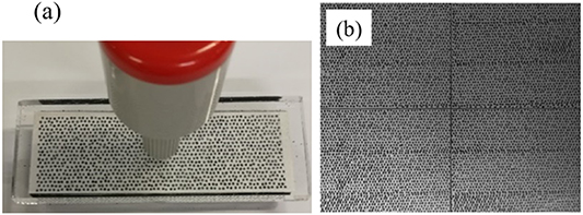
It has been reported that generating speckle patterns for large specimens can be addressed by using a customised metal stencil [31] or a combination of a CNC 3-axis mill and a permanent marker [19]. However, machining a metal stencil that meets the requirement of generating 5000−10 000 randomly distributed speckles in an area of 150 mm × 150 mm is overcomplex. On the other hand, utilising a CNC 3-axis mill with a marker is also impractical and expensive considering the number of speckles on each plate and the number of plates to be speckled. In the present research, the efficiency problem in generating speckles was addressed by using Imetrum's specimen marking stamps (Imetrum Ltd., UK) [32]. By using the 1.1 mm stamp (figure 13(a)), the efficiency for generating random speckle patterns with the required speckle size for an area of 150 mm × 150 mm was significantly improved, from originally 1 ∼ 1.5 h to only few minutes. It is relevant to note that the round tips on the stamps exhibit some flexibility, allowing the user to create a slightly different pattern each time (as shown in figure 13(b)) by pressing the stamp with a different pressure and a small movement in directions parallel to the DIC surface. In addition, it is recommended to apply the stamp at the same place for multiple times to increase the randomness of the speckling pattern. These recommendations are useful to address a limitation of using stamps, which tends to create similar sub-patterns in a large specimen and reduces the overall randomness of the whole pattern.
Figure 13. (a) The 1.1 mm Imetrum stamp. (b) Typical stamped speckle pattern.
Download figure:
Standard image High-resolution image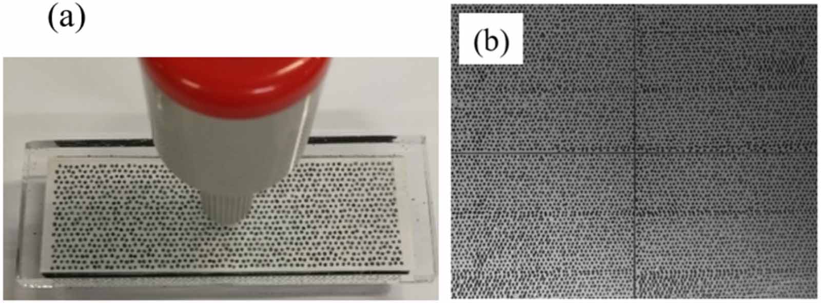
The qualities of the speckle patterns generated using a permanent marker (figure 12(a)) and the proposed stamping approach (figure 13(b)) were again characterised with the MIG method. MIG values of 32.2 and 31.7 were obtained for the two speckle patterns, respectively, higher than the threshold of set out in [29]. Therefore, the speckle patterns can be considered of good quality and to provide small errors in the DIC measurements.
4. Conclusions
The accuracy of the DIC results is highly dependent on the quality of the speckle pattern. This paper proposed practical, innovative, easy to implement and low-cost solutions to challenging situations when speckle patterns cannot be obtained by traditional methods. The procedures were described in detailed and the produced patterns were analysed qualitatively and quantitatively. The main conclusions are:
- Commercially available temporary tattoo can be used to create high quality, customised and optimised 'tattoo' speckle patterns that allow for quick application on specimens.
- The versatility of the 'tattoo' speckle was successfully demonstrated in two different materials (GFRP and aluminium) and loading regimes (quasi-static and high strain rate) displaying good adhesion and the ability to withstand large strains.
- A combination of thin epoxy adhesive layer and speckle stamping was found to be an effective and time-saving solution for impact tests of large composite panels, where patterns created with more traditional techniques would normally peel-off under dynamic loads.
Acknowledgments
This project was supported by EPSRC, Dstl, Rolls-Royce plc (grant EP/G042586/1), and UKRI (grant 113106). Authors would like to thank Mr Jeff Fullerton and Mr Stuart Carter for their valuable support with manufacturing, and Mrs Karen Bamford for her immense help to get our purchase orders on time.