

Abstract
A target application of wearable sensors is to detect human motion and to monitor physical activity for improving athletic performance and for delivering better physical therapy. In addition, measuring human vital signals (e.g., respiration rate and body temperature) provides rich information that can be used to assess a subject's physiological or psychological condition. This study aims to design a multifunctional, wearable, fabric-based sensing system. First, carbon nanotube (CNT)-based thin films were fabricated by spraying. Second, the thin films were integrated with stretchable fabrics to form the fabric sensors. Third, the strain and temperature sensing properties of sensors fabricated using different CNT concentrations were characterized. Furthermore, the sensors were demonstrated to detect human finger bending motions, so as to validate their practical strain sensing performance. Finally, to monitor human respiration, the fabric sensors were integrated with a chest band, which was directly worn by a human subject. Quantification of respiration rates were successfully achieved. Overall, the fabric sensors were characterized by advantages such as flexibility, ease of fabrication, lightweight, low-cost, noninvasiveness, and user comfort.
Export citation and abstract BibTeX RIS
1. Introduction
Wearable sensors are transducers that can be externally applied onto individuals and provide signals related to human physiological parameters [1]. They have received extensive attention mainly due to their potential for improving the well-being of diverse groups. For example, people working in dangerous or harsh environment (e.g., soldiers, firefighters, and astronauts) are faced with a variety of potentially life-threatening situations. Wearable sensors can enable real-time monitoring of their physiological performance for ensuring safety. In addition, in the context of senior care, wearable sensors-assisted health monitoring systems enable senior citizens and patients to receive diagnosis or treatment without physically visiting a hospital and to receive care in a more hospitable environment, such as their own home, which is the goal of the telemedicine movement [1, 2]. When it comes to enhancing athletes' performance, wearable sensors offer tremendous opportunities for better quantifying and analyzing their motions, which, at the same time, can help protect them from injuries [3]. Given the broad impacts of wearable sensors, it is imperative to further develop higher performance transducers that can monitor different aspects of human performance, such as physical motions and human vitals, among others.
A popular approach of designing wearable sensors is to integrate commercial-off-the-shelf electronic devices, including strain gages, accelerometers, and pulse-oximeters, among others, to form a miniature hardware package. Some examples of early-generation wearable sensors were designed as rings, glasses, bracelets, and watches. For instance, a ring sensor equipped with light-emitting diodes and photo-detectors was developed by Rhee et al [4] for wirelessly monitoring patients' blood oxygen saturation. Anliker et al [5] designed a portable telemedical monitoring and alerting system that could be worn on the wrist of patients whom suffer from cardiac/respiratory diseases. The sensing system can monitor a variety of vital signals, including heart rate, blood pressure, electrocardiogram (ECG), and skin temperature. Further developments sought to incorporate these sensors in clothes and garments for minimizing the inconvenience of having to wear additional peripheral devices on one's body. Gopalsamy et al [6] presented a smart shirt integrated with a 'wearable motherboard' that can be easily worn by soldiers for monitoring multiple vital parameters. Pandian et al [3] designed a smart vest, which was equipped with temperature sensors, electrodes for ECG, photoplethysmograph, and galvanic skin response measurements. Lee et al [2] used a smart shirt coupled with a wireless sensor network to accurately extract ECG signals from a test subject's physical movements. One of the considerable advantages of these conventional wearable sensing systems is that a single sensor can be used to measure multiple physiological parameters with favorable accuracy. Besides, many of the sensors are relatively low-cost. However, these devices usually include bulky and rigid components. Their form factors and intrinsic rigidity can be incompatible with complex and high-strains typical of human motions, which can not only compromise sensing accuracy but can also cause user discomfort.
As the demands for flexible wearable sensors have increased in recent years, a plethora of nanomaterials have been identified as promising candidates to design sensors that could replace those aforementioned, bulky, rigid transducers [7]. By leveraging their extraordinary mechanical, electrical, and chemical properties, highly flexible and sensitive wearable sensors have been developed for monitoring various bio-signals [8, 9]. For example, Yamada et al [10] grew carbon nanotube (CNT) forests onto poly(dimethyl siloxane) (PDMS), which functioned as the flexible substrate. The assembled device could be attached to different human body parts, and the strains generated at those regions can change the configuration of the CNT forest to cause corresponding detectable electrical resistance variations. Wang et al [11] transferred graphene grown by chemical vapor deposition to PDMS and medical tape. The resulting device showed high strain sensitivity potentially suitable for monitoring small human motions. Besides graphene and CNTs, nanowires (NW), such as silver NWs [12] and gold NWs [13], were also employed for fabricating devices for monitoring human physical movements. On the other hand, human skin-inspired e-skins were also investigated [8, 9]. Pang et al [14] developed a laminated patch-like sensor, in which nanofibers were mechanically interlocked. External forces could change the configuration of the nanofibers, and, hence, the electrical resistance would be altered accordingly. When attached to the waist, the sensor was sensitive enough to detect heartbeat. Kwak et al [15] designed a skin patch with nanostructured micro-hairs, which allowed for dry attachment onto the human chest for ECG monitoring. Other nanomaterial-based wearable sensors also exhibited additional advantages, such as being transparent [16, 17], self-powered [17, 18], and self-healing [19]. Despite these tremendous advancements, they generally required complicated fabrication procedures and are limited in scalability and cost efficiency.
Therefore, in an effort to overcome the limitations in current wearable sensor designs, the objective of this study was to develop and characterize a multifunctional, wearable, fabric-like sensor for monitoring human physiological performance. The target parameters to quantify included human motions, body temperature, and respiration rate. Here, CNTs were selected as the sensing element for their excellent mechanical [20, 21] and electrical properties [22, 23]. In addition, previous work showed that CNTs could be effectively integrated in a scalable spray-coating process to deposit thin film strain sensors in a time- and cost-efficient manner [24, 25]. This paper begins with a description of wearable sensor design, including the spray-fabrication procedure and how they could be integrated with flexible fabric. Since human motions and respiration can be monitored by measuring strain, the fabric-based sensors were subjected to tensile cyclic load tests. On the other hand, the sensors' temperature sensing properties were also investigated for body temperature monitoring applications. The test results are discussed, and validation of human monitoring was performed by demonstrating the detection of finger motions and the respiration process.
2. Experimental details
2.1. Materials
Multi-walled carbon nanotubes (MWCNT) were from SouthWest NanoTechnologies (outer diameter: 6–9 nm; length: ∼5 μm; purity ≥ 95%). Poly(sodium 4-styrenesulfonate) (PSS) (molecular weight: ∼ 1 M) and N-methyl-2-pyrrolindinone (NMP) were acquired from Sigma–Aldrich. Latex solution was from Kynar Aquatec. Fabrics, such as 100% nylon knitted and 100% polyester woven fabrics, were utilized for sensor fabrication. The Heatnbond double-sided iron-on adhesive was from Fabricado par. All materials were used as purchased.
2.2. Fabric sensor fabrication
The fabric sensors utilized MWCNT-based nanocomposite thin films as sensing elements. Here, thin films were fabricated using a spray deposition or airbrushing technique, whose details can be found in Wang and Loh [24, 25]. To be concise, MWCNTs were first dispersed by high-energy probe ultrasonication (3 mm tip, 150 W, 22 kHz) to form an aqueous solution, where 2 wt% PSS and a minute amount of NMP served as dispersing agents. Then, latex solution (as binder for the thin films) and deionized water were added in appropriate quantities to obtain the sprayable ink. A commercial Paasche airbrush was used to spray the ink onto 25 × 75 mm2 glass microscope slides. In order to enhance the mechanical [25] and electromechanical properties [24] of the thin films, they were subjected to thermal annealing after being air-dried for at least 4 h, that is, at 80 °C for 12 h, followed by 150 °C for 3 h. In this study, nanocomposites of different MWCNT concentrations (i.e., 1, 2, and 3 wt%) were fabricated. Scanning electron microscopy (SEM) was employed to characterize the nanostructure of the films. Figure 1(a) shows an SEM image of an annealed 3 wt% thin film, which suggests that MWCNTs were uniformly dispersed, either as individual tubes or small bundles, and were embedded in the polymeric matrix to form a percolated MWCNT network throughout the nanocomposite.

Figure 1. (a) SEM image of an annealed 3 wt% MWCNT-latex thin film. (b) Illustration of the sandwich structure of fabric sensors and photographs of an assembled sensor.
Download figure:
Standard image High-resolution imageAfter obtaining the annealed freestanding thin films, they were used to assemble the fabric sensors. As shown in figure 1(b), electrodes were directly established on both ends of the thin films (gage length: 48 mm). The film was sandwiched between two layers of double-sided iron-on adhesives and fabrics, and then integrated together by ironing (temperature: ∼ 130 °C). Here, ironing was performed manually, or one can use a commercial heat press to ensure consistency. In addition, it should be noted that the ironing temperature used was below the film's annealing temperature and would not adversely affect film properties. Finally, the fabric sensors were cut to form 16 × 132 mm2 smaller specimens for tests. The photographs of an assembled specimen in figure 1(b) indicate that the fabric sensor was highly flexible and that the sandwiched structure was strong enough to undergo large deformations.
2.3. Electromechanical characterization
The strain sensing performance of 1, 2, and 3 wt% fabric sensors was characterized by subjecting them to uniaxial tensile cyclic strains. Figure 2 shows the experimental setup from two different perspectives. Here, a Test Resources 150R load frame was used to apply strain patterns to the specimens, whose electrical resistance was measured using an Agilent 34401A digital multimeter (DMM), and data from the DMM were recorded by a LabVIEW program.
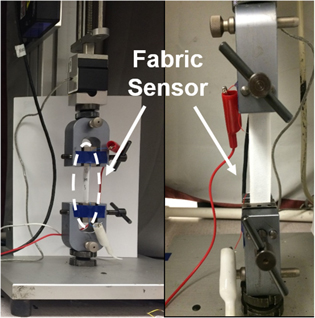
Figure 2. Fabric sensor mounted in the load frame and connected to a DMM for electromechanical testing.
Download figure:
Standard image High-resolution imageDuring each load test, an initial pretension force (0.03 N) was applied to pull the specimen taut. After the film's resistance stabilized, multiple sets of five-cycle tensile strains were applied. To investigate the sensor's performance, different load rate (in % min−1) and peak strain (in %) combinations were applied, including: 0.5% min−1, 1%; 1% min−1, 1%; 1% min−1, 2%; and 2% min−1, 2%. It should be noted that the strain patterns applied here aimed to validate the piezoresistivity of the fabric sensors. When being utilized for monitoring human motions and respiration, the fabric sensors could be subjected to various strain patterns (including strains much higher than 2%), whose sensing performance will be demonstrated later in this paper. All strain sensing tests were conducted in ambient room temperature.
2.4. Temperature sensing characterization
For temperature sensing tests, fabric sensors of different MWCNT concentrations were mounted on a hot plate (Corning PC-620D), which was employed to introduce changes in ambient temperature. A thermocouple (Omega) was also adhered onto the surface of each fabric sensor for measuring its actual temperature change. In addition, two DMMs were utilized to simultaneously record the resistance of the fabric sensor and the thermocouple's direct current (DC) voltage response, which can be converted to temperature values. During each heating/cooling cycle, the temperature of the hot plate was first increased from ∼21 °C to ∼65 °C, after which, it was switched off for the system to cool. Multiple heating/cooling cycles were applied to each specimen. The sensors were not strained during temperature sensing tests.
2.5. Human motion and respiration monitoring
Two sets of tests were conducted. Validation of human motion monitoring was first performed by using a 2 wt% fabric sensor for detecting finger bending movements. To be specific, the fabric sensor was longitudinally adhered onto the index finger of a human subject. During the test, the finger repetitively bent to roughly three different angles, and the sensor's resistance change was recorded by a DMM in real-time.
Second, the fabric sensors were also used to monitor respiration, where the goal was to capture strain changes caused by thorax expansion and contraction during respiration. Here, sensor design was improved by utilizing conductive threads and stainless steel snap buttons for the electrodes, instead of single-strand wires, as shown in figure 3(a). The inset of figure 3(b) shows both sides of the assembled fabric sensor. Here, conductive threads were sewn tightly over the snap buttons to establish reliable electrical contacts. Resistance measurements were obtained using the snap buttons as electrodes. This new sensor design allowed the fabric sensors to be even more flexible. In addition, with the use of snap buttons, sensors can be readily installed onto or disassembled from garments, which enabled the sensors to be reusable.
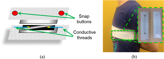
Figure 3. (a) Fabric sensor with conductive threads and snap buttons was (b) attached to a chest band for respiration monitoring.
Download figure:
Standard image High-resolution imageIn the respiration monitoring tests, each fabric sensor was implemented on a customized chest band with snap buttons. The chest band was worn by a human subject, as exhibited in figure 3(b), and the electrical resistance of the fabric sensor was recorded as the subject breathed. To ensure favorable strain transfer from thorax motion to the sensor, the chest band needed to be tight, while the fabric sensor should be taut after installation. In this study, the subject stood still and breathed at roughly even respiration rates, while resistance was measured using a DMM. It should be mentioned that the subject was asked to take deeper breaths, so respiration rate was lower than the typical standard for an adult at rest (i.e., 12–20 breaths min−1).
3. Results and discussion
3.1. Strain sensing response
Fabric sensors of different MWCNT concentrations were subjected to different tensile strain patterns as described in section 2.3. Their strain sensing properties were analyzed based on their resistance time histories. Figure 4 plots the resistance time history of a 3 wt% specimen when subjected to load tests applied using a load rate of 1% min−1 and a peak strain of 1%. It was found that the sensor's resistance changed in a relatively stable and repetitive fashion throughout the load test. Sensors of different MWCNT concentrations exhibited similar performance, regardless of the strain patterns applied. To further investigate the sensors' strain sensing response, the normalized change in resistance (Rn) was calculated using equation (1):

where ΔR and R0 are change in resistance and unstrained resistance, respectively.

Figure 4. Representative resistance time history of a 3 wt% fabric sensor when subjected to multiple sets of five-cycle tensile strain patterns (load rate: 1% min−1; peak strain: 1%).
Download figure:
Standard image High-resolution imageFigure 5(a) overlays a set of representative Rn time histories of 1, 2, and 3 wt% fabric sensors subjected to the same five-cycle strain pattern (load rate: 0.5% min−1; max strain: 1%). It was found that the sensors' resistance became higher when tensile strain was increasingly applied and decreased during unloading, as expected. This was true for all MWCNT concentrations as well as for different strain patterns (not shown here). The observed piezoresistivity was assumed to be a result of strain-induced disturbances to the electrically-conductive, percolated MWCNT network in the nanocomposite thin films (i.e., sensing elements of the fabric sensors) [26]. Also, one can notice from figure 5(a) that the initiation of the first loading process could introduce certain amounts of temporarily irreversible changes in resistance. For the remaining four cycles, however, the sensors' resistance stabilized and was repeatable. This phenomenon was hypothesized to be caused by the reconfiguration of the grid pattern-like structure of fabrics when subjected to abruptly applied tension, as well as fabric's intrinsic viscoelasticity. It should be noted that, after releasing the applied tension, sensor resistance could fully recover given sufficient time. However, for the purposes of this study, the first loading cycle was excluded, and only the remainder sets of data were used for analysis.
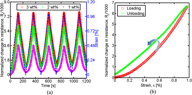
Figure 5. (a) Tensile cyclic load test results of 1, 2, and 3 wt% fabric sensors (load rate: 0.5% min−1; peak strain: 1%). (b) Hysteresis response of a 3 wt% fabric sensor during one cycle of loading/unloading.
Download figure:
Standard image High-resolution imageIn figure 5(b), Rn data of a 3 wt% fabric sensor during a complete loading/unloading cycle was extracted from figure 5(a) and plotted with respect to the applied strains. One can observe hysteresis, which could be mainly attributed to the hysteretic behavior of the fabric. Similarly, figure 6(a) plots the normalized change in resistance of representative 1, 2, and 3 wt% fabric sensors as a function of applied strains (during loading), and the results show that resistance increased in a polynomial manner. Furthermore, the rate of resistance increase was dependent on MWCNT concentrations.
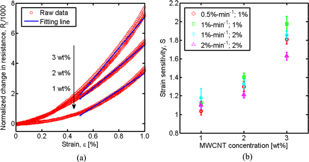
Figure 6. (a) Representative normalized change in resistance of 1, 2, and 3 wt% fabric sensors with linear regression lines fitted to the high-strain regions. (b) Summary of average strain sensitivities (and standard deviation as error bars) of fabric sensors of different MWCNT concentrations and subjected to different strain patterns.
Download figure:
Standard image High-resolution imageIn addition, this study evaluated the strain sensitivity (S) of the sensors using equation (2),

where ΔRn represents the change in Rn corresponding to applied strain (ε). Due to the polynomial electromechanical response, only resistance measurements at the high-strain regions (defined as ε ≥ 50% of peak strain) were used to estimate strain sensitivity. In addition, many human motion monitoring applications would subject fabric sensors to high levels of strain. Another reason that the low-strain response was not considered is that its reliability could be potentially compromised by possible stress relaxation of fabrics during long-term loading. In figure 6(a), linear least-square regression lines were fitted to the raw data at the high-strain regime, and it can be observed that the best-fit lines described the data adequately. According to equation (2), the slopes of fitted linear lines in figure 6(a) are equivalent to S. Therefore, the strain sensitivities of 1, 2, and 3 wt% fabric sensors when subjected to different strain patterns could be characterized, and the average values of S, as well as their standard deviations, were summarized in figure 6(b). It can be clearly seen that fabric sensors that incorporated 3 wt% MWCNT thin films exhibited higher sensitivities than their lower concentration counterparts. The results also showed that strain sensitivity was independent of the specific applied strain pattern.
3.2. Temperature sensing response
The temperature sensing characteristics of the fabric sensors were investigated by altering the ambient temperature while recording the sensors' resistance changes (section 2.4). Figure 7(a) shows a representative resistance time history of a 2 wt% fabric sensor when subjected to one heating-cooling cycle and while the actual temperature of the fabric was measured using a thermocouple. It was found that the resistance decreased when temperature was increased, and the opposite was observed during cooling. In other words, the MWCNT-latex films (i.e., the sensing elements) behaved as negative-temperature-coefficient (NTC) resistors, which is similar to many other CNT- [27, 28] or graphene-based nanocomposites reported [29–31]. It should be noted that MWCNTs are known to be metallic (i.e., electrical resistance should increase under heating) [32]; however, the macro-scale electrical property of the MWCNT-based nanocomposites could be dominated by the entire percolated MWCNT network instead of individual MWCNTs [27, 33], which explains their NTC behavior.
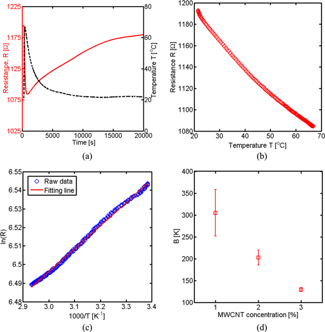
Figure 7. (a) Resistance time history of a 2 wt% fabric sensor during temperature sensing test. (b) Resistance decreased with increasing ambient temperature. (c) Linear least-squares regression line fitted to ln(R) versus T−1 data. (d) Average thermal indices (and standard deviation as error bars) of 1, 2, and 3 wt% fabric sensors.
Download figure:
Standard image High-resolution imageIt is also worth mentioning that the DMM used for measuring film resistance applied ∼1 mA DC, which would result in a very low level of dissipated electrical power (≤∼2 mW). Hence, the potential issue of resistive heating could be excluded. On the other hand, one could also observe a phase lag in the sensor's response. This could be attributed to two main reasons. The first is that the fabric could store residual heat, thereby resulting in the inner portion of the sandwich structure (i.e., where the MWCNT-based thin film was located) to cool slower than its exterior (i.e., where the thermocouple was installed). The second possible explanation is that the nanocomposite and the thermocouple had different time constants [27]. To be specific, the thin films were much larger in dimensions than the thin metallic wire-based thermocouple. Therefore, the sensing element in the fabric sensors possessed a larger time constant, resulting in slower cooling behavior.
The sensor's response during heating in figure 7(a) was extracted and plotted as a function of measured temperature, as shown in figure 7(b). One can observe a nonlinear resistance changing trend with respect to increasing temperature, which was also found in sensors fabricated with different MWCNT concentrations (not shown here). However, the sensors' response could be characterized as NTC materials using equation (3) [29, 30],
where RT represents the electrical resistance at temperature T (in K), while R0 is the resistance at the reference temperature, which was 294 K. B is a constant, depending on material properties, which can be used as a parameter for evaluating temperature sensitivity. Equation (3) can also be written as

which suggests a linear relationship between ln(RT) and T−1, considering that change in temperature (T − T0) is far smaller than T0 · T. Figure 7(c) plots ln(RT) as a function of T−1, and the data was fitted to a linear least-squares regression line. It was found that the results are well characterized by the linear best-fit line. Furthermore, based on equation (4), B for fabric sensors of different MWCNT concentrations could be calculated, whose averages and standard deviations are shown in figure 7(d). One can observe that the temperature sensitivity decreased as higher concentrations of MWCNTs were incorporated in the nanocomposites. This could be a favorable feature, since MWCNT concentration can be tuned to maximize strain or temperature sensitivity while minimizing the other, which improves selectivity.
3.3. Finger bending monitoring
To monitor finger bending movements, the fabric sensor was adhered onto a human subject's index finger, as shown in the insets of figure 8. Based on the different angles of finger bending during the tests, the entire monitoring process could be divided into three regions, namely, (i), (ii), and (iii), as marked in figure 8. Within each region, the finger bent back-and-forth multiple times. Owing to the high flexibility of the fabric sensor, it could conform to the finger and deform together, thereby generating electrical resistance changes that followed well with finger movements. Obviously, larger bending angles could generate higher changes in resistance due to greater strains being applied. Also, region (iii) in figure 8 indicates that the fabric sensor was able to detect different finger bending patterns, including holding at the same angle for a few seconds and higher frequency bending movements. On the other hand, the drift in the baseline resistance could be caused by stress relaxation of fabrics, which could be minimized if fabric sensors were pre-loaded or if the fabric sensors are later integrated with a glove instead of being directly attached to the finger.
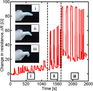
Figure 8. Change in resistance of a fabric sensor during finger bending motion tests.
Download figure:
Standard image High-resolution image3.4. Respiration monitoring
To demonstrate the fabric sensors' capability of monitoring human respiration, they were integrated with a chest band as was discussed in section 2.5. The chest band was specifically designed with snap buttons to couple with the fabric sensors, which was directly worn by the human subject. The respiration monitoring tests could be divided into two subsections based on different purposes.
In the first subsection, to validate that the fabric sensors were capable of capturing strain changes near the thorax during respiration, the human subject breathed in different patterns. In particular, the subject sometimes breathed fast and occasionally held the breath for a few seconds. Figure 9(a) shows the representative change in resistance of a 1 wt% fabric sensor due to the expansion and contraction motions of the subject's thorax during respiration. One can observe that chest expansion introduced increases in resistance (i.e., applied tension to the sensor), while contraction enabled resistance to restore back to its original level (i.e., released tension). The fabric sensor exhibited stable, reversible, and repeatable response with high signal-to-noise ratio. Besides, figure 9(b) illustrates that sharp peak-like (i) and step-like (ii) resistance changes could be correlated to fast breathing and breath-holding, respectively. Thus, by integrating the fabric sensors with a chest band, respiration could be monitored in real-time.
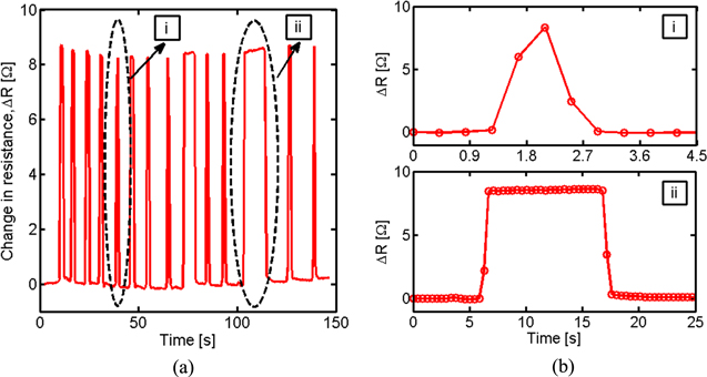
Figure 9. (a) Change in resistance of a fabric sensor during respiration monitoring test. (b) Regular breathing shows sharp peak in ΔR plot (i), whereas breath-holding leads to step-like response (ii).
Download figure:
Standard image High-resolution imageFurthermore, this study also used the fabric sensor measurements for estimating respiration rate (as a significant vital signal). To accomplish this, instead of tediously counting the number of resistance change peaks (i.e., number of breaths taken), the fast Fourier transform (FFT) was used to convert time-domain data to the frequency-domain. Therefore, for this case, the human subject held still and breathed deeply at a slow but regular rate. The data acquisition system recorded data at three times the sampling rate (66 Hz) as compared to previous tests but would unfortunately introduce higher levels of baseline noise to the raw data. To compensate for this, the collected data was first processed using a moving-average approach [34]. Figure 10(a) shows the moving-average, down-sampled, resistance time history results, in which the moving-average was computed using every 51 sets of data. It is clear that the sensor was still able to quantify resistance changes due to respiration. In addition, one can also observe from figure 10(a) certain amounts of baseline resistance drift. This could be a coupled result of ambient temperature changes and slight body movements, among others. Therefore, the goal of using FFT was to extract respiration rate in light of noisy and resistance drifts due to ambient effects. In this study, FFT was conducted using a 60 s moving-window with a time step of 2 s. An example time window, as well as the sensor's response within the time window, is presented in the inset of figure 10(a).
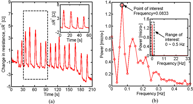
Figure 10. (a) Change in resistance of a fabric sensor acquired during respiration monitoring tests. Inset shows sensor response within a narrower time window. (b) Representative power spectrum of respiration monitoring resistance time history data. Inset shows power spectrum peak in which the frequency corresponds to respiration rate.
Download figure:
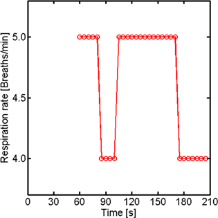
Standard image High-resolution imageThe inset of figure 10(b) demonstrates the corresponding power spectrum (i.e., FFT result) of the same time window shown in the inset of figure 10(a). The dominant peak of the power spectrum would occur in the frequency range from 0 to 0.5 Hz, which was then considered as the range of interest. Figure 10(b) zooms in the power spectrum in the 0–0.5 Hz frequency range. The frequency corresponding to the peak of the power spectrum peak in figure 10(b) corresponds to the human subject's respiration rate. Since this moving-window FFT analysis was performed in real-time (i.e., using a time window with a step size of 2 s), the extracted respiration rate for each window could be calculated and plotted as a function of time and in real-time, as shown in figure 11. The results shown in figure 11 suggest that these fabric sensors could be potentially used for monitoring respiration. It should be note that, since the human subject breathed deeply during this test, the respiration rate was relatively slow at 4–5 breaths min−1.
Figure 11. Plot of computed respiration rate (updated every 2 s) in real-time.
Download figure:
Standard image High-resolution image
4. Conclusions
This study aimed to develop a multifunctional, wearable, fabric sensor for monitoring small human motions, as well as vitals such as body temperature and respiration rate. The fabric sensors leveraged the mechanical and electrical properties of MWCNT-based nanocomposites. Here, the nanocomposite thin films were spray-coated to form freestanding films and then integrated with fabrics by ironing, forming an integrated, reliable, and sandwiched structure. Then, their electromechanical and temperature sensing properties were characterized. The results showed that they exhibited stable and repeatable strain sensing properties, and strain sensitivity increased as higher concentrations of MWCNTs were used. For temperature sensing, it was found that they were characterized by negative temperature coefficient behavior and became less sensitive as MWCNT concentrations increased. Thereafter, this work continued to investigate the fabric sensors' suitability for practical human monitoring applications. First, the sensors were used to detect finger bending movements as a proof-of-concept demonstration for human motion monitoring. It was found that they could capture different bending motions and exhibited relatively stable response. Second, the fabric sensors were integrated with a chest band for monitoring respiration or breathing. The resistance change of the fabric sensors was well-correlated with the expansion and contraction movements of the subject's thorax. Furthermore, respiration rate was successfully extracted using a moving-window FFT analysis, and the results can be visualized in real-time. The results obtained in this study suggest that these MWCNT-based fabric sensors could potentially be used for applications such as multifunctional wearable sensors or be integrated as part of 'smart garments'. Future work will involve testing conducted in more realistic and challenging environments so as to demonstrate their field applicability.
Acknowledgments
This research was partially supported by the US National Science Foundation (NSF) grant numbers CMMI CAREER-1253564. The authors also thank the Jacobs School of Engineering, University of California-San Diego, for providing additional support for this work. Furthermore, the authors gratefully acknowledge the collaboration of Professor Helen S Koo at the University of California-Davis (USA).