

Abstract
Actuator-type applications of high temperature shape memory alloys (HTSMAs) require better understanding of the crack growth behavior at high temperatures as there are few studies on how cracks propagate and cause fracture with phase transformation via cooling and heating under constant load. In this study, hot-extruded and subsequently annealed Ni50Ti30Hf20 (at.%) HTSMA dog-bone shaped tensile test samples with pre-notches were cooled and heated under uniaxially applied constant load magnitude till fracture. Therefore, the crack growth behavior and effect of annealing heat treatment on the crack growth rate of Ni50Ti30Hf20 (at.%) HTSMA during actuation fatigue were particularly determined. Additionally, fatigue tests were conducted twice on the pre-notched samples to investigate the repeatability of the data obtained from the experiments. It was shown that slower crack growth was observed in the pre-notched annealed samples than in the hot extruded samples because of the possible stress-relieving effect of annealing after the hot extrusion process. Several minor side crack formations and the propagation of these side cracks together with the crack growth behavior of the major crack were realized in the annealed samples. In contrast, the major crack growth rate was found to be higher than that of the growth rate of the minor side cracks. Additionally, the annealing process led to obtain consistent crack growth rate values and actuation behavior in the cooling-heating cycles.
Export citation and abstract BibTeX RIS
1. Introduction
Shape memory alloys (SMAs) are unique materials with their ability to recover their shape change via thermal and/or mechanical stimulation from low temperature martensite phase to high temperature parent phase austenite. The shape change recovery under load can be achieved when the alloy is heated above a certain temperature. They produce work against the applied load through this shape change mechanism [1, 2]. Large recoverable strain magnitudes under high applied forces provide very high work output per volume. Also, they can perform functions of several devices by simplifying machine design with fewer parts which leads to reduce costs for maintenance of the machine components [3].
Due to the aforementioned reasons, SMAs are used as actuators and constraining components in several industries such as in biomedical, civil, automotive and aerospace [4–9]. While the superelastic properties of SMAs are utilized in biomedical and structural applications, they are preferred as system actuators in aerospace industry due to their shape memory properties. For instance, the offshore platforms, bridges and buildings are exposed to earthquakes, therefore, it is extremely important to decrease the residual displacements and/or stresses on these structures by using SMAs via controlling their responses to seismic loadings [10]. In general, SMAs are used as brace and/or washer springs kind of components in construction industry due to their energy dissipation capability with loading and unloading [6, 7, 10]. On the other hand, SMAs are mostly used as actuation components in aerospace industry in the forms of torque tubes or beam plates to replace the heavy weight pneumatic or DC motors. For instance, NiTi SMAs have been already utilized to active control of the chevron geometry for noise reduction in planes [9, 11]. NiTi SMAs are most commonly used and studied alloys due to their good dimensional stability and shape memory properties, ductility, workability and availability in different geometric forms [11, 12]. However, their transformation temperatures are limited to 100 °C (<100 °C), which restrict them from being used at elevated temperatures. Relatively lower transformation temperatures would result in an unintentional actuation while utilizing NiTi alloys in energy conversion systems and compact actuators and therefore there is a high demand for developing SMAs operating above 100 °C without losing their strength and actuation abilities. To increase the transformation temperatures, Au, Pd, Pt, Zr, Hf are used as ternary additional alloying elements in NiTi binary systems. Hf and Zr are found to be the most promising additional elements due to their cost advantage, but Hf is the most preferred one because of its effectiveness in increasing the transformation temperatures [11–14].
SMAs with transformation temperatures above 100 °C are referred to as high temperature shape memory alloys (HTSMAs). There are many studies on Ni-rich NiTiHf HTSMAs which might include Ni-rich precipitates. These precipitates that are formed by applying aging heat treatments lead to a decrease in the Ni content of the matrix and an increase of transformation temperatures. Moreover, equiatomic NiTiHf alloys having 20 at.% or higher Hf content show transformation temperatures above 200 °C, thus, equiatomic NiTiHf alloys would be also good candidates for high temperature applications [15–19].
In typical engineering materials, structural fatigue that occurs due to cyclic loading results in the accumulation of dislocations. These dislocations cause crack formation and crack initiation is followed by crack propagation then the fatigue failure is observed by fracture. However, in SMAs, different type of fatigue behavior should be investigated since these materials go under phase transformations by heating-cooling cycles under constant load instead of cyclic load change. Fatigue in SMAs leading to degradation in functional properties is called as functional fatigue [19, 20].
Functional fatigue could be subdivided into two categories by considering the triggering of phase transformation. Functional fatigue that is caused by stress induced phase transformation via cyclically loading at constant temperature is called as pseudoelastic fatigue (isothermal fatigue) and functional fatigue that is caused by thermally-induced phase transformation via conducting heating and cooling cycles under constant load is called as actuation fatigue [20]. Many studies have been done regarding the pseudoelastic fatigue especially on NiTi alloys in contrast to actuation fatigue [21–26].
There exist a limited number of experimental investigations on actuation fatigue of SMAs. Effect of applied load level [27] and upper cycle temperature [15] together with the effect of corrosion environment [28, 29] to the actuation fatigue properties and the microstructural damage evolution during actuation fatigue were examined and reported in the literature [20]. However, there are a couple of studies on the crack growth response of especially NiTiHf HTSMAs to the best of authors' knowledge. There is a need to understand the fatigue crack growth properties since SMA actuators are designed to work under cyclic loadings. However, crack growth during actuation cycles is not easily explicable due to the fact that the fatigue crack growth approaches still based on developed theories for structural metal alloys which do not show phase transformation [30].
There are two approaches to investigate the fatigue, which are total-life and damage tolerant approaches. Literature has relatively more studies on total life approach instead of damage tolerant approach, since SMAs used in the commercial market are in small sizes such as NiTi alloys which are preferred in the production of implants. Therefore, in these biomedical applications, preventing crack nucleation is more important than controlling the crack growth [31], because when the crack nucleates in small sized components, failure occurs after a short period of time. However, damage tolerant approach accounts the initial crack already existing in a structure and the resistance to crack growth with cyclic loading. It is more proper to use this approach when the structure is in a stress-controlled environment with an initial flaw. In other words, damage tolerant approach is more suitable, when the part is large enough to maintain the stable crack growth and the functionality of the part during its service time in the presence of defects. Thus, this approach is more applicable in investigating the crack growth behavior of SMAs which are used in actuator applications since the actuators generally work under constant loads or stresses. However, application of damage tolerant approach in SMAs is different and more challenging than that of conventional structural metals, since reversible phase transformation, martensite reorientation and thermomechanical coupling are the main considerations in investigating the crack growth in SMAs [31, 32].
There are few studies examining the crack growth experimentally during actuation fatigue in SMAs. Iliopoulos et al [33] had experiments on the double notched Ni60Ti40 (at.%) specimens during actuation under load and observed fracture due to an unstable crack propagation during cooling. Jape et al [34] conducted experiments on pre-notched compact tension Ni49.5Ti50.5 (at.%) specimens under actuation loading and they found that the crack was advanced during cooling in actuation cycling. However, there are not many works investigating the crack growth behavior during actuation fatigue in NiTiHf HTSMAs.
In this study, crack growth behavior during actuation cycling under constant load of pre-notched Ni50Ti30Hf20 (at.%) samples was investigated by measuring the crack length changes via using optical micrographs. Strain-temperature data which were obtained during actuation cycles were also collected. Additionally, the effect of annealing heat treatment on crack growth behavior of Ni50Ti30Hf20 (at.%) HTSMA during actuation fatigue was particularly determined as well.
2. Experimental procedure
Ni50Ti30Hf20 (at.%) alloy was produced by using high purity elemental materials of Ni, Ti, and Hf via vacuum induction melting under high purity argon atmosphere. Then, the as-cast bulk material billet was sealed in a mild steel can to minimize the oxidation during hot extrusion and hot extruded at 900 °C with an area reduction of 4:1 to homogenize the cast structure and chemistry. Small dog-bone shaped single edge notch test samples were cut from hot extruded material with a gage length of 16.6 mm, width of 2.25 mm, thickness of 1 mm and a notch was opened with a width of 0.40 mm and 0.3 mm depth (perpendicular to the loading direction—lateral axis (X)) by using wire electrical discharge machine (Wire EDM). Dimensions of the sample and the notch were given in figure 1.

Figure 1. (a) Schematics of pre-notched Ni50Ti30Hf20 (at.%) HTSMA sample (b) Wire EDM cut sample.
Download figure:
Standard image High-resolution imageThe extruded samples were first separated into two parts for actuation fatigue experiments. One part was fatigue tested in hot extruded condition and the other part was annealed at 550 °C for 3 h before the fatigue experiments. Hot extruded pre-notched samples and hot extruded, annealed and pre-notched samples will be called as 'HE-PN' and HE-PN-AN, respectively throughout the text. Actuation fatigue experiments were repeated for two times for each type of samples to ensure repeatability of the data. Sample 1 and Sample 2 were 'HE-PN' samples, and Sample 3 and Sample 4 were 'HE-PN-AN' samples. Surfaces of the samples were grinded before the experiments with the papers having 600-800-1000 and 1200 grit sizes in order to reduce Wire EDM based micro cracks and residual layers.
The transformation temperatures of both Ni50Ti30Hf20 (at.%) HE-PN and HE-PN-AN samples were previously determined and reported as Af = 330 °C, As = 286 °C, Ms = 282 °C, Mf = 236 °C for the extruded sample and Af = 328 °C, As = 281 °C, Ms = 282 °C, Mf = 229 °C for the annealed sample [19].
Actuation fatigue experiments were performed on pre-notched samples by running cooling-heating cycles under constant load to experience martensite-austenite phase transformation using custom made test set-up by hanging dead weights to the bottom grip. The constant load magnitudes varied between 456 N and 468 N depending on the cross section of the samples since 200 MPa stress magnitude was aimed to apply to the samples at the beginning of the experiments. It is important to note that there were very small variations in the dimensions of the samples' gage sections. The applied load magnitudes to the samples are shown in table 1.
Table 1. The load magnitudes that were applied to the samples in actuation fatigue experiments.
| Sample 1 | Sample 2 | Sample 3 | Sample 4 | |
|---|---|---|---|---|
| Load magnitude (N) | 468 | 466 | 457 | 463 |
The schematic representation of the test set-up is shown in figure 2(a) and the number of samples, which were used in this study, is given in figure 2(b). The cooling-heating rate was kept constant as 15 °C s−1. Heating was conducted by Joule Heating via current passing through the samples and cooling was generated by conventional open-air cooling. A linear potentiometric displacement sensor that was attached to the bottom grip was used to measure displacement during the heating cooling cycles. Optris Ct Laser LTF-CF1 infrared thermometer was placed to measure the temperature by focusing the mid-section of the sample's gage length and close to the notch. Thermal emissivity of the test sample should be known, since temperature values measured by the infrared thermometer are translated at the logger according to thermal emissivity value. Thermal emissivity value of NiTiHf material is not known, therefore, all the samples were sprayed with high temperature black paint and the emissivity value was taken as 0.95. Hereby, the temperatures of the samples throughout the actuation fatigue experiments were able to be measured accurately. The samples were heated to 440 °C, which was set as the upper cycle temperature and cooled down to 150 °C, which was set as the lower cycle temperature. Temperature and displacement data were recorded by National Instruments USB-6003 data logger. The upper and lower cycle temperatures and cooling-heating rate parameters were entered to Labview Software which controls the fatigue experiments.
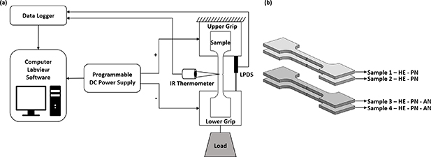
Figure 2. (a) Schematics of the test set-up [35]. (b) Representation of dog-bone test samples (two pre-notched hot extruded samples and two pre-notched samples which were annealed after extrusion).
Download figure:
Standard image High-resolution imageThe crack length measurements were done using optical microscope at different magnification levels for every after 200 cooling-heating actuation cycles. Stress intensity factor (SIF) which is related with the rate of crack growth and showing the stress distribution intensity at the crack tip was calculated for all samples by using notch dimensions from crack length measurements. K is proportional to applied stress ( , geometric factor
  and square root of flaw size as shown in equation (1) [31, 36].
  is the remote loading stress and it was taken as the constant nominal stress value applied during actuation fatigue experiments. There are several equations for calculating SIFs considering different sample and crack geometries and loading conditions. In this study, the stress intensity and geometric factor values were calculated regarding the empirical relations stated in Tada–Paris–Irwin's Stress Analysis of Cracks which was defined by Tada in 1973 [36, 37]. The geometric factor function, which is represented as
  , was chosen for single edge notched samples where a is the crack length and b is the width of sample in equation (2). It is stated that this equation provides accuracy better than 1% when a/b is smaller than 0.2, and better than 0.5% when a/b is equal and/or higher than 0.2 in determining the SIF [36]. Since a/b ratio which was calculated by measuring the crack length after each 200 actuation cycles is mostly less than or close to 0.2, equation (2) was used to determine the geometric factor values showing better accuracy:
3. Results and discussions
3.1. Actuation fatigue experiment results
Actuation fatigue experiments were conducted on pre-notched HE-PN and HE-PN-AN Ni50Ti30Hf20 (at.%) samples by applying thermo-mechanical cycling with 15 °C s−1 heating-cooling rate under constant load. It is important to emphasize that the load magnitudes that were shown in table 1 were calculated to apply a stress magnitude of 200 MPa to the samples and it has been already known that the applied stress increases as the sample undergoes plastic deformation and as the necking occurs with the number of cycles, however, it is impossible to regulate the applied load during the heating-cooling cycles to keep the stress constant with the dead weights shown in figure 2(a). Strain vs temperature curves that were obtained from these experiments for HE-PN and HE-PN-AN samples were demonstrated in figures 3(a) and (b), respectively. The actuation strain ( act) and accumulated irrecoverable strain (austenite) with respect to number of cycles until failure were drawn via following the procedure which was previously defined in the literature [15] and shown in figures 4 and 5.

Figure 3. Strain vs temperature curves which were obtained from the actuation fatigue experiments of (a) HE-PN and (b) HE-PN-AN samples.
Download figure:
Standard image High-resolution image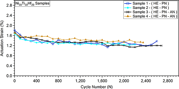
Figure 4. Actuation strain values which were drawn from the actuation fatigue experiments of HE-PN and HE-PN-AN samples.
Download figure:
Standard image High-resolution image
Figure 5. Accumulated irrecoverable strain values drawn from the actuation fatigue experiments of HE-PN and HE-PN-AN samples.
Download figure:
Standard image High-resolution imageActuation strain was described as the difference of strain values at martensite state and austenite states. Figure 4 represents the actuation strain values for all samples. It is worth to recall that the experiments were repeated twice on HE-PN and HE-PN-AN samples. Actuation strain values with the number of cycles decreased as expected over cycles due to retained martensite and the plastic strain accumulation with the actuation cycles. It is also worth to note that the work output, which can be calculated by multiplying the applied stress with actuation strain, also decreased with the decrease in the actuation strain. However, work output which was determined for all samples was approximately the same at all cycles.
In figure 5, accumulated irrecoverable strain values were plotted with the number of cycles. Accumulated irrecoverable strain values continued to increase and did not saturate for all samples which might be due to the pre-notch and the growth of the cracks from the notches. While all samples showed the similar increasing trend at the beginning, accumulated irrecoverable strain values of HE-PN samples were noticeably different than each other. Additionally, a jump in the accumulated irrecoverable strain values of Sample 1 was observed at the end of the fatigue cycles which can be attributed to the black paint peeling of the surface of the samples. At the end of the fatigue experiments, the excessive crack formations on the surface of the samples caused the black paint to peel off and therefore the temperature measurement became difficult. As the temperature cannot be measured accurately, the samples might be heated to temperatures higher than the upper cycle temperature (440 °C) which led to observe a jump in the accumulated irrecoverable strain value due to excessive plastic deformation and crack growth at high temperatures. On the other hand, the annealed samples showed similar increasing accumulated irrecoverable strain trend and values until failure. The similarity in the irrecoverable strain values of HE-PN-AN samples can be attributed to the stress relief and homogenized extruded microstructure via annealing as explained in the previous study [19].
3.2. Major crack length change
The evolution of the crack size was investigated by measuring the length of the major crack which was started to propagate from the pre-notch with the number of cooling-heating cycles of actuation fatigue experiments that were conducted on the HE-PN and HE-PN-AN samples. Crack length was measured after every 200 actuation cycles. The crack length evolution of HE-PN and HE-PN-AN samples with the number of cycles was presented in figure 6 and in figure 7, respectively. Initial crack length of the samples in figures was taken as the depth of the pre-notches which was previously presented with the letter 'a' and was around 0.3 mm (300 µm). Best fit lines that passed through the data points were drawn for all samples and the slopes of these lines were calculated. The slope values that were presented with the letter 'm' showed the crack growth rate (µm/cycle) for all samples, but, it is worth to mention that the crack growth rate vs stress intensity range (ΔK) cannot be drawn in this study since the crack growth occurs due to thermally induced phase transformation via thermal cycling under constant load instead of applying alternating stress magnitudes. Experiments were repeated for two times on each HE-PN (Sample 1 and Sample 2) and HE-PN-AN (Sample 3 and Sample 4) samples. While the results of Sample 1 and Sample 2 were presented in figures 6 and 7 showed the crack length evolution of Sample 3 and Sample 4 which were annealed after opening pre-notch by Wire EDM.

Figure 6. Crack length evolution with the number of cycles of HE-PN samples.
Download figure:
Standard image High-resolution image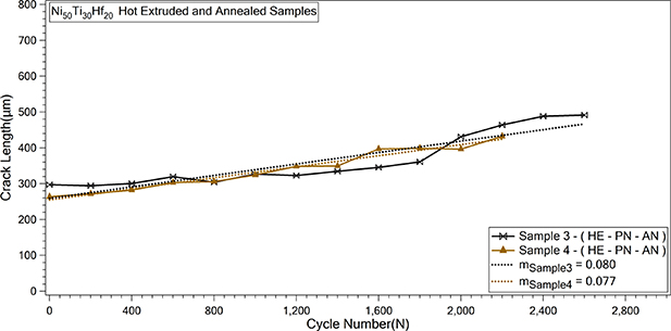
Figure 7. Crack length evolution with the number of cycles of HE-PN-AN samples.
Download figure:
Standard image High-resolution imageThe crack growth rates of Sample 1 and Sample 2 which were represented with the letter 'm' were calculated as 0.099 and 0.147, respectively. As it can be seen in figure 6, the crack lengths measured after 200 cycles in two hot extruded pre-notched samples and also the crack growth rates were found to be different from each other. However, the noticeable increase in leading major crack length of each sample was seen after 400 actuation cycles.
Annealed samples (Sample 3 and Sample 4) showed similar crack lengths after each 200 cycles and crack growth rates as it is shown in figure 7. Crack length values of HE-PN-AN samples were similar at the beginning and did not increase significantly. Unlike hot extruded pre-notched samples, crack growth in annealed samples was slower initially and then the increase in crack size after 1400 cycles leaded to fracture at the end.
Small decreases in crack lengths (about 15 µm) at some actuation cycles may be due to the contraction of the pre-notch in lateral direction (X axis) and elongation of the pre-notch in the load application direction (Y axis) as a consequence of the sample's elongation after many actuation cycles. Please note that the lateral and the load application directions were previously defined in figure 1.
Crack growth rate values 'm' of HE-PN-AN samples were determined as 0.080 and 0.077 and 'm' values of all samples were given in table 2 for comparison. Slope values of HE-PN-AN samples were lower than that of HE-PN samples. The reason might be due to annealing since the induced stress by hot extrusion was relieved and the microstructural uniformity was achieved by annealing process as was explained previously in the study of Akin et al [19].
Table 2. Crack growth rate values ('m') showing crack length change trend of hot extruded and annealed samples.
| 'm' values | Sample 1 | Sample 2 | Sample 3 | Sample 4 |
|---|---|---|---|---|
| Crack length change (µm/cycle) | 0.099 | 0.147 | 0.080 | 0.077 |
3.3. Optical micrograph investigation of crack growth
In order to take a closer look at the formation and propagation behavior of cracks with the number of actuation fatigue cycles, optical micrographs after every 200 cycles were taken. Figure 8 represents the location where the crack images of HE-PN and HE-PN-AN samples were taken before the fatigue experiments and just before the fracture.

Figure 8. The location where the crack images were taken and the crack images of HE-PN and HE-PN-AN samples before the actuation fatigue experiments and just before the fracture.
Download figure:
Standard image High-resolution imageFor sample 1, measured pre-notch length in lateral axis and load axis before starting the test were 280 µm and 422 µm. It has been determined that a difference in the dimensions of the cracks can occur due to the precision of EDM cutting method.
In figure 9, optical micrographs of propagation of the major cracks and formation of the side cracks with the number of actuation cycles in the HE-PN and HE-PN-AN samples were shown. The images were taken after each 200 actuation cycles and presented for 1200th, 1400th, 1600th, 1800th and 2000th cycles. As seen in figure 9, several minor side cracks were formed and propagated together with the growth of the major crack during the actuation cycles of annealed samples (HE-PN-AN). In fact, the length of most of the side cracks was the same as the major crack after a while. On the other hand, there were not many minor side cracks in the HE-PN samples as were observed in HE-PN-AN samples since the growth rate of the major crack was always higher. It was easier to distinguish major cracks, which grew from the pre-notch with the actuation cycles in the optical micrographs of HE-PN samples in figure 9. The difference in the crack formation and growth behavior between HE-PN and HE-PN-AN samples can be attributed to the annealing process which promotes stress relief caused by hot extrusion in addition to dislocation rearrangement. In an actuation cycle, almost similar magnitude of actuation (act) and accumulated irrecoverable strain (austenite) values were observed for all samples under the similar applied load magnitude, as it was shown in figures 4 and 5. Therefore, almost same magnitude of work output was achieved from all samples. As it has been already known from fracture mechanics that the work done which can be converted to energy should be spent for the crack formation and propagation. The energy which can be converted from work done via applying the same stress/load should be spent to phase transformation and the crack formations and propagations in pre-notched samples. Since the actuation strain and hence the work output values due to phase transformation were found to be almost the same for all samples, the energy that was spent for crack formations and propagations would be the same for all samples as well. While this energy was spent in the propagation of the pre-notch in the HE-PN samples, the same magnitude of energy was spent not only in the propagation of the pre-notch but also formation of the minor side cracks in the HE-PN-AN samples. This might be due to the fact that, the annealed samples were relatively free from stress which was induced during hot extrusion and thus it was relatively easy to create new surfaces via spending less energy.

Figure 9. Optical micrographs of pre-notch, major crack and side cracks of HE-PN and HE-PN-AN samples after 1200th, 1400th, 1600th, 1800th and 2000th cycles.
Download figure:
Standard image High-resolution imageIn addition, although pre-notches were opened at the edges of the samples by WEDM and this method is accepted to be the most appropriate method with the given notch dimensions, residual stresses could occur around the pre-notch. However, annealing could relieve these residual stresses and hence the growth rate of the pre-notch in HE-PN-AN samples was observed to be less than that of HE-PN samples.
Figure 10 showed the optical micrograph of pre-notch and cracks around the pre-notch after 1800th and 2000th cycles for HE-PN-AN sample (Sample 3). The sudden increase in total crack length of HE-PN-AN Sample 3 from 1800th to 2000th actuation cycles was due to simultaneously joining minor cracks after 200 cycles.
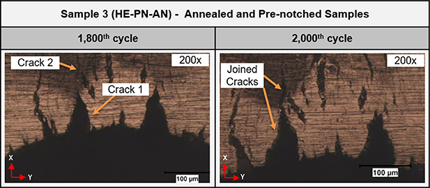
Figure 10. Optical micrographs of pre-notch, major crack and side cracks of HE-PN-AN sample after 1800th and 2000th actuation cycles.
Download figure:
Standard image High-resolution image3.4. SIF
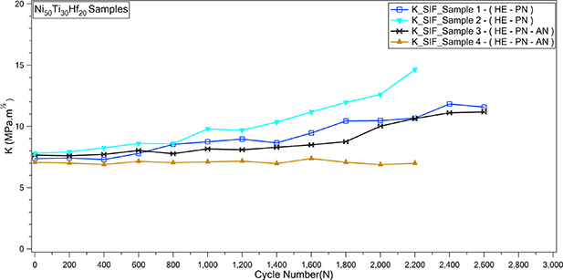
SIF values were calculated via using the equation of Tada et al [36], which was shown in the previous section by using geometric factor and crack length dimensions. As shown in figure 11, the increase in SIF values after actuation cycles were mitigated by annealing processes because of the rearranged dislocations and relieved stresses induced by hot extrusion process. SIF values were almost stayed constant for the first 1800th cycles of HE-PN-AN samples.
Figure 11. Calculated SIF values of HE-PN and HE-PN-AN samples.
Download figure:
Standard image High-resolution image
4. Conclusion
In this study, the crack growth behavior of hot extruded and hot extruded and annealed Ni50Ti30Hf20 (at.%) alloy was investigated during the actuation fatigue cycles of single pre-notched samples. The results that were gathered from this study are summarized below:
- Crack growth of annealed samples (HE-PN-AN) was slower than that of hot extruded (HE-PN) samples due to annealing since the induced stress by hot extrusion was relieved.
- Energy was spent in the propagation of the pre-notch in the HE-PN samples during actuation fatigue, however the same magnitude of energy was spent not only in the propagation of the pre-notch but also in the formation of the minor side cracks in the HE-PN-AN samples. Since the annealed samples were relatively free from induced stress during hot extrusion, it was relatively easy to create new surfaces around the pre-notch via spending less energy during actuation fatigue. Thus, although same amount of work magnitude was done on all samples, annealed samples showed several minor side cracks formations and these side cracks were propagated with the same crack growth rate of the major crack during the actuation cycles.
- Crack length values of hot extruded pre-notched samples and crack growth rates were relatively different from each other, while annealed samples showed similar crack growth trends.
- Knowing the crack growth behavior under actuation fatigue may contribute positively to the usage of HTSMAs in actuation applications since there is huge pressure in clarifying the fatigue behaviors of these alloys for high temperature applications by considering their reliability problem. It can be stated that annealing heat treatment could lead to observe more stable crack growth behavior together with constant SIF and lower crack growth rates during actuation fatigue of Ni50Ti30Hf20 (at.%) HTSMAs.
Acknowledgments
This study was supported by the Turkish Aviation Industry under Grant No. DKTM/2015/10 and is a part of first author's PhD Thesis.
Data availability statement
The data that support the findings of this study are available upon reasonable request from the authors.
CRediT authorship contribution statement
Meric Ekiciler: conceptualization, methodology, experimentation, data curation, writing—original draft, editing. Benat Kockar: writing—review & editing, validation, supervision, funding acquisition, resources, project administration.
Conflict of interest
The authors declare that they have no known competing financial interests or personal relationships that could have appeared to influence the work reported in this paper.