

Abstract
This paper presents a new trapped-field magnet made of second-generation high-temperature superconducting (2G HTS) rings. This so-called ring-shape 2G HTS magnet has the potential to provide much stronger magnetic fields relative to existing permanent magnets. Compared to existing 2G HTS trapped- field magnets, e.g. 2G HTS bulks and stacks, this new ring-shape 2G HTS magnet is more flexible in size and can be made into magnets with large dimensions for industrial applications. Effective magnetization is the key to being able to use trapped-field magnets. Therefore, this paper focuses on the magnetization mechanism of this new magnet using both experimental and numerical methods. Unique features have been identified and quantified for this new type of HTS magnet in the field cooling and zero field cooling process. The magnetization mechanism can be understood by the interaction between shielding currents and the penetration of external magnetic fields. An accumulation in the trapped field was observed by using multiple pulse field cooling. Three types of demagnetization were studied to measure the trapped-field decay for practical applications. Our results show that this new ring-shape HTS magnet is very promising in the trapping of a high magnetic field. As a super-permanent magnet, it will have a significant impact on large-scale industrial applications, e.g. the development of HTS machines with a very high power density and HTS magnetic resonance imaging devices.
Export citation and abstract BibTeX RIS
1. Introduction
Second-generation high-temperature superconducting (2G HTS) trapped-field magnets have significant potential for a variety of engineering applications in the provision of a strong magnetic field and in replacing conventional permanent magnets, e.g. samarium-cobalt and neodymium-iron-boron. Bulk, single grain RE-Ba-Cu-O ((RE)BCO, where RE is a rare-earth element) superconductors have been a research focus for more than 20 years. Using the top seeded melt growth (TSMG) process and reinforcement technique, the record for a trapped field has exceeded 17 T for a single grain YBCO bulk [1, 2]. A multiple seeding technique has been used to increase the size of YBCO bulks [3–5], and 2G HTS bulks have been demonstrated as trapped-field magnets for electrical machines [6, 7], as well as self-stabilizing bearings for energy storage flywheels and magnetic separation devices [8, 9]. The magnetization of 2G HTS bulks has been studied extensively, partly because it is a key challenge. Pulsed field magnetization (PFM) has been identified as an effective and practical way of magnetizing 2G HTS bulks [10–13]. Due to the heat generated in the stack, the trapped field and flux acquired by PFM is usually less than that acquired by field cooling or zero field cooling methods, especially at lower temperatures [14, 15]. Therefore, effort has been devoted to optimizing the PFM process to improve the trapped field with PFM. A recent study has shown that a higher trapped field can be achieved using flux jump-assisted PFM or slit coils [16, 17]. Thermally coupled numerical models have been developed to simulate the trapped field during the PFM process and study the influence of grain boundaries [18, 19].
More recently, with the maturing of YBCO-coated conductor technology, stacks of YBCO tapes have been proposed as a new type of trapped field magnet with a maximum reported trapped field of 7 T [20, 21]. Compared to melt-processed bulks, it is relatively easier to make a stack of YBCO tapes and control their quality. PFM and flux pumping for a stack of YBCO tapes has been demonstrated [22]. Modelling of the stack of YBCO tapes has been reported, which takes into account the effect of stabilizers [23, 24]. Both types of HTS trapped field magnets have a size limitation. The diameter of single grain 2G HTS bulks is usually less than 40 mm, while the maximum width of a stack of YBCO tapes is the width of a commercial YBCO-coated conductor (46 mm).
This paper reports on a new type of 2G HTS trapped field magnet, which is called a ring-shape 2G HTS magnet. As shown in figure 1, by splitting 2G HTS coated conductors, shaping them into a ring and stacking them into a magnet, a ring-shape 2G HTS magnet can be easily constructed. The main advantage of the new magnet is that it can be of a feasible size. By choosing different lengths of the split, we can adjust the diameter of the magnet. This ring-shape 2G HTS was inspired by the wind-and-flip method, which was used to construct joint-less 2G HTS coils for NMR/MRI applications [25–31] and fault current limiters [32, 33]. Instead of using one piece of YBCO conductor to wind into coils and applying a DC current, our ring-shape trapped-field magnets use stacks of ring-shape YBCO conductors [34]. The trapped field comes from induced persistent current loops using conventional magnetization methods, e.g. field cooling, zero field cooling and pulsed magnetization.
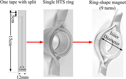
Figure 1. The construction of the ring-shape YBCO magnets.
Download figure:
Standard image High-resolution imageDue to the difference in geometry, the magnetization of the ring-shape magnet can be understood by neither the Bean model nor existing knowledge obtained from the study on 2G HTS bulks and stacks of tapes. Therefore, this paper presents, for the first time, a thorough study of the ring-shape HTS magnet, with a particular focus on the magnetization and demagnetization mechanism. We employed both the experimental method and numerical modelling to unveil the electromagnetic performance of the new magnet. The paper is organized as follows: section two presents the magnetic field distribution of the magnet and our experimental setup; section three focuses on three types of magnetization for the ring-shape magnets: field cooling, zero field cooling and multiple pulse field cooling; section four focuses on the demagnetization process.
2. Experimental setup and modelling
2.1. Magnet construction and magnetic field mapping
Figure 1 illustrates the construction process of our sample ring-shape 2G HTS magnet. First, 15 cm long YBCO tapes (12 mm wide, self-field critical current 317 A in 77 K, manufactured by Superpower) were split by mechanical cutting. The split opening in the centre of the tape is 120 mm long and 1 mm wide, with 15 mm spare tape at each end. Nine YBCO rings are stacked together to form the magnet and a round G10 former was inserted into the ring opening (diameter 50 mm) to maintain the ring shape.
Figure 2 shows the theoretical magnetic field distribution of the ring-shape YBCO magnet with a maximum trapped field of 77 K obtained by a 3D real size model. The trapped field in the centre plane (z = 0 mm) is shown in figure 2(a). The central fully trapped field is 25 mT, which is defined as Bp (full penetration field density) in the following discussions. Figure 2(b) plots the magnetic field density Bz 4 mm above the magnet (z = 10 mm). Due to the asymmetric geometry in the axial direction, the ring-shape magnet has the angle deflection of a trapped magnetic field. This angle deflection leads to asymmetric magnetic field distributions. In this case, the upper bar generates a magnetic field which is about 10 mT higher than the central field. A strategy to reduce the field asymmetry has been proposed using a double split structure [35]. In this case, we focus on the single split structure, as shown in figure 1.
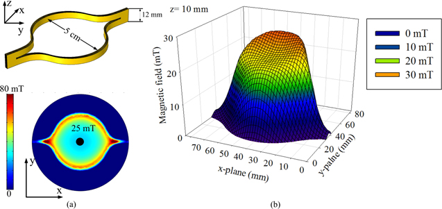
Figure 2. The magnetic field distribution (Bz) of the sample magnet when it is fully penetrated: (a) centre plane z = 0 mm; (b) z = 10 mm. The sample coil has an inner diameter of 5 cm, the trapped field is in the z directions.
Download figure:
Standard image High-resolution image2.2. Experiment
Figure 3 shows our testing rig, which consists of an iron-core-based DC magnet to provide the external magnetic field, a sample holder to support the ring-shape magnet, a calibrated low-temperature Hall sensor and an NI data acquisition system. The DC magnet can provide a uniform magnetic field in the central air gap; the amplitude of the magnetic field can be manually set to a value between 0 and 0.4 T. The magnet can be programmed to achieve different kinds of waveforms with a minimum time step of 1 s. The HHP-NP Hall sensor (error < 0.2% below 1 T) is placed in the centre of the magnet. To magnetize the ring, we use three methods: field cooling (FC), zero field cooling (ZFC) and multiple pulse field cooling (MPC). We control the DC power supply of the copper magnet to achieve these three magnetization methods. Figure 4 illustrates the difference between FC, ZFC and MPC. For FC, we apply an external magnetic field, gradually cool down the ring-shape magnet, and then remove the external field. For ZFC, we cool down the magnet first, and apply a positive pulse field waveform with different magnitudes. For MPC, we repeat the positive pulse field waveform. The magnetic field of the magnet centre was measured during the magnetization processes.
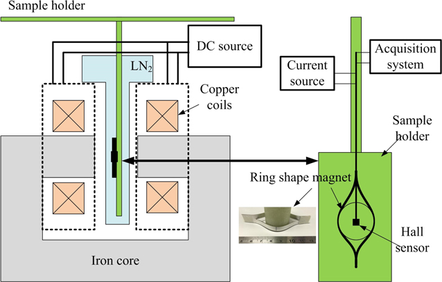
Figure 3. The magnetization test rig for the ring-shape YBCO magnet.
Download figure:
Standard image High-resolution image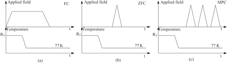
Figure 4. Three different magnetization processes: (a) field cooling (FC); (b) zero field cooling (ZFC); (c) multiple pulse field cooling (MPC).
Download figure:
Standard image High-resolution image2.3. Finite element model
To model the ring-shape YBCO magnet using the finite element software Comsol in an effective way, we use the previously validated 2D axial symmetrical H formulation [36–38]. The governing equation is shown in equation (1):

where H = [Hr; Hz] is the magnetic field and ρ is the resistivity. For air, we use ρ = 1000 Ωm; for YBCO, we use the E-J power law:

where n = 30, E0 = 100 μV m–1 and Jc(B) is the field-dependent critical current of YBCO [38]. Only the 1 μm thick YBCO layer is modelled to represent the YBCO ring. Since the 12 mm YBCO conductor has been split into two, each YBCO ring is 5.5 mm wide. The distance between two rings is the thickness of the YBCO conductor, which is 100 μm. From a 2D cross section view, the ring closest to the symmetrical axis is ring 1, while the outermost ring is ring 9.
3. Magnetization study
3.1. Field cooling and zero field cooling
Figure 5 shows the results of FC and ZFC. The modelling results match well with the experimental measurements, indicating that the 2D axial symmetrical model is a good representation of a ring-shape magnet. The FC process of the ring-shape YBCO magnet is similar to YBCO bulks and stacks of tapes. The trapped field increases linearly with the amplitude of the applied field before the magnet is fully penetrated. The maximum trapped field is 25 mT (Bp = 25 mT) with an applied field of 50 mT, which matches our field mapping modelling results in figure 2. The trapped-field rate is about 50% (trapped field rate = max trapped field/applied field). A further increase of the applied field does not affect the trapped field, because the ring-shape magnet has entered the saturated zone.

Figure 5. Experimental and numerical results of the sample ring-shape magnet based on FC and ZFC, where the ring diameter is 50 mm and the effective HTS width is 5.5 mm for the ring.
Download figure:
Standard image High-resolution imageFor the YBCO bulks and stack of tapes, when the applied field is below Bp, the final trapped field equals the applied field. The trapped-field rate is 100% in theory, but for the ring-shape HTS magnet in the FC process, the rate varies. Our study indicates that the trapped-field rate of the ring-shape magnet is affected by both the inner diameter of the magnet and the HTS tape width. Figure 6(a) shows how the HTS tape width affects the FC trapped-field rate. Basically, the wider the tape, the higher the rate. The readers are reminded that the tape width mentioned here is not the width of the YBCO tape being cut. Instead, it is defined as the width of the ring bar. In this case, it is 5.5 mm due to the 1 mm split loss in the centre, corresponding to a trapped-field rate of 50%. If a 40 mm HTS tape is used to build the ring-shape magnet, the trapped-field rate can reach 80% on the assumption that the inner diameter of the magnet is 5 cm. Figure 6(b) shows how the trapped-field rate changes with the inner diameter of the magnet. The larger the magnet diameter, the lower the trapped-field rate. The maximum rate can be 100% when the inner diameter is smaller than 1 cm.

Figure 6. The trapped-field rate of the ring-shape magnet in the FC process: (a) the influence of the tape width (the inner diameter of the magnet is 5 cm); (b) the influence of the inner diameter of the magnet (the HTS tape width is 5.5 mm).
Download figure:
Standard image High-resolution imageThe ZFC result in figure 5 shows a unique feature of the ring-shape magnet. It was noticed that there are three zones in the ZFC process according to the magnitude of the applied field. When the applied field is smaller than Bp (25 mT in this case), there is a shielding zone which sees nearly zero trapped fields. This is because the applied field has been fully shielded by the YBCO ring, so the magnet centre sees and traps very small magnetic fields. When the applied field is higher than Bp, it enters the linear zone, where the final trapped field increases linearly with the increase of the applied field. When the applied field reaches four times the Bp, it is the saturation zone where the trapped field remains as Bp.
To help understand the uniqueness of the three ZFC zones, the current distributions of each YBCO ring during the ZFC process are plotted in figure 7. For an applied field of 10 mT, the outermost ring (ring 9) and the second outermost ring (ring 8) have opposite current directions, which is the reason why nearly zero trapped field was measured at the centre of the magnet. The opposite current directions suggest that there is a shielding effect due to the applied magnetic field. Therefore, it is called the shielding zone (Bapply < Bp). A similar situation is found for an applied field of 20 mT. When Bapply is higher than Bp, it enters the linear zone where we start to see fully penetrated rings. For example, with the applied field of 30 mT, the outermost ring (ring 9) is fully penetrated while ring 8 and ring 1 are half penetrated. The rest of the rings are still in the shielding status. A further increase of the applied field sees more rings enter full penetration or half penetration status, which results in an increase in the trapped field. When Bapply exceeds 100 mT (four times the Bp), all the YBCO rings are fully penetrated with the same current distribution, which is the so-called saturated zone.
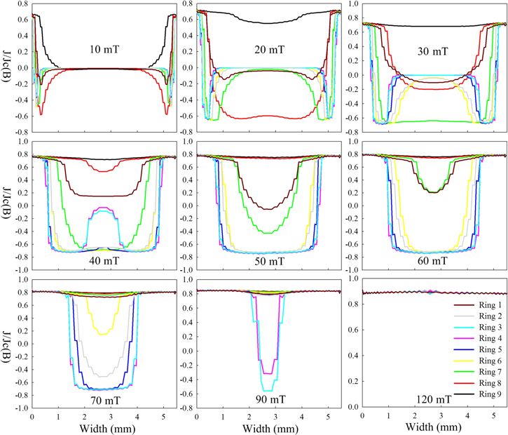
Figure 7. Calculated current distributions of all YBCO rings during ZFC. The applied fields of 10 mT and 20 mT belong to the shielding zone, 30–90 mT belongs to the linear zone, and 120 mT belongs to the saturated zone.
Download figure:
Standard image High-resolution image3.2. Multiple pulse field cooling
Multi-pulse magnetization techniques have been experimentally proven to improve the trapped field of the HTS bulk effectively. The multi-pulse technique includes successive pulsed field application (SPA), an iteratively magnetizing pulsed field method with reduced amplitude (IMRA), and a multi-pulse technique with step-wise cooling (MPSC) [39, 40]. We performed MPC tests for our ring-shape YBCO magnet. As explained previously, there are three zones in the ZFC process based on the magnitude of the applied field. So we did three MPC tests with the applied field in the shielding, linear and saturated zones respectively. The experimental results are shown in figure 8.
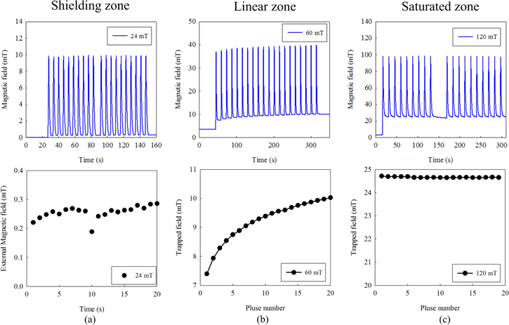
Figure 8. Measured magnetic fields in the MPC process: (a) shielding zone MPC, applied field 24 mT; (b) linear zone MPC, applied field 60 mT; (c) saturated zone MPC, applied field 120 mT.
Download figure:
Standard image High-resolution imageFigure 8 shows the measured magnetic field (trapped field from the ring plus the applied field) during the MPC process. The applied field is a programmed triangular pulse with controllable ramp-up rates (0–120 mT s−1) and a constant ramp-down rate (18 mT s−1).
Figure 8(a) shows the MFC process with an applied field in the shielding zone (24 mT). As discussed previously, the trapped field is very small (0.2–0.3 mT). Figure 8(b) shows that the trapped field increases during the MPC process with an applied field in the linear zone. In 20 pulse cycles, the trapped field increases from 7.3 mT to 10 mT. The trapped field growth rate slows down with consecutive increases of pulse cycles. Figure 8(c) shows that the trapped field saturates during the MPC process with an applied field in the saturated zone. We notice a small decline in the trapped field, which is due to the flux creep.
We are interested in the accumulation of the trapped field in the linear zone, which indicates that a relatively small applied field can be used to magnetize the ring-shape magnet in the MPC process and gradually build up the trapped field. To further understand the reason behind this accumulation, we plot the current distributions of each YBCO ring during the MPC process in figure 9. With an applied field of 60 mT, ring 8 and ring 9 (the outermost two rings) are fully penetrated, so their current distributions show little change in the MPC process. Ring 1 and ring 7 are half penetrated after the first pulse cycle, and the penetration areas gradually increase in the following pulse cycles. After the 5th pulse cycles, ring 1 and ring 7 become fully penetrated, and their current stays the same for the subsequent pulse cycles. Starting from the 5th pulse cycle, the applied field starts to penetrate ring 2 and ring 6. Therefore, the currents in rings 2 and 6 start to increase. This continuous penetration by MFC leads to an accumulation of total currents flowing in the magnet, which leads to the accumulation of the trapped field.
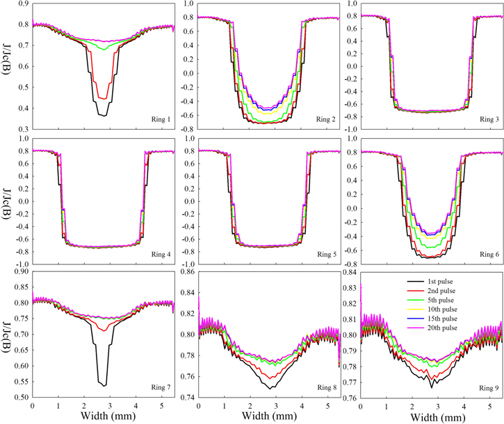
Figure 9. Calculated current penetration in the YBCO rings during the MPC process with an applied field of 60 mT.
Download figure:
Standard image High-resolution image4. Demagnetization
Demagnetization is an important issue for the application of HTS trapped-field magnets. For practical applications, the demagnetization rate of trapped- field magnets needs to be estimated to determine whether or not re-magnetization is required. The demagnetization of 2G HS bulks and stacks of YBCO tapes has been studied extensively, with both perpendicular and parallel magnetic fields [41–44]. Strategies to suppress demagnetization have been proposed using shielding rings [45, 46].
Here we report the demagnetization measurements of the ring-shape YBCO magnet. Figure 10 illustrates the three directions of the demagnetization field applied to the sample. Figure 10(a) shows positive perpendicular field demagnetization (the demagnetization field is perpendicular to the ring plane). Positive demagnetization indicates that the demagnetization field is in the same direction as the trapped field. Figure 10(b) shows the negative perpendicular field demagnetization. Negative demagnetization indicates that the demagnetization field is in the opposite direction of the trapped field. This is a very common situation in HTS machine applications, where the ring magnet provides the rotor magnetic field while the demagnetization field comes from the stator current. Figure 10(c) shows parallel demagnetization, where the demagnetization field is in a parallel direction to the ring plane.
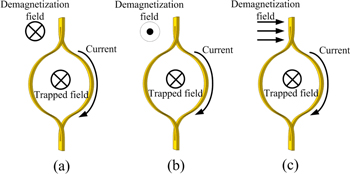
Figure 10. Three types of demagnetization: (a) positive perpendicular demagnetization; (b) negative perpendicular demagnetization; (c) parallel demagnetization.
Download figure:
Standard image High-resolution imageFigure 11(a) shows the measured magnetic field in the magnet centre and the trapped field in a positive perpendicular demagnetization process. The trapped field is not affected by demagnetization, because the slight decay rate is due to the flux creep in the HTS rings. Figures 11(b) and (c) show the measured magnetic field in the magnet centre and the trapped field in negative perpendicular demagnetization processes, where the demagnetization field is in the opposite direction of the trapped field. Both cases show a certain degree of demagnetization. The demagnetization effect of the first cycle is the strongest and then it gradually reduces. As shown in figures 11(b) and (c), the first demagnetization cycle forces the trapped field to drop by a ratio of 27% and 11.5% respectively. In comparison, the subsequent 29 demagnetization cycles forced the trapped field to drop by a ratio of 24.2% and 19% respectively.
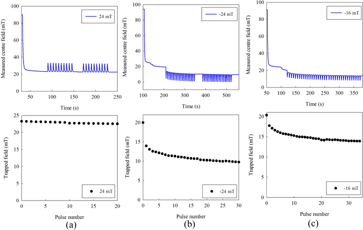
Figure 11. The measured trapped fields of the sample in perpendicular demagnetization: (a) positive demagnetization with a 24 mT magnetic field; (b) negative demagnetization with a 24 mT magnetic field; (c) negative demagnetization with a 16 mT magnetic field.
Download figure:
Standard image High-resolution imageTo understand the mechanism of demagnetization, we plot the current distributions in each ring based on 24 mT negative perpendicular demagnetization (nine cycles in total), as shown in figure 12. The magnet is fully penetrated before demagnetization; therefore, all the HTS rings have the same current distribution (the black line). In the first demagnetization cycle, all the HTS rings see a significant reduction in current, corresponding to the sharp drop of the trapped field. From the second cycle, only the outermost rings (rings 1, 8 and 9) show current reductions, because they serve as the shielding layers for the middle rings. This explains why the demagnetization effect slows down after the first cycle.
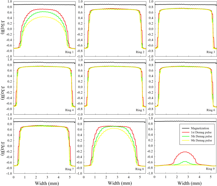
Figure 12. The calculated current distributions in the YBCO rings during a 24 mT negtive perpendicular demagnetization process.
Download figure:
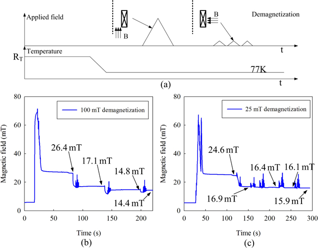
Standard image High-resolution imageFigure 13(a) shows the experimental procedure of a parallel demagnetization process. The ring-shape magnet was first magnetized by a ZFC to full penetration status. Then, the sample holder was rotated by 90 degrees, so that the applied field was parallel to the ring plane. The demagnetization was then carried out by applying multiple triangular waveforms.
Figure 13. The parallel demagnetization process of the sample with different field magnitudes: (a) the experiment process; (b) measured magnetic field with a 100 mT parallel field; (c) demagnetization with a 25 mT parallel field.
Download figure:
Standard image High-resolution image
Figures 13(b) and (c) show the measured centre magnetic fields with 100 mT and 25 mT parallel demagnetization respectively. When the first cycle of the 100 mT parallel field is applied, the trapped field decreases from 26.4 mT to 17.1 mT by a ratio of 35%. It then gradually drops by 8.7% in the second and third cycle respectively. The demagnetization rate slows down with the increase of demagnetization cycles. As shown in figure 13(c), after a 31.3% drop in trapped field in the first demagnetization cycle, the trapped field further decreases only 4% in the next three cycles. Theoretically, the parallel demagnetization field is perpendicular to the HTS tape surface. So, the current loops in the a-b plane can be induced in the outermost HTS rings to shield the demagnetization field, leading to a complete rearrangement of the current in the outermost rings and a significant reduction of the trapped field during the first demagnetization cycle.
5. Conclusion
This paper reports our latest study on a new type of 2G HTS trapped-field magnet: the so-called ring-shape magnet. The new magnet is very promising in large-scale applications, where they could replace permanent magnets, e.g. in HTS trapped-field machines or MRI devices. As a fundamental study paper, this paper focuses on the magnetization and demagnetization mechanisms of the new magnet, and tries to prove its great potential properties for industrial applications. The unique magnetization features have been identified and quantified for this new type of HTS magnet, and hopefully this information can be used as a guideline in industrial magnetization techniques. Our findings can be summarized as follows:
- In the FC study, it has been identified that the percentage of applied magnetic field that can be trapped in our sample is 50%. This can be further improved to nearly 100% by modifying the tape width and inner diameters.
- In the ZFC study, it has been identified that there are three different zones based on the relationship between the applied field and the trapped field, namely the shielding zone, linear zone and saturated zone. A flux accumulation effect was observed in the linear zone using MFC methods, which provides a possible way of magnetizing the magnets using a relatively small external magnetic field.
- In the demagnetization study, the new magnet is subjected to significant trapped-field reduction during the first cycle of demagnetization. Because individual HTS rings are used to construct the magnet, the outermost and innermost rings serve as shielding layers for the demagnetization field, which help to slow down the demagnetization rate in subsequent cycles.
Acknowledgments
Dr Min Zhang thanks the support from the EPSRC grant EP/P002277/1 and the Research Fellowship of Royal Academy of Engineering.