
Abstract
Superconducting technology applications in electric machines have long been pursued due to their significant advantages of higher efficiency and power density over conventional technology. However, in spite of many successful technology demonstrations, commercial adoption has been slow, presumably because the threshold for value versus cost and technology risk has not yet been crossed. One likely path for disruptive superconducting technology in commercial products could be in applications where its advantages become key enablers for systems which are not practical with conventional technology. To help systems engineers assess the viability of such future solutions, we present a technology roadmap for superconducting machines. The timeline considered was ten years to attain a Technology Readiness Level of 6+, with systems demonstrated in a relevant environment. Future projections, by definition, are based on the judgment of specialists, and can be subjective. Attempts have been made to obtain input from a broad set of organizations for an inclusive opinion. This document was generated through a series of teleconferences and in-person meetings, including meetings at the 2015 IEEE PES General meeting in Denver, CO, the 2015 ECCE in Montreal, Canada, and a final workshop in April 2016 at the University of Illinois, Urbana-Champaign that brought together a broad group of technical experts spanning the industry, government and academia.
Export citation and abstract BibTeX RIS

Original content from this work may be used under the terms of the Creative Commons Attribution 3.0 licence. Any further distribution of this work must maintain attribution to the author(s) and the title of the work, journal citation and DOI.
Introduction
The first task was to understand the state-of-the-art. Information related to key performance metrics has been collected and described qualitatively in the first two sections of this paper. Key metrics of known machines are summarized in the appendix, with details available in the references cited. This information was then taken as the baseline to project potential advances and estimate improvements in the key performance metrics over the next few years. Ongoing technology efforts, expected progress, and any known timelines served as inputs. Advances in enabling technologies, such as conductors and cryocoolers, and their impact on machine performance in the opinion of experts were also captured. These are compiled and reported in the later sections.
Two specific applications served as motivation for this roadmap exercise and provide a focus for the technical discussions: future electric airplanes and large offshore wind turbines. Key requirements of the former include high power density and high efficiency. Requirements for the latter include high torque density, efficiency and low cost. These are features traditionally associated with superconducting machines—and make them an attractive technology option to consider. Many other applications are being pursued by a number of research groups, and these may have their own unique requirements and trade-offs, but we believe much of the discussion in this document could apply broadly where size and weight are a consideration.
Aircraft applications
NASA's Fixed Wing Project (currently the Advanced Air-Transport Technology Project) has defined goals for the next three generations of aircraft for commercial aviation in four key areas of reducing noise, fuel burn, emissions and field length [1]. Table 1 outlines the goals for each generation, with N + 1 referring to the next generation of airplanes beyond those currently in production, and N + 2 and N + 3 referring to the two subsequent generations.
Table 1. NASA subsonic transport system-level metrics [1].
| N + 1a Technology benefits relative to a single-aisle reference configuration | N + 2a Technology benefits relative to a large twin-aisle reference configuration | N + 3a Technology benefits | |
|---|---|---|---|
| Noise | −32 dB | −42 dB | −71 dB |
| LTO NOx emissions | −60% | −75% | better than −75% |
| Aircraft fuel burn | −33% | −50% | better than −70% |
| Field length | −33% | −50% | exploit metroplexb concepts |
aTechnology Readiness Level for key technologies = 4–6 bConcepts that enable optimal use of runways at multiple airports within the metropolitan areas
The N + 3 goals are very challenging and would require disruptive technology beyond current trends in the aviation industry. One approach proposed by NASA being explored by various groups is turboelectric distributed propulsion [1–3]. A NASA internal team studied a 300-passenger Boeing B777-200LR on an intercontinental mission of 7500 nautical miles (13 890 km) with a cruise speed of Mach 0.84 and a 118 100 lb (∼53 570 kg) payload. They concluded that a hybrid wing-body aircraft, as shown in figure 1, combined with a turboelectric distributed propulsion system, is able to reduce the mission fuel burn by 70–72% from the baseline without compromising payload, range or cruise speed. This is accomplished by using an electrical drive system that decouples the power-producing parts of the system from the thrust-producing parts. Fifteen electric-motor driven turbofans were located in a continuous nacelle to maximize the amount of boundary layer ingested by the system. Two large turbo-generators that produce the power to run the fans were located at the wing tips, where they would receive undisturbed freestream air.

Figure 1. Schematic of a turboelectric propulsion system, highlighting required electrical machines. Reproduced with permission from [1].
Download figure:
Standard image High-resolution imageA key technology gap in bringing this concept to practice is the availability of flight-weight motors, generators and transmission lines. The assumptions made in system-level studies of these concepts could serve as the initial requirements for motor and generator technology to make the electrification of large commercial aviation feasible. The ultimate requirements would be finalized through an iterative process based on available component-level technologies and system-level trade-offs. Table 2 gives motor and generator ratings and design goals that have been extracted from the above studies to serve as a baseline for superconducting machine technology assessment.
Table 2. Electrical machine requirements for an example turboelectric-aircraft concept [1].
| Generators | Motors | |
|---|---|---|
| Number of units | 2 | 15 |
| Power rating | 30 000 hp (22.4 MW) | 4000 hp (3 MW) |
| Assumed weight | 2200 lb (1000 kg) | 520 lb (236 kg) |
| Assumed efficiency | 99.3% | 99% |
| Speed | 6500 rpm | 4500 rpm |
The industry is also considering other opportunities for inserting electrical propulsion technologies into airplanes. A recent study focused on a single-aisle turboelectric commercial transport with fuselage boundary layer ingestion [4] designed for 154 passengers with a 3500 nautical mile range, at a cruise speed of Mach 0.7. Compared to the baseline aircraft with equivalent N + 3 technology, it is projected to achieve a 7% fuel (and energy) reduction for a 900 nautical mile mission and a 12% fuel (and energy) reduction for 3500 nautical miles. This airplane design, as shown in figure 2, calls for a 2.6 MW motor fed from two 1.45 MW generators and assumes a 90% electric drive system efficiency.
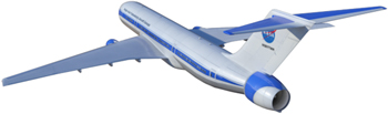
Figure 2. Single-aisle turboelectric commercial transport with fuselage boundary layer ingestion. Reproduced with permission from [4].
Download figure:
Standard image High-resolution imageIn Europe, the European Commission has set goals in its roadmap report 'Flightpath 2050—Europe's Vision for Aviation', including a 75% reduction of aircraft CO2 emissions, a 90% reduction of nitrogen oxides and a 65% reduction in noise levels relative to the standards of the year 2000. Airbus, along with partners Rolls-Royce and Cranfield University, has announced plans for an electrically distributed propulsion system concept, the 'E-Thrust', for a regional aircraft (approximately 90 seats and two hours flight time) [134–136]. This concept utilizes a distributed propulsion system with six electric fans distributed along the wing span. One gas-powered generator provides electrical power for the six fans and for recharging the batteries. With this arrangement, an effective by-pass ratio of over 20 is achievable, leading to significant reductions in fuel consumption and emissions.
In summary, high power density electrical motors and generators at the MW scale are key enablers for future electric aircraft. The above referenced system configurations can serve as the initial specifications for electric machine development. Final ratings will be found through an iterative process between component-level and system-level technology advancement.
The National Academies of Sciences, Engineering, and Medicine recently released a report highlighting electrical-system component requirements for a broad range of hybrid and electric propulsion systems [5]. Table 3 summarizes key target metrics to make these systems viable.
Table 3. Electrical-system component performance requirements for parallel hybrid, all-electric and turboelectric propulsion systems [5].
| Aircraft requirements | Electric system (including power electronics) | Battery | |
|---|---|---|---|
| Power capability (MW) | Specific power (kW/kg) | Specific energy (Wh/kg) | |
| General aviation and commuter | |||
| Parallel hybrid | Motor <1 | >3 | >250 |
| All-electric | Motor <1 | >6.5 | >400 |
| Turboelectric | Motor and generator <1 | >6.5 | n/a |
| Regional and single aisle | |||
| Parallel hybrid | Motor 1–6 | >3 | >800 |
| All-electric | Motor 1–11 | >6.5 | >1800 |
| Turboelectric | Motor 1.5–3; Generator 1–11 | >6.5 | n/a |
| Twin aisle | |||
| All-electric | Not feasible | ||
| Turboelectric | Motor 4; generator 30 | >10 | n/a |
Wind turbine applications
It is a general trend that superconducting rotating machines are more likely to be commercially viable at large sizes and powers because the necessary added cryogenic subsystem then becomes a smaller portion of the total machine weight and cost. For wind power generators, larger power generators are almost always employed in offshore turbines. There are some advantages for offshore wind generation: the wind blows more steadily near the coast where there is a higher population, reducing transmission costs, and the land offshore is usually cheaper than on the coast. However, there is added outlay for placing wind generation offshore—the towers and platforms are much more expensive to build, and the electricity must be taken to shore by underwater cable systems. Hence, the electricity generated by offshore wind is so far considerably (∼3X) more expensive than onshore wind, and this has limited offshore wind generation. For onshore wind, almost all generation is by generators connected via gearboxes to the blades and hence turning much faster, which reduces their size and weight considerably. For offshore wind, the difficulty of maintenance has encouraged manufacturers to use direct-drive generators to avoid gearbox maintenance. This greatly increases the generator size and torque loads at their slow tuning speeds (e.g. ∼10 rpm). Thus, it is size and weight reduction that is potentially offered by superconducting direct-drive generators, making them appealing for offshore wind. Present offshore direct-drive generators use permanent magnet (PM) rotors in power ratings to 8 MW.
Currently, world offshore wind capacity is about 12 GW, most of which is in northern Europe. This is only about 3% of the present world wind generation capacity [6]. Market projections indicate that the cumulative offshore capacity will rise to 29 GW by 2020 [7]. Producing a superconducting offshore direct-drive generator is likely to be an expensive proposition for any manufacturer, since it would be a very new machine with many high-risk items. Hence, two factors figure strongly in any decision to do so: the calculated benefits of such a machine on the wind levelized cost of energy (LCOE) and the non-recurring engineering (NRE) costs for developing a very new machine type such as superconducting, which is likely to be higher than that for an extension of an existing machine type. This NRE must be paid back by the projected sales and market size for the new machine. A further consideration is the prototyping and testing necessary to prove reliability for market acceptance of a new technology.
The winning commercial equipment for wind electricity generation is decided by the LCOE generated by that equipment. Calculations of COE can be quite complex, but certain factors are apparent. First, the generator is only one piece of equipment among many in the overall wind generation system; towers, foundations, blades, power transmission, and installation are also very important. Therefore, any superconducting wind generator can only succeed when it compares favourably to all the other options (e.g. permanent magnet, wound field, geared generators) on an LCOE basis. Generator factors important in this comparison are: costs associated with capital, operation and maintenance, installation, and reliability. Size and weight reductions in superconducting generators may have benefits in reduced tower, foundation, or transportation costs. As stated above, superconducting generators are more likely to be competitive at high powers such as those which are used offshore. However, they must succeed in total COE comparisons to win.
Discussion
As will be seen from the following sections, it is clear that superconducting machines hold great promise for extreme reduction in machine size and weight. Risks must be reduced and technology readiness level (TRL) advanced, especially for some of the more aggressive designs such as fully superconducting machines and high-field air-core topologies, before they are ready for system integration.
As described earlier, a number of approaches can lead to even higher specific power and efficiency than is possible today.
- A.Fully superconducting machines have the potential to attain the highest efficiency by minimizing losses in both the field and armature windings. To attain these levels of losses, however, significant advances in ac-capable superconductors must be made. Since partially superconducting machines are already projected to achieve 99% efficiency with most losses in the 'conventional' ac windings, to obtain superior efficiency, the ac losses in a superconducting armature must be significantly less than 0.1% of the machine rating. This has to be achieved within 'ac' flux in the order of 103 Tesla/second to be competitive in power density with partially superconducting machines.
- B.Partially superconducting machines also have potential for increased specific power with complete elimination of ferromagnetic components and higher operating flux density. For the full entitlement of these topologies to be realized, high temperature superconductors (HTS) capable of high fields at high temperatures need to be matured and composite structures developed to replace relatively heavy vacuum vessels and torque tubes.
- C.Machines built with bulk superconductors are another exciting area of active research, though they are currently at a lower TRL. Plans are underway to demonstrate these machines at the tens of kW power ratings. Improved bulk superconductors capable of operation at liquid nitrogen temperatures and ways to magnetize the bulks at high fields would further increase the potential for these machine types.
Good progress has been made by industry in recent years on:
- Unit length of HTS conductors (up to ∼100 m)
- Quasi-industrial production (despite the absence of a steady wire demand/market)
- Critical current at lower temperatures and moderate magnetic fields
- Steepness of U-I curve (n-value) : U/U0 = (I/Ic)n; Ic representing the critical current, so a high n-value indicates a sharp and steep transition from the superconducting to the normal conducting state
- Pinning improvement
- Specific cost decrease ($/kAm)
- Description of 'value added to product'.
For the promised benefits of superconducting machines to be achieved, further progress must be made in:
- Unit length of HTS conductors (500 m+)
- Mechanical properties
- Critical current at high temperatures and magnetic fields
- Supporting materials (insulation, mechanical support)
- Composite structures
- Quench detection and control
- High-current brushes
- Cryostats
- Dedicated cooling technology/coolers adopted to cooling power needs
- Specific cost ($/kAm) at operating point (temperature and magnetic field)
- ac loss reduction
- Description of system-level 'value add'
- Awareness and training of engineers in conventional technologies
- Creating an 'economy of scale' effect by (small, but steady) market demands (this could finally lead to a wire price in the order of 10 $/kAm or less [79]).
Figure 3 illustrates how one of the key metrics, the specific torque, has increased over the last couple of decades, and how it can be advanced further with some of the technologies being pursued. The reference designs are listed in the appendix. The projected timeline is an estimate assuming ongoing programs proceed to technology demonstrations. While specific torque is a proxy for specific power, and a metric closely related to the electromagnetic capability of the machine, trade-offs will have to be made in high-speed machines to meet and exceed the high specific power requirements summarized in table 3.

Figure 3. Projected torque density advances.
Download figure:
Standard image High-resolution imageSuperconductor technology has been amply demonstrated in many rotating machine applications—both small and large in sizes and ratings. Save for reliability data, all demonstration projects have achieved their stated goals. However, each application has its own specific requirements. For example, electric utility and industrial applications value low product cost, high efficiency and reliability. On the other hand, defence application attributes include compact size and low mass, high reliability and affordable cost. Adoption of this technology is not free of challenges. The most significant could be from currently used technologies, which are also improving by the employment of more advanced materials and manufacturing. Introduction of superconductor technology also requires the absorption of NRE costs, which may present a significant challenge. Early adopters will be in areas that are beyond the capabilities of current technologies, as magnetic resonance imaging (MRI) magnets have been. For example, all-electric planes would require very high specific power density motors and generators. Superconductor technology could be attractive if available at an affordable cost and acceptable reliability. HTSs are less prone to sudden quenching, but they are costly and more difficult to protect if they quench. Also, refrigerator systems tend to be costly, bulky and heavy. Since each application has unique requirements and objectives, it is difficult to suggest a single desirable price for superconductors. The same argument applies to the cooling system. However, a general statement could be made that for superconductor technologies to be attractive, it may be necessary to reduce the system cost by a factor of ten for utility and industrial applications [139] and by five for defence applications. Nevertheless, it should be realized that product cost is also a strong function of market size. Larger markets will help drive down the cost of superconductor technology. Some real-life applications are expected to emerge during the next decade.
For commercial applications of developing product lines using superconducting technology, supply chains of superconductors and other components for mass production need to be developed. Additional operational prototypes for industrial applications should be employed to prove performance reliability. Private and public-sector funding must be available to mitigate the risks of validating the technology for industrial commercial applications. The insertion of new cryogenic/superconducting sub-systems into conventional machines could be a cost-effective way to reduce risks in an incremental manner.
1. Overview/Configuration
Swarn Kalsi
Kalsi Green Power Systems
Status
Interest in superconducting machines focuses on several aspects, depending on the intended applications. For example, applications of motors and generators in power utilities prefer higher efficiency and ease of operation while operating on an electric grid; mobile systems employed by aerospace and naval industries prefer compact, lightweight designs with attractive efficiency; and wind-farm applications desire attributes like high efficiency, compact size and low weight. All applications stress the importance of low maintenance and high reliability during operation.
The application of superconductors to rotating machines began in the late 1960s [8] following the availability of multi-filamentary NbTi superconductors. Since these superconductors were suitable for carrying only dc, the first applications were envisioned for replacing dc field windings in rotating machines. The most attractive were large ac synchronous motors, generators, and homopolar dc machines.
Magnetic field strength in the air-gap of conventional machines is usually limited by the saturation of iron teeth on the rotor and stator. However, the high-current-carrying capability of superconductors made it possible to create much higher air-gap field strength using a small volume of field winding, and with little energy loss. To the first order, resistive losses are about equal for the field and armature windings. Thus, a replacement of copper field winding (representing nearly half of total copper losses) with superconducting windings held the promise of improved efficiency (0.5–1%). In initial applications, field winding on the rotor was carried in non-magnetic steel, and the stator (armature) winding employed no magnetic teeth. The environment surrounding the machines was shielded from the ac stray field on the stator with magnetic iron yokes or conductive shields. Large synchronous generators were conceptualized by General Electric [9], Westinghouse [10], Super-GM [124, 125], and others around the world using this topology. Super-GM advanced the project most during the 1990s by testing a 70 MVA generator with three different rotors employing three different NbTi field windings. Nevertheless, none were found to be economically attractive due to technical issues. These included: (1) high cost and poor reliability of the 4.2 K cooling system, (2) stability issues relating to a small temperature operating range (4.2 K to 5.5 K), (3) protection of NbTi field windings from harmonics fields generated by the stator during normal and abnormal operations, and (4) the complications and costs of building air-gap stator windings. As shown in the appendix, many attempts to make this technology commercially viable bore no fruit.
Likewise, dc homopolar machines were also attempted worldwide, beginning with significant development work by Appleton in England [11] in the late 1960s. Similar efforts continued in the United States [12] until the first decade of the 21st century. These machines were mostly handicapped by insurmountable problems associated with brushes needed for current transfer back and forth to the rotor. Most of the development work ceased by the early to mid-1980s on machines employing low-temperature NbTi superconductors (LTS).
The discovery of high-temperature superconductors (HTS) in 1986 provided an impetus to develop a variety of machines based on these new superconductors. HTS conductors operating at much higher temperatures (between 25 K and 77 K) simplify refrigeration-cooling systems, and the HTS winding operating-temperature range is much wider. The higher thermal heat capacity of materials employed in the windings also enables absorption of much larger transient thermal loads with little temperature rise. As shown in the appendix, many full-scale motors and generators, both low-speed and high-speed, have already been demonstrated worldwide using this HTS technology.
Current and future challenges
Many motors and generators have been attempted (or under development) using the following configurations:
- Superconducting field winding with conventional (copper) stator winding
- Ultra-low-speed generators for wind-farm applications (up to 10–15 MW at ∼10 RPM)
- Low-speed motors for ship propulsion (up to 36 MW, 100–250 RPM)
- Medium-speed motors and generators (up to 10 MW, 1800–3600 RPM)
- High-speed motors and generators (>1 MW at 7000–30 000 RPM)
- Bulk superconductors operating as permanent magnets
- AC homopolar machines employing superconducting field winding and conventional ac windings for very high speed (7–50 kRPM)
- Several non-public attempts are underway to employs HTS for ac stator windings
- DC homopolar machines for ship propulsion
Significant work is in progress around the world as shown in the appendix. Because of problems associated with high-current brushes, dc homopolar machine development has essentially stopped.
Two popular types of electric rotating machines are synchronous and induction. A synchronous rotating machine has two windings: an ac winding located in the stator and a dc field winding located on the rotor. This is the most common configuration, although the two winding locations are interchangeable. An induction motor has a squirrel cage or three-phase wound winding on the rotor. The rotor winding carries ac at the slip frequency; the rotor frequency is equal to the line frequency when the slip is equal to 1 (rotor stationary) and the slip frequency (typically <5% of the line frequency) when the motor is operating at its nominal speed. Induction motors are popular in industry for lower ratings (<5000 hp), but synchronous motors are preferred in larger sizes. Moreover, induction motor windings, both on rotor and stator, experience ac currents and are currently not good candidates for superconductor windings. Superconductor losses are negligible only when the motor carries dc. These losses in the ac environment are quite large and difficult to remove economically. Because of the currently high cost of superconductors and cooling systems, the primary applications of these machines are in large sizes (>1000 hp), like generators and motors for pump and fan drives for utility and industrial markets, large ship drives, and wind-farm generators.
Kalsi describes the configuration of a typical ac machine and its design process [13]. The rotating HTS field winding creates an ac magnetic field in the copper armature winding. The magnitude of this field is typically twice that of a conventional machine. Usually, the HTS machine has an air-core (i.e. non-magnetic) construction on the rotor and no iron teeth in the stator, enabling the air-gap field to be increased without the core-loss and saturation problems inherent in laminated-iron stator and rotor cores. The copper armature winding is placed adjacent to the air-gap. Under steady-state operation, the rotor spins in sync with the rotating field created by the three-phase armature currents, and the superconducting field winding experiences only dc magnetic fields. Under load or source transients, however, the rotor moves with respect to the armature-created fields, and it experiences ac field harmonics. An electromagnetic (EM) shield, usually located between the HTS coils and the stator winding shields the HTS field winding from these ac fields. A refrigeration system, which uses cold circulating helium gas (or another suitable gas) in a closed loop, maintains the HTS field winding at cryogenic temperature.
The copper stator winding usually employs no magnetic iron teeth. In order to reduce eddy-current losses, the stator coils are fabricated with a copper litz conductor, consisting of small-diameter insulated and transposed wire strands. Because of a large effective air-gap (between field and armature coils), the back EMF in the air-gap stator winding is nearly a pure sine wave—the harmonic field components are much smaller than those observed in the conventional machines.
Advances in science and technology to meet challenges
Benefits of superconducting machines
Once HTS technology matures, it has the potential to offer significant benefits to both traditional utility/power and aerospace industries. Key attributes of HTS machines, across the board, are compact size, low weight and higher efficiency than conventional copper winding based machines. Below are the key benefits realizable by each industry.
Electric utility/power industry
Bulk power generation and utilization and pros/cons of HTS technology [14] as it applies to this industry are listed as follows.
Pros:
- Smaller size and weight
- Higher efficiency
- Low synchronous reactance (Xd) offers better system stability during operation on an electric grid.
- Low Xd also means much smaller voltage regulation as a function of load—an automated voltage regulator (AVR) could be eliminated or its operating range reduced.
- Machines could ride through transient disturbances on an electric grid without the support of an AVR.
- Higher efficiency at partial loads
- Operates as a condenser up to the rated capacity of armature coils
Cons:
- Low Xd, Xd' and Xd'' reactances cause large short-circuit currents, which require circuit breakers with high current-interruption capability.
- Compact and lightweight HTS machines have an inherently smaller moment of inertia of the rotor. This may inhibit the transient response of the machine to some extent.
- The refrigeration system must be reliable for maintaining the field winding at its intended cryogenic temperature during all normal and abnormal operational phases.
- The high cost of HTS and refrigeration systems pose a significant challenge for the commercialization of these machines.
Wind farm generators
Because of their low operating speed, these machines tend to be bulky and heavy. Such attributes make tower design complex and expensive. We note that tower cost is the highest component cost of a wind generator system. Applications of HTS to these machines could be very beneficial, especially for large generators located offshore [15]. Some pros and cons of such applications are listed as follows.
Pros:
- Compact and lightweight HTS machines could reduce tower size and complexity.
- Higher efficiency than conventional machine could offset higher cost of the HTS technology.
- Compact/lightweight attributes may make possible large machines (>10 MW rating) to be built and shipped fully assembled to the site, thus reducing installation time and cost at the site.
- Direct coupling to the turbine is enabled, eliminating the need for heavy and problematic gearbox.
Cons:
- High cost of superconductors and refrigeration system
- Reliability concerns of refrigeration system for machines located offshore
Ship propulsion
A ship system design is usually constrained by the large size and complexity of the propulsion system. This constraint could be removed by employing HTS technology that results in a much more compact and light propulsion system with higher efficiency than the conventional systems. These features were demonstrated by AMSC in building and testing a 36.5 MW, 120-RPM motor for ship propulsion [16]. The ship propulsion motors are usually low- speed machines (∼200 RPM) and are therefore bulky and heavy. Listed below are a few key pros and cons of employing ship-propulsion motors based on HTS technology:
Pros:
- HTS motors are much more compact and lighter weight (two to five times) compared to motors employing conventional technology.
- Higher efficiency (5%–10%), which is maintained down to almost 20% of the rated load
- Lower acoustic and structure-borne noise—an attribute considered important in naval ships
- HTS motor technology has been demonstrated by constructing and testing a 36.5 MW, 120 RPM motor by AMSC in 2007 (see appendix).
Cons:
- Compared with conventional induction motors, HTS motors are more expensive, primarily due to the high cost of HTS and the cooling system.
- The reliability of the cooling system is a key risk factor.
Aerospace motors and generators
Aerospace industries are looking for compact motors and generators for application to all-electric flying platforms. Generators operate at very high speeds (7–50 kRPM). Motor speed can range from direct-drives operating at a few thousand RPM to geared drives at speeds comparable to the generators. The most desirable attributes of these machines are compactness and light weight. Several programs are currently underway around the world. One of the key challenges is to supply power and coolant to the rotor turning at a high speed. GE built and tested a 1 MW, 10kRPM machine [17] using an ac homopolar topology (see appendix). The pros and cons of such machines are listed below:
Pros:
- Compact and lightweight with higher efficiency than conventional machines
- No active windings on the rotor
- Stator houses both field and armature windings, simplifying their mechanical support and cooling.
- HTS for the armature windings has the potential to make these machines even more compact and light.1
Cons:
- AC homopolar machines are theoretically larger in size than comparable heteropolar machines.
- HTS conductors capable of operating in a high frequency field (∼200–2000 Hz) are not yet available.
- Must minimize use of metallic components in order to reduce mass
Industrial applications
Large motors are usually employed in industry for pumping fluids such as water, oil, or natural gas, and for process-manufacturing in paper, steel and mining industries. The induction motors range in power up to tens of MWs and are used over a wide speed range (1–200 RPM) for direct-drive rolling mills and low-speed pumps, and high-speed (∼6000 RPM) compressor applications. However, wound field synchronous motors are often used in a low-speed range determined by the customer's specific requirements. Some synchronous machines are also operated as synchronous condensers for reactive power control. As an example, a superconducting synchronous condenser, 8 MVAR, 1800 RPM, was built and tested on the Tennessee Valley Authority (TVA) electric grid [18] next to a large arc-furnace facility (see appendix). The pros and cons of a medium-size superconducting machine are listed below:
Pros:
- Compact and lightweight with higher efficiency than conventional machines
- Because of characteristically low Xd, it is possible to operate an HTS machine over its entire stator rating while delivering leading or reactive power without impacting its dynamic stability.
Cons:
- In medium-size applications, the main impediment to the adaptation of HTS technology is the cost of HTS and its associated cooling system.
Concluding remarks
Superconducting motors and generators have been widely demonstrated for applications in areas such as electric power utilities, industrial systems, naval ship systems, all-electric aircraft systems, and wind farms. Most of the key technology issues have been resolved or are addressed at very high levels. Such superconducting systems are destined to play a very important role during the next two decades.
For example, technology is changing the world at a faster pace than ever before—changes encompass all aspects of our lives, i.e. leisure, employment, transportation, education, and more. Predictions for the next couple of decades include electric planes, high-speed trains and cars, and a multitude of robots relieving humans from the drudgery of hard labor and the boredom of routine tasks. All these technologies will need efficient electric power generation, distribution and utilization with a minimal carbon footprint. Electric power will be generated from renewable sources such as solar, wind, hydro and nuclear, and it will be transmitted and utilized with minimum losses. One key enabler will be superconductivity.
Currently, two major hurdles for wide adaption of superconductor-based technologies are the cost of superconductors and their cooling system, and workable superconductor mechanical properties. Government subsidies are needed to continue development in order to keep pace with this emerging technology.
2. Partially superconducting wound-field-synchronous
Haran Karmaker
TECO-Westinghouse
Status
The majority of technology demonstrations to date have been with partially superconducting technology for wound field winding synchronous (WFS) topology, because it is straightforward to use and achieves higher efficiency and lower weight than using copper field winding in conventional machines. As pointed out in the previous section, recent applications concentrated on HTSs as cooling systems for high-power rated machines have become feasible. This section will continue a review of the state-of-the-art following the review report in 2004 [14]. Torque requirements for power and speed ratings generally define machine size based on the current capabilities of superconductors in field winding. The benefits of developing HTS machines have been described in the previous section.
Current and future challenges
Various machine topologies have been investigated for a variety of applications covering high, medium, and low speeds. There have been technological advances in HTS technologies for these applications. GE reported the development of a high-speed HTS generator using a homopolar inductor alternator [17]. A review of high power density generators incorporating YBCO windings concludes that YBCO HTS conductors have demonstrated the best performance and are capable of meeting the requirements of high power density generators [19]. Siemens reported operational experiences on a 3600 RPM 4 MVA HTS generator [20]. The efficiency of the HTS generator (figure 4) was shown to be almost 2% higher (at 98.7%) than a conventional generator of the same rating. The weight and volume of the HTS generator are greatly reduced compared to a conventional generator shown in figure 5.
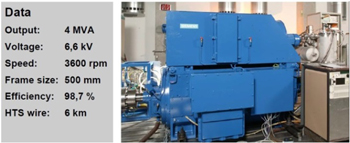
Figure 4. Siemens 4 MVA HTS generator. Reproduced with permission from the presentatation 'Development of HTS machines' to TU Darmstadt, 15 July 2009 and press picture of HTS-2-machine (press release 16 April 2009).
Download figure:
Standard image High-resolution image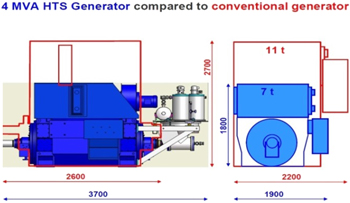
Figure 5. Size and weight comparison to conventional generator. Reproduced with permission from the presentatation 'Development of HTS machines' to TU Darmstadt, 15 July 2009 and press picture of HTS-2-machine (press release 16 April 2009).
Download figure:
Standard image High-resolution imageThe American Superconductor (AMSC) has demonstrated an eight-MVA SuperVAR [21] shown in figure 6 for the TVA transmission system. The HTS SuperVAR has proven to be an economic option for providing reactive compensation to a power system and is the first commercial application of HTS technology.
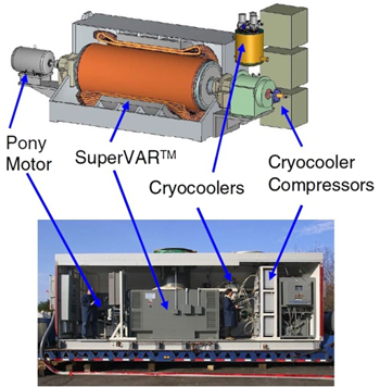
Figure 6. AMSC SuperVAR for TVA.
Download figure:
Standard image High-resolution imageAdvances in science and technology to meet challenges
A comparative study applying second generation (2G) HTS technology to a ship propulsion motor was carried out by TECO-Westinghouse [22] for a 3.6 MW 1800 RPM motor utilizing the stator of a conventional squirrel cage induction motor, shown in figure 7, operating on a US Navy ship. Figure 8 shows the conceptual HTS motor design. Table 4 shows the comparison of volume, power density and efficiency with a conventional induction motor operating on the ship with those of the PM and HTS 2G motors. The HTS 2G motor offers higher efficiency and power density than both induction and PM motors similar to those in figures 4 and 5.
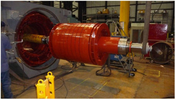
Figure 7. 3.6 MW 1800 RPM ship propulsion motor. © 2015 IEEE. Reprinted, with permission, from [22].
Download figure:
Standard image High-resolution image
Figure 8. A conceptual design of HTS propulsion motor. © 2015 IEEE. Reprinted, with permission, from [22].
Download figure:
Standard image High-resolution imageTable 4. Comparison of power density, volume and efficiency of HTS 2G propulsion motor with PM and induction motors.
| Type of motor | Power density (x100 kN/m^2) | Volume (m^3) | Efficiency (%) |
|---|---|---|---|
| Induction | 0.26 | 0.8 | 96.37 |
| Permanent magnet | 0.42 | 0.56 | 97.62 |
| HTS 2G field winding | 0.53 | 0.41 | 98.72 |
Wuhan Research Institute, China, demonstrated an HTS 1 MW propulsion motor [23]. Figure 9 shows the rotor for a four-pole 500 RPM HTS motor and test setup for full load testing.
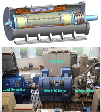
Figure 9. 1 MW HTS motor rotor and test setup.
Download figure:
Standard image High-resolution imageThe Research Institute of Science and Technology of Korea demonstrated a 10 kW 2G HTS air-core generator [24] for proof of concept. Figure 10 shows the test setup for successfully verifying their concept design. To prevent the degradation of the HTS wire by delamination, the authors used paraffin impregnation instead of epoxy. The rotor uses four racetrack double-pancake coils cooled to 30 K using neon gas.
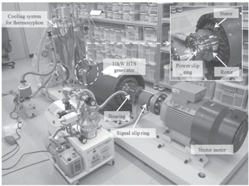
Figure 10. Test setup for 10 kW 2G HTS generator. © 2015 IEEE. Reprinted, with permission, from [24].
Download figure:
Standard image High-resolution imageConverteam (now GE) designed and constructed an HTS field winding with a goal to retrofit the rotor of an existing power station hydro-generator [25] rated 1.7 MW, 5.25 kV, 28 poles, 214 RPM for directly connecting to the power grid. Figure 11 shows the conceptual design of the retrofitted generator.
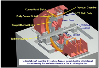
Figure 11. HTS hydro-generator.
Download figure:
Standard image High-resolution imageFigure 12 shows a picture of the hydro-generator rotor with HTS field windings. A rotating coupling using two concentric tubes, one rotating inside the other, is used to transfer cryogenic coolant from a stationary cryocooler to the rotating HTS field coils.

Figure 12. Hydro-generator retrofitted with HTS rotor.
Download figure:
Standard image High-resolution imageAMSC reported factory tests on a 36.5 MW HTS propulsion motor in 2007 [16]. Figure 13 shows the test stand including pony motors and a speed-reducing gearbox.
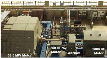
Figure 13. 36.5 MW HTS propulsion motor test stand.
Download figure:
Standard image High-resolution imageThere are numerous publications on direct-drive multi-MW rated synchronous wind-turbine generators [26–30]. There is no reported manufacturing or testing of a full-size machine. Some component parts have been successfully built and tested. Figure 14 shows the AMSC concept of the drive train [27]. Figure 15 shows a 2G HTS pole set built and tested by AMSC [27].
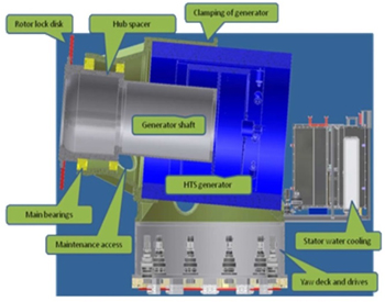
Figure 14. Drive train concept of 10 MW class wind turbine. © 2011 IEEE. Reprinted, with permission, from [27].
Download figure:
Standard image High-resolution image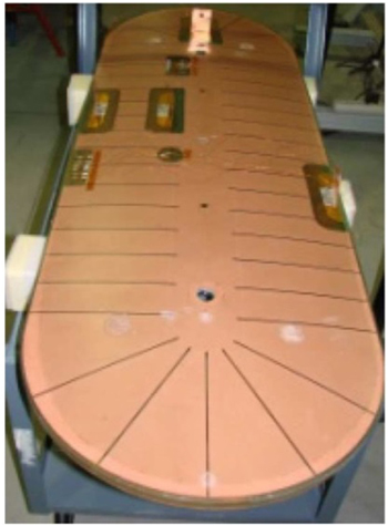
Figure 15. 2G HTS pole set built and tested. © 2011 IEEE. Reprinted, with permission, from [27].
Download figure:
Standard image High-resolution imageThe stator was designed using an iron core and Roebel transposed single-layer copper winding with half coils by TECO-Westinghouse. A manufactured and tested wound section of the full-length stator with the half-end turns brazed is shown in figure 16 [28].
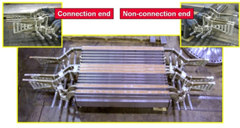
Figure 16. A section of wound stator for 10 MW class wind generator. © 2015 IEEE. Reprinted, with permission, from [28 ].
Download figure:
Standard image High-resolution imageA new 2G HTS conductor with a minimum of 4X improvement in current-carrying capacity over commercially available conductors was recently developed by SuperPower and the University of Houston [31]. The new conductor properties were used to develop design concepts for a 10 MW 8 RPM direct-drive wind generator by TECO-Westinghouse [29, 30]. The design was optimized by NREL for minimum LCOE [32]. Figure 17 shows the investigated design options—the iron-core salient-pole design shows the lowest cost. The selected design with the lowest cost is the heaviest [29].
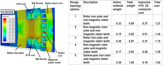
Figure 17. Concept design topologies for 10 MW wind generator with 4X 2G HTS. © 2015 IEEE. Reprinted, with permission, from [29].
Download figure:
Standard image High-resolution imageConcluding remarks
As described in this section, numerous advances in the application of partially superconducting wound-field synchronous machines have been made since the discovery of high-temperature superconductivity in 1986. Despite numerous demonstrations of HTS applications in electrical machines, there are still no known commercial electrical machines operating in the field employing HTS technology. Many government-supported programs have been initiated, completed, and are continuing with the aim of commercializing the technology. The main hesitation of industry acceptance for commercial product development is due to the fact that there is still a lack of suppliers of HTS conductors and other components needed for the mass production of electrical machines. The end user is also hesitant to accept the new technology because of its lack of reliability and field-operation data. The roadmap to the commercialization of HTS electrical machines is to develop robust manufacturing processes and supply chains for HTS, cryogenics, and related components. As the world population grows and demands increased clean-energy conversion equipment, the technology will eventually become commercial.
3. Fully superconducting machines
Kiruba Haran1, Philippe Masson2, Swarn Kalsi3 and Rod Badcock4
1University of Illinois, Urbana-Champaign
2University of Houston
3Kalsi Green Power
4Victoria University of Wellington
Status
Fully superconducting synchronous machines utilize superconductors for both field winding and armature winding. These types of machines are expected to be superior to the partially superconducting machines described above, because, in addition to those benefits, armature electrical loading can also be increased substantially, at least in theory, and a very high efficiency could be obtained by significantly reducing the armature Ohmic losses. This topology has been studied for decades [90] with limited success, but it is seeing resurgence with the emergence of ac-capable HTS conductors. An example configuration being pursued by NASA is shown in figure 18 [3]. The rotor coils are inside the white lozenge-shaped coil packs. The stator coils are represented by free-standing wires with connections terminated to the right of the figure.
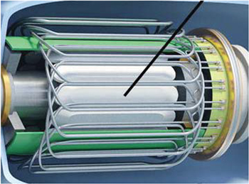
Figure 18. Schematic drawing of a fully superconducting electric machine. Reproduced with permission from [33].
Download figure:
Standard image High-resolution imageCurrent and future challenges
Lowering stator ac losses is a key challenge. These losses can be reduced by using a small diameter wire with twisted fine superconducting filaments embedded in a resistive metallic matrix, as shown in figure 19 [33]. The MgB2 filaments appear as black regions. The balance of the cross section is composed of a variety of normally conducting materials. Using 2G HTS, twisted filaments seem to be mandatory, too, to reduce ac loss [126]. Unfortunately, there are presently no technologies available to obtain such conductors except for cable concepts like CORC [127]. However, the feasibility and effectiveness of these approaches are yet to be proven.
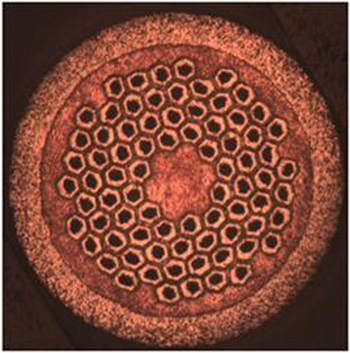
Figure 19. A 78-filament low ac loss MgB2 wire from Hyper Tech Research. Reproduced with permission from [34].
Download figure:
Standard image High-resolution imageAdvances in science and technology to meet the challenge
Three possible conductors are being considered for ac-armature winding—BSCCO, YBCO, and MgB2. BSCCO has been produced in multi-filamentary form but without the key features required for low ac loss (fineness of filaments and high resistivity matrix). Attempts are being made to construct low-ac-loss YBCO conductors, but with the exception of preliminary studies this superconductor has been produced mainly in the form of a thin, wide tape, which has prohibitively high ac losses. So far, MgB2, the superconductor shown in figure 19, comes closest to a form suitable for ac-armature winding. Suitable 2G-HTS cable conductors may also be used in future ac-armature windings. Roebeled strands might reduce ac-loss in only a few special cases, Roebeled strands with twisted filaments will reduce ac-loss in general, and CORC conductors will show low ac-loss. However, based on the projected properties, the optimum magnetic field strength B provided by the rotor is relatively low in these machines, usually between 0.5 and 1.2 T, for limiting ac losses in the superconducting composite wire in the stator and external back-iron shield [3].
Masson et al [34, 35] have also described a fully superconducting machine. Figure 20 below illustrates the basic configuration of the key electromagnetic components.
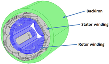
Figure 20. An example of a fully superconducting machine configuration. © 2013 IEEE. Reprinted, with permission, from [35].
Download figure:
Standard image High-resolution imageThe machine is of a standard radial flux type with distributed saddle windings on the stator. A back iron is used to return the flux and is maintained at ambient temperature outside the cryostat. The cryostat is in vacuum, and the flow of coolant, assumed to be liquid hydrogen (LH2), is contained in tubes. The field winding is comprised of racetrack coils with tape conductors. The rotor is composed of metal components, but part of the shaft is composed of a composite material to thermally insulate the parts at the cryogenic rotor from the rest of the drive train.
The stator winding consists of different phase coils distributed on different radii to allow for the conductors to be mechanically stabilized along their whole length, as shown in figure 21. The number of turns in each phase is modified to obtain a balanced system of inductance and flux linkage between the stator and rotor, therefore minimizing the torque ripple during operation. This stator configuration builds on past work with LTS windings [90].
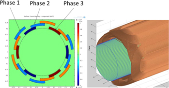
Figure 21. Stator winding configuration of a fully superconducting machine. © 2013 IEEE. Reprinted, with permission, from [35].
Download figure:
Standard image High-resolution imageThe superconducting motors and generators required for turboelectric propulsion rotate at high speeds, in the 4000 rpm to 8000 rpm range, and therefore operate at frequencies of hundreds of Hertz. In order to minimize weight, these machines are invariably of the 'air-core' type, with the armature winding fully exposed to the air-gap flux. Given the resulting high dB/dts, the ac losses in the superconducting armature winding could be substantial using commercially available conductors. Additional challenges include the need for non-conducting cryostats on the stator for many of the configurations considered. If sufficient cooling is available, for example, from on-board LH2 stored for use as fuel in a turbine, the superconducting stators may still make sense for some missions. Multi-filamentary MgB2 conductors with strands less than 10 micrometers, 2G-HTS cables (Roebel or CORC, best with twisted filaments), or other equivalent conductors, could be technology enablers.
Using an AFRL rotor supplied by the Robinson Research Institute, Victoria University of Wellington in New Zealand, a 2 MW fully superconducting machine was sized using a Gramme Ring stator. The following assumptions were made for the rotor: (1) outside diameter = 280 mm; (2) number of poles = 4; (3) rotating speed = 15 000 rpm; (4) nominal field at the rotor surface = 0.54 T; and (5) clear air-gap between rotor and stator cryostat = 5 mm.
With these assumptions, the stator winding was sized to generate 2 MW power using the four commonly available, but very different, superconductor architectures listed below. The ReBCO Ic values were supplied by the University of Houston (UH). The MgB2 data are for a tape measured by Robinson and supplied by Columbus Superconductors SpA.
- (a)Roebel cable employing UH ReBCOReBCO Ic = 2566 A cm−1 at 50 KWidth of individual strand = 2 mm Number of strands = 10 Strand striations = 5
- (b)CORC cable employing UH ReBCOReBCO Ic = 2566 A cm−1 at 50 K Width of individual strand = 2.5 mm Number of tapes = 10 Former diameter = 4 mm
- (c)Twisted tape stacks of UH ReBCOReBCO Ic = 2566 A cm−1 at 50 KWidth of individual strand = 2.5 mm Number of tapes = 8 Diameter of tape bundle = 2.7 mm
- (d)MgB2 tape stacks—fully decoupled filaments
Wire Ic = 800 A at 24 K
Number of tapes = 3
Stack Ic = 2400 A
Tape width = 3 mm
Tape thickness = 0.7 mm
Number of filaments = 19
The Gramme ring stator's inside and outside layers are located at radii of 165 mm and 220 mm, respectively. An electromagnetic shield (EM) of 5 mm thickness is located at a radius of 275 mm. Stator windings operate at 50 K with the exception of the MgB2 that operates at 24 K.
The total ac stator-winding losses, estimated by combining the Brandt (magnetization) and Norris (transport) losses where strands in the cables are assumed to be uncoupled, i.e. infinite inter-strand resistance and therefore all calculated coupling losses are zero. This simple calculation for the four options noted above (a, b, c, and d), are determined to be 1.7 kW, 10.4 kW, 10.0 kW, and 0.69 kW, respectively. After combining non-superconducting losses and the cryogenic temperature losses, the overall efficiencies are estimated to be 96.2%, 87.2%, 87.4%, and 95.3%, respectively. The highest efficiency is achieved with a ReBCO Roebel cable winding followed by a multi-filamentary MgB2 tape winding. However, it should be noted that the I(operating)/Ic ratio for the ReBCO windings is ∼19% as compared to ∼40% for the MgB2 winding. Thus the MgB2 winding has a much smaller margin for accommodating fault currents. Moreover, there is a three to four times smaller cooling penalty for operation at 50 K as compared to 24 K [36].
Although higher excitation fields can be employed in the stator winding region, there will be an accompanying higher ac loss leading to lower overall efficiency.
Concluding remarks
Implementing fully superconducting machines requires developing a cost-effective, highly efficient (low ac-loss, high-operating temperature) conductor. A number of topologies have been explored, but all rely on conductor development. The calculations described above demonstrate that a significant reduction in ac loss can be achieved by using specialty low-loss superconductors.
4. Super permanent magnetic (PM) machines
Mitsuru Izumi
Tokyo University of Marine Science and Technology
Status
Bulk HTS superconductors show great magnetic flux-trapping performance as cryo-PMs [37–39]. This capability is associated with their high critical current density, Jc, and has a very strong HTS diamagnetic response. The trapped flux is more than an order of magnitude higher than conventional Fe-Nd-B magnets. However, because of a short coherence length and large anisotropy, high-angle grain boundaries may lead to weak links and reduce the critical current. For engineering applications, high-textured and homogeneous single grains/domains are required. Thanks to the improvements in processing technology, large-dimension, high-performance REBa2Cu3O7-z (RE-Ba-Cu-O, RE: rare earth element and Y), single grains have become available. The trapped magnetic flux density (Bt), produced by flux-pinning or induced superconducting currents flowing persistently in an RE-Ba-Cu-O grain, can be expressed as Bt = Aμ0Jcr, where A is a geometrical constant, μ0 is the permeability of a vacuum, and r is the radius of the grain. The basic issue for enlarging the bulk size is maintaining a continuous textured growth from the view of crystallization technology [40, 41].
Current and future challenges
An effective magnetization technique for HTS bulks cooled below the superconducting transition temperature Tc is a key to realizing a high magnetic flux density suitable for a field-pole application with an electric motor or generator. The static magnetization process under cooling—field-cooled magnetization (FCM)—of the HTS bulk was qualitatively based on a conventional critical model (Bean's model). For practical applications, the pulsed field magnetization (PFM) after cooling below Tc was developed to attain the advantages of compactness and mobile convenience [42]. The in situ PFM enables us to magnetize the bulk assembled in a variety of machine applications. However, PFM results in a trapped magnetic field that is lower than the trapped field obtained by FCM. The solution considered for this problem is to eliminate the local heat generation associated with transient flux motion during the course of PFM.
Multiple pulse-magnetizing in PFM leads to an improvement in the trapped magnetic field property [42–45]. It can acquire a trapped high-magnetic flux density—an integrated magnetic flux with a conically shaped trapped flux density distribution as observed in FCM [37–41]. Hence, the HTS bulk is cooled after the pulsed field is applied repeatedly. The cooling temperature for each magnetization must be controlled to obtain a desired trapped magnetic field. Because the multi-pole motor must first go through the PFM process steps before start-up, it takes considerable time for the PFM procedure to become ready for driving electric machines. This process should require very little time in order to be practical in electric machine applications. Compact equipment, mobile convenience, and rapid magnetization are still advantages of PFM [42, 44]. Large field leaps have been reported [45] based on inhomogeneous melt-growth morphology and complex behaviour of flux during PFM, and encourage us to obtain full magnetization with a flux jump in the bulks where the Bean model is not applicable [46]. Hence, we are required to achieve precise control of the local heat, associating the motion of magnetic flux penetrated by the rapid rise time of the pulsed magnetic field. This results in the decrease of local Jc with increasing temperature in the bulks. Thus, the flux-trapping performance should be improved by suppressing local heat generation during PFM [47].
In PFM, the discharge current to a pulsed copper armature coil gradually decreases due to self-induction if the electric discharge is interrupted while an electric charge remains stored in the capacitor [47]. The magnitude of the magnetization waveform is controlled for the active discharge interruption from the capacitor [48]. It can suppress local heat generation by decreasing magnetic flux motion to limit the rate of rise in magnetic flux density per unit time. Thus, single-pulse magnetization increases trapped magnetic flux with the pulsed magnetic field using a suitable waveform as a function of time to minimize the magnetic flux motion [48]. The present waveform-controlled WCPM actively controls the magnitude of the pulse discharge, improving the trapped magnetic field property (see figure 22).
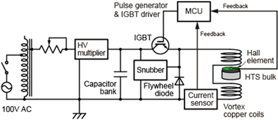
Figure 22. Schematic of pulse magnetization equipment with feedback circuit. Reproduced from [46]. © IOP Publishing Ltd. All rights reserved.
Download figure:
Standard image High-resolution imageActive control requires inputting magnetic flux-state information to penetrate the bulk. Although it is difficult to measure the local transient heat directly generated by this penetration, the transient magnetic flux density can be measured using a Hall element placed at the centre of the top surface of the bulk field pole. Controlling to minimize the flux motion enables us to trap the magnetic flux with the maximum. Employing a suitable rise time and about four seconds of pulsed field duration, the HTS bulk traps a high magnetic flux density by single PFM with a waveform control made from active feedback of the Hall sensor voltage as a function of time (figure 22). During a single PFM application, the maximum trapped magnetic flux density exceeds 90% of the trapped field density obtained by FCM at liquid nitrogen temperature [48, 49].
Advances in science and technology to meet challenges
Applied bulk superconductivity to electric machines attracts much attention because of high magnetic flux trapped by the relevant magnetization process [37–39]. The main goal is to develop a high-power-density motor/generator aimed for use in a rotating machine [44, 49, 50]. It would be superior to synchronous machines with conventional permanent magnets. The R&D targets vary widely—from materials, electro-magnetism, and combined cryogenics to mechanical design. A bulk-material magnetization process for a higher trapped flux is essential to provide homogeneity of flux distribution after magnetization and leads to a higher integrated flux. The requirement is to produce at least a 3 T trapped magnetic flux density and thus create stronger magnets. This would lead to high torque/power and a compact design.
Another key target is the design of on-board magnetization. To reach the desired torque while keeping a compact design, a consequent amount of magnetic flux must be trapped in the HTS bulk-material magnets (the 'bulks,' super PM). It is also necessary to develop an optimized design of the compact on-board magnetization copper coil. The armature windings are able to play the role of magnetization coils [51, 52]. The on-board field-pole magnetization system relies not only on the copper coil but also on its cooling device and the cryocooler system during operation [44]. Good comprehension of the HTS bulks leads to more efficient cooling while reducing the machine size. When working with HTS bulks whose Tc is above 90 K, additional temperature reduction improves the control of heat loss as thermal conductivity and heat capacity are also functions of temperature.
The design and manufacture of the armature/magnetization coil must meet the requirements of field-pole bulks and the concept design of the rotor-armature structure [50, 51]. The assembly and construction of the complete system, for example, a >10 kVA- HTS bulk generator prototype, along with test results, would be near-future milestones. Until now, both radial and axial-flux machines have been demonstrated and/or proposed [50, 121–123, 140, 141].
An axial-gap type synchronous rotating machine, composed of a flux rotor with eight GdBCO HTS bulk magnets as a field pole, was designed and constructed [52]. A series of tests on the single rotor-type HTS synchronous motors have been reported, as shown in figure 23 [53]. The design and construction of the single rotor-type HTS synchronous motor has been reported [53–55]. The bulk magnets, acting as field poles, are magnetized by copper armature coils excited with a pulsed current. The split-type copper armature coil pairs of concentrating winding were developed as a vortex type for the first time [52]. In contrast to the coil of HTS tape winding of 1G and/or 2G wires, an active control of the magnetic flux generation by dc pulsed current control can be accomplished by applying complementary magnetization or demagnetization.
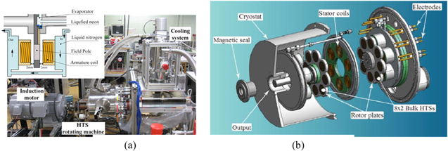
Figure 23. (a) Axial-gap HTS synchronous generator with single-rotor [53] and (b) Axial-gap HTS [54] synchronous motor with twin-rotor. Reproduced from [53]. © IOP Publishing Ltd. All rights reserved.
Download figure:
Standard image High-resolution imageHence, we need to study a survivability qualification of the trapped flux as well as flux density distribution on each bulk under the rotation with and without load in the applied axial-flux synchronous machine. Early developed single-rotor motors have been upgraded to a twinned rotor type in which we have employed a couple of flux rotors with eight bulks, i.e. 16 bulks as shown in figure 23(b) [54]. The characteristics of the twinned rotor motor, as well as trapped flux density, have been investigated as a function of time under a long synchronous operation.
In a super PM, a magnetized HTS bulk, macroscopic electric currents create magnetic flux, and the flux density distribution and demagnetization properties differ from those of conventional permanent magnet alloys. Within an electrical machine, the magnetized HTS bulk will be exposed to external fields which may change in both angle and magnitude as a function of time when the machine is operated [141]. There are cyclic effects that can degrade the trapped fields [142, 143]. A situation where the superconductor experiences a magnetic field with a transverse component may occur several times during the operation of the machine [142, 144]. Additional use of ferromagnetic materials has been proposed together with bulk HTS in order to enhance the trapped magnetic field, and this hybrid structure protects against the transverse magnetic field [144]. There are anisotropic effects associated with the application of magnetic fields transverse to the magnetization, although these effects may be minimized by reducing the operating temperature below the magnetizing temperature [141].
The practical effectiveness of employing 2G superconducting stacked tapes [145] is another way to obtain trapped flux in electric machinery through a magnetization process similar to that with HTS bulk. While it has been claimed that demagnetization from the crossed field may affect the trapped flux in machines, Baghdadi et al [146, 147] employed the superconducting stacked tapes as a field pole in a synchronous superconducting motor and studied demagnetization due to crossed field effects on this new type of super PM field-pole composed of 2G stacked tapes. Applying the transverse AC field in the a-b plane, the effects of frequency, amplitude, and number of cycles of the transverse magnetic field have been reported [142]. The demagnetization up to 10% was found in contrast to 50% in the case of the bulk with the former reports at 77 K. A stack of 2G superconducting tapes has been examined by the finite element method model and the consequences of applying the crossed magnetic field on the sample have been studied [143]. Such 2G-HTS tape stacks have the potential to form a field pole leading to high-power density machines.
Concluding remarks
In prior magnetizations, bulks were assembled in the machine as field poles on the rotor [48], necessitating the magnetization of the bulks after zero-field cooling. Now it is possible to magnetize the bulk cooled below Tc by the momentary application of a large field, e.g. twice that of the target magnetic field [45–48]. An axial-flux synchronous motor was developed as a prototype by using Gd-Ba-Cu-O family bulks as field poles [52–54]. It is highly probable that off-axis magnetization for bulk field poles can be included by applying the magnetizing pulsed field along an angle with respect to the c-axis, rather than along the c-axis of the bulk HTS of ReBCO. This may contribute to the enhancement of electric and/or magnetic machine design for the better performance of rotating machines [56]. A key feature is the superior torque/field pole flux compared to conventional PM machines. For the cooling procedure, thermosyphon of Ne has been applied and tested to enhance and control useful field strength [53].
HTS synchronous machines, as well as linear motor/generator systems, are expected to become indispensable in the next decade. In large torque/output power applications, such as wind/ocean renewable energy generators and ship/aeronautic propulsion motors, these machines are highly desirable because they have the potential to provide high energy density per weight/volume. The materials' performance has not yet made satisfactory progress, and the operating temperatures to fulfil specifications are close to 30 K or lower. Cryogen resources, among them helium, hydrogen and neon, are employed in the HTS machine's appropriate cooling system. The challenges of applying superconducting bulks to practical rotating machines and scaling up to larger ratings continue to be studied. The ability to perform on-board magnetization is required in practical applications. The use of armature windings or additional copper windings to magnetize the superconducting bulks up to sufficient magnetic flux to serve as the field poles is being explored. 2G-HTS tape stacks are a promising alternative to HTS bulks for use in field poles leading to high-power density machines. More experimental work on bulk superconducting machine prototypes, at scale, is required to assess the merits and demerits for the application of superconducting PMs to rotating machines as compared to winding-type rotors.
5. Advanced conductors
Rod Badcock1, Bob Buckley1, David Loder2 and Tabea Arndt3
1Victoria University of Wellington
2University of Illinois, Urbana-Champaign
3Siemens Corporate Technology
Status, current and future challenges
The availability of cost-effective high-performance superconducting wire is critical to the widespread adoption of superconducting machines. Projecting the future performance of HTS wire has its challenges. However, based on the performance of champion samples and the time required for these results to appear in manufactured products gives us some guidance. Below we have listed the Ic results, as a function of temperature and field, that we have measured in our laboratory, along with results from other researchers, as a basis for estimating what advances in Ic we might expect in the near future.
All Ic values are determined at a standard voltage of 1 μV per cm. Note that the data in table 5 should be treated with caution, as explained below.
- We have reported the critical current-per-width for an applied field perpendicular to the wide face of the tape. In fact, it is well known that this is not always the minimum in Ic. The minimum, in most cases, determines the machine operating conditions.
- Different manufacturers have optimized for various operating temperatures and fields. We report on wire data suitable for rotating machines, e.g. AMSC has two products and we report data on only their 'coil wire' that has been optimized for low-temperature high-field operation, likewise Superpower with their Advanced Pinning wire. These wires tend to do relatively less well at 77 K.
- It should also be noted that the data above are representative of the best results we have obtained and not a statistically robust analysis of any one manufacturer's production wire.
- Table 5 is put together not to compare wire from different manufacturers, which is generally continually improving, but to develop a reasonable plot of where the performance of HTS wire may take the community in the medium-term future. Currently available production wire performance at 30 K and 3 T (March 2016):
- Ic of ∼300 A cm−1 width is widely available from all manufacturers listed above.
- Ic of ∼550 A cm−1 width is currently available from a number of manufacturers, e.g., AMSC, Superpower, STI.
- Current state-of-the-art in long-length production wire is 1000 A cm−1 width and is available from Fujikura Development wires at 30 K and 3 T.
- 1000–200 A cm−1 have been measured on development samples from AMSC and STI.
- R&D samples on technical substrates that have produced values as high as 3300 A cm−1 width have been reported [60].Given the gap between experimental wire performance and current production wire, and the observation of how quickly lab-based performance gets into manufacturing, it would be reasonable to anticipate a projected improvement in Ic over the next five years of a factor of two to three. This large improvement in Ic will have benefits through:
- Raising the feasible operating temperature, thereby reducing the power requirements and size of the cryocooler. For example, if 300 A cm−1 width is required to operate at 3 T for a particular design, then this can be achieved at 30 K with commonly available wires today, or at 50–60 K with the performance achieved by development wires, or at 70 K with the performance achieved in R&D champion samples projected onto production wires. Lifting operating temperatures to 50 K is likely in the next three to five years.
- Reducing the quantity of wire required, thus reducing the size and weight of the coils
- Reducing or eliminating the required iron yoke
- Reducing the machine cost.
Table 5. Review of HTS wire performance.
| Ic/width (A/cm-width) | ||||||
|---|---|---|---|---|---|---|
| Wire type | Reference | Field perpendicular to tape face | ||||
| Production wires | 77 K 0 T | 65 K 3 T | 50 K 3 T | 30 K 3 T | ||
| AMSC | Production coil wire | Robinson data [57] | 350 | 100 | 240 | 450 |
| AMSC | Production coil wire | Fleshler et al (2014) [58] | 370 | 560 | ||
| Fujikura | Production wire | Robinson data [57] | 510 | 190 | 500 | 1000 |
| STI | Production wire | Robinson data [57] | 450 | 130 | 380 | 870 |
| SuNAM | Production wire | Robinson data [57] | 540 | 65 | 150 | 300 |
| SuperOx | Production wire | Robinson data [57] | 380 | 90 | 200 | 400 |
| Superpower | Production advanced pinning wire | Robinson data [57] | 250 | 100 | 300 | 550 |
| Theva | Production wire | Robinson data [57] | 400 | 140 | 320 | 660 |
| Sumitomo | Production - new type H 1G | Robinson data [57] | 440 | 0 | 30 | 540 |
| Development wires | ||||||
| AMSC | Development wire | M Rupich et al (2016) [59] | 240 | 120 | 320 | 1020 |
| STI | Development wire | Robinson data, (unpublished) | 750 | 190 | 550 | 1200 |
| R&D samples on technical substrates | ||||||
| U. Houston | R&D sample wire | Selvamanickam et al [59, 60] | 650 | 670 | 1570 | 3300 |
Advances in science and technology to meet the challenges
One path to increased power density is the development of higher performance superconductors. Low-temperature superconductors such as Nb3Sn remain the conductors of choice in applications such as high-energy physics due to their capability for large critical currents even at high fields. The large magnetomotive force (MMF) potential of these conductors allows for air-gap fields higher than 3 T, even in completely air-core electric machines; however, the difficulty comes with the cost and weight of the cryogenic systems for LTS conductors [61].
Recent advances in HTS conductors through Zr-doping and enhanced flux-pinning techniques have brought high-field critical currents in YBCO tapes closer to parity with high-performance LTS [62]. One recently developed research strand has achieved 4000 A critical current at 3 T, 30 K through increasing the tape substrate thickness [60]. With such conductors, similarly high air-gap fields are attainable, while eliminating the majority of the cryogenic system weight by operating near 30 K instead of 4 K.
To give an example of the potential effect on weight reduction, a completely air-core, high-field design is considered which is projected to achieve 40 kW kg−1 at 8000 rpm employing composite structural materials. If the high-field Nb3Sn windings are replaced with YBCO at 30 K, cryocooler weight can be reduced from 120 kg to 10 kg [133, 137]. The order of magnitude weight reduction in the cooling system corresponds to a projected increase from 40 kW kg−1 to 54 kW kg−1 (35% increase) [138].
The application in rotating electrical machines puts many challenges to superconducting windings and to wires. One has to consider several root causes for stresses on windings and wires:
- High centrifugal forces due to radial distance to central axis of rotation. This distance in the rotor is, by purpose, very large in order to get the rotating windings as near to the stator as possible.
- High Lorentz forces, especially under fault conditions (these might be even higher than the centrifugal forces).
- Strains and shear stress originating from dynamic cool-down (temporary mismatch of coefficients of thermal expansion of the different components—even in the wire itself).
These mechanical loads have both longitudinal components, which could be taken as tensile stress on the wires, and in most cases, a transverse and/or a shear-stress component.
When switching from 1G-HTS (ceramic filaments in matrix of moderate strength and perhaps with an outer high-strength sheath) to 2G-HTS (layered structure with ceramic thin films), stress distribution inside the wire and the tolerance of this might change considerably. Consequently, several groups reported on the failure of 2G-HTS coils of considerable winding height [63–65] and some 2G-HTS suppliers started to elaborate on workarounds, wire architecture, and manufacturing processes to improve these aspects of mechanical strengths and tolerances. The stress situation in a specific coil geometry combining materials of former (e.g. steel, copper, plastic), resin, insulation, co-wound shunt (copper) and the layers of the tape of the specific supplier itself will be very complex and there is no unique description available. Nevertheless, as tensile strength usually is a well known property with high load tolerance, a first approach to check the eligibility of a selected tape to be used in coils for rotating machines is by characterizing the tape by its transverse stress tolerance.
A good means for checking the transverse stress tolerances (and to some extent the shear stress tolerances) is the measurement of transverse critical stress. Figure 24 shows a very simple setup to measure the transverse critical stress with a two-stud method while having a measurement of the critical current at the same time (most suitable when immersed into liquid nitrogen).

Figure 24. Principle setup of a mimic to measure transverse critical stress and critical current of a 2G-HTS at the same time. Massive current leads (wire ends) and voltage taps (near studs) can be seen. It is crucial that the studs will not create shear stress in the wire when pulling apart. Reproduced with permission from [66].
Download figure:
Standard image High-resolution imageFrom an experimental point of view, it is important to ensure a strong and homogenous contact of the studs to the wire surface while at the same time ensuring a well-defined cross section to create homogenous stress and not degrading the wire by creating local overloads as an artefact from the preparation process. These measurements can be used as a tool to create data for a Weibull plot. Figures 25 and 26 show such Weibull plots and the corresponding mathematical fits to the data.
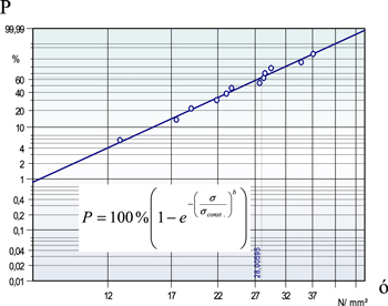
Figure 25. Weibull plot from the measurement of transverse critical stress. The probability for failure P vs applied stress σ shows in a two-parameter fit a non-vanishing probability even for very small/vanishing stresses. Reproduced with permission from [67].
Download figure:
Standard image High-resolution image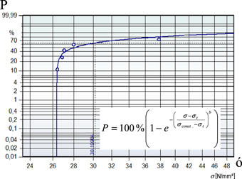
Figure 26. Weibull plot from the measurement of transverse critical stress. The probability for failure P vs applied stress σ shows in a three-parameter fit a threshold value of σt ≈ 26.4 N mm−2. When applying smaller transverse stresses, the failure probability vanishes [67]. © IEEE. Reprinted, with permission, from [26].
Download figure:
Standard image High-resolution imageComparing both figures, it becomes clear that only the 2G-HTS wire of figure 26 is suitable to be used in large windings of rotating machines. Additionally, it would be better to have even higher values of the threshold transverse stress, as this (with the addition of a safety margin) will enter directly into the design process of the windings and the machine. Recently, some 2G-HTS suppliers successfully addressed these issues, but extensive test series in advance of machine construction would be mandatory to have a secure base for long-term operation of rotating machines. Considering cycling of transverse loads, up to now, there is no evidence for degradation, as long as the transverse stress is well below the threshold σt [66]. There might be the need to recheck this for specific applications.
Concluding remarks
Superconducting wire meeting both the required electrical and magnetic performance at practical temperatures (20–30 K) and the mechanical performance criteria is currently available. Laboratory investigations indicate that the community can expect to see these improvements embedded in commercial wire within the next three to five years. An increase, however, in all these properties, along with the availability of cost-effective wire, will be critical for widespread adoption and the development of cost-effective rotating machines.
6. Advances in cryocooling
Timothy Haugan1 and Ernst Wolfgang Stautner2
1US Air Force Research Laboratory
2GE Global Research
Status
The use of superconductive/cryogenic components in motors/generators requires technologies to cool them to cryogenic operational temperatures. This can be achieved with individual or a combination of traditional methods including cryocoolers, cryogenic liquids, and solids cooled below melting points, such as frozen carbon dioxide (dry ice) at <194.5 K and frozen nitrogen cooled below the melting point of 77 K down to 20 K–50 K. Frozen nitrogen cooled to 44 K is used on the Hubble Space Telescope to keep cryogenic components such as detectors cooled for up to ten years without replenishing.
Current and future challenges
To achieve cryocooling, a cooling source is necessary in addition to ancillary technologies such as cryogenic shielding, vacuum technologies, thermal engineering and control, sensors, and others. This subtopic review will not cover all these technologies. It will focus only on the cooling sources and, specifically, on cryocoolers and liquid cryogens.
Cryocoolers are a well-established and mature technology up to TRL 9 with actual systems proven through successful mission operations for a wide range of cooling powers from 10−2 W to 106 W and varying machine types and thermodynamic cooling cycles. Comprehensive review articles describe cryocooler properties including cooling performance, mass and size, cost, and lifetime and reliability [68–71]. Over 30–40 years, cryocoolers have not reduced much in size. Other properties, such as lifetime, have increased by more than an order of magnitude to five to ten years for Stirling cycle machines, and efficiencies at 80 K have increased up to five times [68]. In the years since 2000, large improvements have been obtained for Brayton-cycle machines. These are considered the best option for aircraft application from 20 K–110 K operation for multiple reasons, at least for high cooling powers >100 Watts. For air and space applications, both Brayton and Stirling machines have met additional requirements including robustness in extreme stressing environments, such as rocket launch and force transients up to 12 G, abilities to work in different orientations, ultra-high reliabilities >99.99% for mission-sensitive applications, electromagnetic interference, and logistics considerations, such as ease of use [70]. The requirement for highest power densities is especially important for air and space platforms and can become a deciding criterion if other factors such as coefficient-of-performance are not very different.
Table 6 provides an updated survey of state-of-art cryocoolers that are commercial off-the-shelf products available in 2016, except for select Turbo-Brayton machines. The machines shown in tables 6 and 7 are a sampling of those available that could provide reasonably high power density and efficiency for large magnetic coils of motors/generators, or magnetic resonance imaging, e.g. 1.5 W cooling for the winding wires and magnetic coils and 40–50 W cooling for support structures such as current leads and outer-jacket heat shields. The variety of cryocooler options to choose from is large; typically, one manufacturer will provide 10–20 options for one machine type, optimized for performance at varying temperatures and cooling loads.
Table 6. Survey of state-of-the-art cryocoolers.
| Pinput | Mass | Specific mass | Pout | Pout | Pout | Pout | Costa | MTBF | ||||
|---|---|---|---|---|---|---|---|---|---|---|---|---|
| Machine type | Company | Model | (kW) | (kg) | (kg/kW-input) | at 4.2 K (W) | at 20 K (W) | at 50 K (W) | at 77 K (W) | ($) | (hr) | Reference |
| Stirling 1-Cycle | Cryo-tel | GT | 0.24 | 3.1 | 12.9 | 5.5 | 16 | 200 000 | sunpowerinc.com | |||
| Cryo-tel | CT | 0.16 | 3.1 | 19.4 | 3.5 | 11 | 200 000 | sunpowerinc.com | ||||
| Cryo-tel | MT | 0.08 | 2.1 | 26.3 | 1.2 | 5.2 | sunpowerinc.com | |||||
| STI Conductus | 0.135 | 2.8 | 20.7 | 9 | >1000 000 | www.suptech.com | ||||||
| Stirling 2-Cycle | Stirling Cryo & Refrigeration (SCR) | SPC-1 | 12.6 | 551.0 | 43.7 | 450 | stirlingcryogenics.com | |||||
| SCR | SPC-4 | 54 | 1150.0 | 21.3 | 1800 | stirlingcryogenics.com | ||||||
| SCR | SPC-1T | 11 | 551.0 | 50.1 | 75 | $80 K | stirlingcryogenics.com | |||||
| SCR | SPC-4T | 45 | 1160.0 | 25.8 | 300 | $160 K | stirlingcryogenics.com | |||||
| Thermoacoustic Stirling | Chart/Qdrive | 2s102K | 0.25 | 15 | 60 | 8 | 125 000+ | chartindustries.com | ||||
| Chart/Qdrive | 2s132K | 0.6 | 23 | 38 | 25 | 125 000+ | chartindustries.com | |||||
| Chart/Qdrive | 2s226K | 2.75 | 80 | 29 | 140 | 125 000+ | chartindustries.com | |||||
| Chart/Qdrive | 2s241K | 4.5 | 115 | 26 | 175 | 125 000+ | chartindustries.com | |||||
| Chart/Qdrive | 2s362K | 20 | 388 | 19 | 1000 | 125 000+ | chartindustries.com | |||||
| Brayton | Aerospace | 0.16 | 11.0 | 68.7 | 3.5 | 9.8 | F. Berg et al [65], J. Palmer et al [66] | |||||
| Industrial | 0.2 | 15.5 | 77.5 | 4.4 | 12.3 | [65, 66] | ||||||
| Aerospace | 0.25 | 10.5 | 42.0 | 5.5 | 15.4 | [65, 66] | ||||||
| Aerospace | 0.4 | 20.8 | 52.0 | 8.8 | 24.6 | [65, 66] | ||||||
| Aerospace | 3 | 21.0 | 7.0 | 65.7 | 184.4 | [65, 66] | ||||||
| Aerospace | 20.8 | 249.6 | 12.0 | 455.5 | 1278.7 | [65, 66] | ||||||
| Industrial | 1000 | 8000.0 | 8.0 | 21 897.8 | 61 475.4 | [65, 66] | ||||||
| Creare | 10 | 30 | 3 | 219.0 | 614.8 | J. Felder et al [64] | ||||||
| Creare | 32 | 96 | 3 | 700.7 | 1967.2 | [64] | ||||||
| Creare | 160 | 480 | 3 | 3503.6 | 9836.1 | [64] | ||||||
| Taiyo Nippon Sanso | 50 | 2.5 | www.tn-sanso.co.jp/en | |||||||||
| Taiyo Nippon Sanso | 170 | 11.4 | www.tn-sanso.co.jp/en | |||||||||
| Gifford McMahon | ARS | DE-202SE | 3.6 | 80.1 | 22.3 | 0.1 | 2.3 | 4 | www.arscryo.com | |||
| ARS | DE-204SE | 3.6 | 80.1 | 22.3 | 0.2 | 8.0 | 14 | www.arscryo.com | ||||
| ARS | DE-210SE | 7.7 | 128 | 16.6 | 0.8 | 16.0 | 26 | www.arscryo.com | ||||
| ARS | DE-215SE | 6.8 | 121 | 17.8 | 1.5 | 40 | www.arscryo.com | |||||
| SHIcryogenics | SRDK-101D-A11B | 1.5 | 49.2 | 32.8 | 0.1 | 5 | 15 000b | shicryogenics.com | ||||
| SHIcryogenics | RDK-205D | 3.8 | 84 | 22.1 | 0.5 | 4 | 15 000b | shicryogenics.com | ||||
| SHIcryogenics | SRDK-305D-A31C | 3.8 | 111 | 29.2 | 0.4 | 33 | 15 000b | shicryogenics.com | ||||
| SHIcryogenics | SRDK-305D-A31D | 3.8 | 111 | 29.2 | 0.4 | 40 | 15 000b | shicryogenics.com | ||||
| SHIcryogenics | SRDK-408D2-A61C | 7.5 | 178 | 23.7 | 1 | 65 | 15 000b | shicryogenics.com | ||||
| SHIcryogenics | SRDK-415D-A61D | 7.5 | 188.5 | 25.1 | 1.5 | 45 | 15 000b | shicryogenics.com | ||||
| Cryomech | AL125 | 3.3 | 88.2 | 26.7 | 70.0 | 116.4 | 15 000b | www.cryomech.com | ||||
| Cryomech | AL300 | 7 | 130.6 | 18.7 | 200.0 | 310 | $28 K | 15 000b | www.cryomech.com | |||
| Cryomech | AL325 | 10.4 | 212.5 | 20.4 | 63.0 | 227.0 | 279 | 15 000b | www.cryomech.com | |||
| Cryomech | AL330 | 10.4 | 212.5 | 20.4 | 40.0 | 170.0 | 250 | $50 K | 15 000b | www.cryomech.com | ||
| GM Pulse-Tube | Cryomech | PT60 | 2.9 | 76.7 | 26.4 | 28.0 | 57 | $17 K | 25 000b | www.cryomech.com | ||
| Cryomech | PT90 | 4.3 | 118.2 | 27.5 | 48 | 86 | 15 000b | www.cryomech.com | ||||
| Cryomech | PT415 | 9.2 | 215.5 | 23.4 | 1.5 | 15 000b | www.cryomech.com | |||||
Table 7. Cryocooler options for the 40–50 W thermal load of system and shielding components.
| Temp. | Type/Company | Model | Pin-machine max (kW) | Pin-required (kW) | Mass (kg) |
|---|---|---|---|---|---|
| 50 K | GM, SHI Cryogenics | SRDK 415D-A61D | 7.5 | 7.5 for 45 W | 189 |
| 50 K | GM, ARS | DE-215 s | 6.8 | 6.8 for 40 W | 121 |
| 50 K | Brayton | 3 | 0.81 | 21 | |
| 50 K | Stirling, Sunpower | Cryo-tel GT | 2.2 | 2.2 | 27.9 |
| 77 K | Stirling, Sunpower | Cryo-tel GT | 0.96 | 0.8 | 12.4 |
Advances in science and technology to meet challenges
Cryocooler power density, efficiency, and size can all become critical factors affecting system viability. These factors are also referred to generally as the size, weight and power (SWaP) properties. Figures 27 and 28 show the SWaP properties for cryocoolers from tables 6 and 7. Figure 27 plots the inverse of power density of the cryocoolers and shows that there are significant differences in machine design and impact on power densities. In general, as the power levels increase for a given cryocooler type, the power densities also increase, reaching an ultimate limit. For input powers <500 Watts, the Stirling machines provide higher power density than other machines and are optimal. However, for input powers >1 kW, the Brayton-cycle machines are the best option. The dramatic impact of increasing the operation temperature to improve SWaP properties is shown in figure 28 for the specific case of achieving 1.5 W cooling power for cryocoolers from tables 6 and 7.
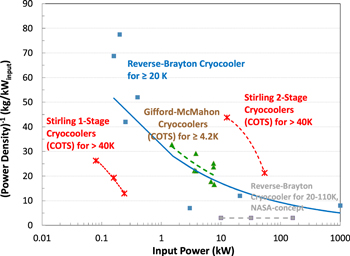
Figure 27. The inverse of power density of cryocoolers from table 6 is plotted for varying input powers.
Download figure:
Standard image High-resolution image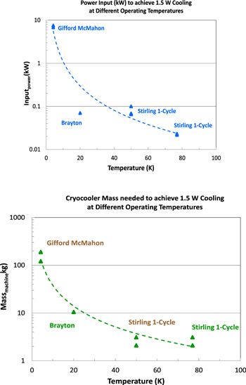
Figure 28. The impact of stator/rotor operation temperature on cryocooler SWaP properties are plotted for varying temperatures, to achieve a specific cooling power of 1.5 W typical needed for magnet windings of MRI scale machines. Table 6 indicates the maximum cooling power at 4.2 K achievable with commercial cryocoolers is 1.5 W. A dramatic reduction of SWaP ∼ 100–500x is achieved by increasing the operation temperature from 5 K to ≥50 K. The input powers can be a % fraction of the machine maximum, however the mass is fixed because of the specific machine choice.
Download figure:
Standard image High-resolution imageA dramatic reduction of SWaP ∼100–500x is obtained by increasing the operation temperature from 5 K to ≥50 K. This demonstrates the strong importance and advantage of improving YBCO wire performance and increasing the operating temperature, as described in the previous section. The impact of the 5 K vs 50 K operation temperature was accurately determined for one machine in the following section; the system weight was reduced almost by half due to reducing the cryocooler mass from 120–180 kg to <3 kg, and the Powerinput (waste heat) was reduced ∼100x from ∼7 kW to 0.07 kW.
The options of cryocoolers to cool system components, such as current leads or heat shields, are shown in table 7. The GM option is for two-stage machines and would only be chosen if the cooling of components at lower temperatures were needed, e.g <20 K. Otherwise, for 50 K, the Brayton and Stirling machines would be optimum. Cryogenic liquid cooling might be an option to consider, as described in the following subsection.
Choosing a cryogenic liquid for rotating machinery
The system performance objectives and in particular the operating field and temperature, thermal mass and size of superconducting machinery are decisive criteria for selecting a suitable cryogen, as shown in table 8. This is mainly of interest if conductive cold mass cooling using a cryocooler may not be feasible, or thermosiphon and bath cooling is found difficult to implement, and remote or distributed thermal mass cooling becomes more efficient. Although liquid helium has been the coolant choice for LTS type conductors for over 35 years—even earlier in the 1950s—hydrogen has been recognized as a highly efficient cooling medium for aluminum and copper electromagnets operated at 20 K. Hydrogen is safely used as a cooling medium for high-temperature gas turbines in the automotive and space industry and was recently found to be suitable for the cooling of superconducting MgB2 windings, in some cases substituting for liquid helium or neon [75].
Table 8. Property table for cryogenic liquids suitable for cooling superconducting rotating machines (compiled from [76] and [77]).
| No. | Property | Unit | He | H2e | Ne | N2 | Ar | O2 | CH4 |
|---|---|---|---|---|---|---|---|---|---|
| 1 | Boiling point (BP) | K | 4.22 | 20.34 | 27.06 | 77.24 | 87.169 | 90.06 | 111.51 |
| 2 | Solidification point | K | 0.95d | 13.958 | 24.56 | 63.15 | 83.80 | 54.37 | 90.69 |
| 3a | Density of liquid (BP) | kg/m3 | 125.01 | 70.72 | 1207.7 | 807.14 | 1397.1 | 1141.8 | 422.59 |
| 4a | Density of gas at 270 K | kg/m3 | 0.178 | 0.179 | 0.899 | 1.249 | 1.7813 | 1.427 | 0.716 |
| 5 | Latent heat of vaporization | kJ/kg | 20.82 | 445.9 | 85.8 | 198.9 | 161.1 | 213.17 | 510.6 |
| 6a | Specific heat of liquid (BP) | kJ/kgK | 5.24 | 9.71 | 1.86 | 2.04 | 1.078 | 1.7 | 3.48 |
| 7a | Specific heat of gas (RT) | kJ/kgK | 5.193 | 14.31 | 1.030 | 1.041 | 0.5215 | 0.919 | 2.236 |
| 8b | Enthalpy diff vapor (BP to RT) | kJ/kg | 1542.7 | 3509.0 | 282.96 | 234.6 | 112.2 | 193.1 | 397.2 |
| 9 | Boil-off rate for 1 W heat load | l/h | 1.38 | 0.114 | 0.0347 | 0.0224 | 0.016 | 0.0147 | 0.0167 |
| 10a | Gas volume in liters at 270 K | lgas/lliquid | 701.5 | 788 | 1343.3 | 646.5 | 784.3 | 800.2 | 590. |
| 11c | Cooling power of 1 W (at BP) | W | 74 | 7.87 | 3.3 | 1.18 | 0.696 | 0.904 | 0.778 |
aat 0.1 MPa, isobar. bRT = room temperature (300 K). cavailable gas cooling power (W) from BP to RT for a 1 W liquid cryogen boil-off. dat 2.5 MPa. enormal hydrogen.
With the arrival of HTS conductors, it seems a generic cryogenic cooling architecture can now be designed by making use of the excellent cooling properties of helium, either stand-alone or combined with a secondary fluid. For example, a forced flow of high-pressure helium vapor (generated by pumps or circulators) as the primary coolant, preferably in a closed-loop tubing arrangement, maintains the temperature of the superconducting cold mass. The return flow of vapor from the cold mass through the transfer line then passes through an efficient heat exchanger attached to a liquid cryogen reservoir (secondary fluid), where the liquid level in the reservoir is maintained by a vapor recondensing cryocooler.
For liquefaction of cold cryogens, e.g. for cold helium vapor, the factor Pe/Pc = 350, whereas for cold nitrogen gas the ratio of Pe/Pc can be as low as 10 (Pe is given as the electric power consumption, with Pc as the cooling power at low temperature).
The liquid in the reservoir can be chosen as per table 8, depending on the choice of superconducting wire and targeted operating conditions. As can be seen from table 8, row 9, the boil-off rates of LN2, LNe, LAr, LO2, and LCH4 are low enough to provide excellent heat sinks that allow the convenient service of sleeved cryocoolers in a liquid reservoir without any machine downtime. Liquid nitrogen is used mainly for thermal mass cool-down and has its place in superconducting machinery as a cost-efficient cooling medium for SC fault current limiters and pumped SC cables. Table 9 gives an indication of how many liters of liquid are required per kg material, depending on whether the enthalpy of the coolant selected can be utilized or not. For steady-state cooling of large masses, however, the real benefit of liquid nitrogen is revealed when the physical properties of liquid nitrogen or a similar cryogen are combined with those of compressed helium gas, as indicated above. The right coolant choice is important for commissioning and servicing the SC machinery and for re-cool, e.g. after a power outage.
Table 9. Cool-down with cryogenic liquids (compiled from [78]).
| Cryogenic coolant | LHe | LH2 | LN2 | LO2 | LHe | LH2 | ||||||
|---|---|---|---|---|---|---|---|---|---|---|---|---|
| Initial temperature in K | 300 | 77 | ||||||||||
| End temperature in K | 4.22 | 20.34 | 77.24 | 90.06 | 4.22 | 20.34 | ||||||
| Quantity of cryogen required to cool metal | kg/kg metal | l/kg metal | kg/kg metal | l/kg metal | kg/kg metal | l/kg metal | kg/kg metal | l/kg metal | kg/kg metal | l/kg metal | kg/kg metal | l/kg metal |
| Utilizing latent heat of vaporization | ||||||||||||
| Aluminum | 7.5 | 60 | 0.39 | 5.5 | 0.81 | 1.00 | 0.75 | 0.656 | 0.4 | 3.2 | 0.018 | 0.255 |
| Stainless steel | 4.2 | 33.6 | 0.2 | 2.83 | 0.43 | 0.533 | 0.40 | 0.350 | 0.18 | 1.44 | 0.086 | 1.202 |
| Copper | 3.9 | 31.2 | 0.175 | 2.474 | 0.37 | 0.458 | 0.33 | 0.289 | 0.27 | 2.16 | 0.012 | 0.17 |
| Utilizing latent heat of vaporization and enthalpy | ||||||||||||
| Aluminum | 0.2 | 1.6 | 0.074 | 1.046 | 0.51 | 0.632 | 0.51 | 0.447 | 0.028 | 0.224 | 0.0097 | 0.137 |
| Stainless steel | 0.1 | 0.8 | 0.038 | 0.537 | 0.27 | 0.335 | 0.28 | 0.245 | 0.013 | 0.104 | 0.0045 | 0.063 |
| Copper | 0.1 | 0.8 | 0.038 | 0.537 | 0.23 | 0.285 | 0.23 | 0.201 | 0.02 | 0.160 | 0.0065 | 0.092 |
Concluding remarks
In summary, cryocooling is a well-established industry with dozens of commercial manufacturers and multiple technology choices that can be optimized for different operating temperatures and system requirements. Because aircraft flights are limited in duration, typically <16 h, we expect the industry will be able to apply potential weight- and energy-saving options, including the use of cryogenic liquids or cooled solids that can be renewed by re-supply on the ground, or regenerated with a ground-based cryocooler. As an example, liquid natural gas is a fuel source already demonstrated for flight. It has a freezing point from 112 K to 91 K depending on the pressure level and can be used to provide free cooling of many cryogenic components, such as power inverters, BSCCO-2223 power transmission cables, thermal shielding, and upper stages of cryocoolers to improve Carnot efficiencies by up to ∼4x.
As discussed, the steady improvement of superconducting wire Je(H, T) performance at temperatures >50 Kelvin being seen for YBCO, will have a significant impact on reducing cryocooler weights and energy losses, both typically >100x. Superconductor wire technology advancements for YBCO and fine filament MgB2 are already dramatically affecting motor/generator system performance, as described in other topic sections.
Clearly, a standardized cooling approach for SC rotating machines needs to evolve for the future, to guide the cryocooling industry toward the targeted SC application and its design parameters (e.g. high efficiency, light weight, high MTBF, etc). A good working example is given by the MRI industry where cooling power and cryocooler size have been matched to the cryogenic environment.
7. Advanced structural materials
David Loder
Rolls-Royce North American Technologies, Inc.—LibertyWorks
Status
The use of superconducting windings creates a unique opportunity for employing advanced structural materials for weight reduction. Conventional rotating machines are mostly constrained to employing magnetic steel in rotor and stator cores in order to minimize the MMF requirement, fulfilling both structural and magnetic requirements. However, an order of magnitude increase in MMF capability achieved with superconducting windings allows flux to be driven through a much higher reluctance. As discussed previously, the configuration of many superconducting machines includes an air-core rotor and non-magnetic teeth on the stator. With such components reduced to a purely structural role, material options can now be expanded to include advanced non-magnetic materials such as fibre-reinforced composites.
Composite materials are generating a high level of interest for cryogenic applications due to their high strength-to-weight ratios and low thermal conductivities. Composites present unique engineering challenges such as increased propensity for fracture; further, most composites are anisotropic, meaning that the material has different strengths depending on the direction of the applied stress [79]. Two important classes of materials include carbon-fibre and glass-fibre-reinforced composites. While carbon-fibre-reinforced composites typically have a higher strength-to-weight ratio, they are electrically conductive. This can preclude them from use in rotating machinery due to difficulty in managing the heat loads generated by induced currents from ac electromagnetic fields, depending on the specific machine configuration.
Current and future challenges
In any superconducting magnet, the cryogenic portions must be structurally connected to the cryostat, the outside of which is exposed to the ambient temperature. Therefore, it is important to minimize the conductive heat transfer through these structural components. This challenge is exacerbated in superconducting machines as the components must now withstand the torque produced by the machine. Conventional solutions have focused on minimizing the connecting thermal conductance using very strong materials such as titanium alloys to allow an increased thermal path length at the expense of increased strain. Glass-fibre composites have an order-of-magnitude lower thermal conductivity (0.29 W/m K) than traditional alloys, but they still achieve strength-to-weight ratios similar to that of titanium [80]. This makes them very attractive for cryogenic applications, allowing for a large reduction in conductive heat load while maintaining similar structural performance.
High-field superconducting magnets also generate high Lorentz forces which are proportional to the square of the magnetic field (∝B2); this necessitates the use of a restraining assembly to maintain the strain of the superconducting strands within acceptable levels, as well as maintain the physical positioning of the magnet assembly. While material performance is less important from a thermal perspective, the low weight of composite materials offers another opportunity to reduce weight in coil formers and connecting components. The tensile strength of glass-fibre composites can be up to 980 MPa with a density of 2000 kg m−3. Compare this to typical numbers for stainless steel (480 MPa and 8030 kg m−3), and the result is approximately an order of magnitude increase in strength-to-weight ratio. Glass-fibre composites can even achieve double the strength-to-weight ratio of titanium alloys [81].
Advances in science and technology to meet challenges
With air-core architectures, steel cryostats now begin to make a significant impact on the total machine weight. An additional use of composite materials can be the vacuum vessel itself. While composites have no problem withstanding the required pressure, the challenge is in their high permeability to gases. Some groups have employed composite-reinforced vacuum vessels with only a thin steel layer to serve as a barrier to gas interchange [82]. Other work has suggested that liners or coatings may be used to achieve the desired permeability, resulting in even further weight reductions [80].
A concept for an air-core superconducting machine is taken to the extreme in [61], wherein an actively shielded architecture is employed to eliminate the need for any passive magnetic components. A stationary cryostat contains superconducting field coils, while the ac-armature windings are placed on the rotor and connected with slip rings. With the saturation limit no longer a concern, very high magnetic loading is possible. Prior work has shown that air-gap flux density >3 T is achievable in practical designs employing mature, high-performance Nb3Sn superconducting windings [83]. This configuration is illustrated in figure 29.
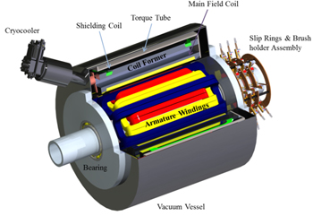
Figure 29. Configuration for actively shielded air-core superconducting machine concept.
Download figure:
Standard image High-resolution imageThe cryogenic cooling system is detailed in figure 30. A two-stage cryocooler provides conduction cooling to achieve the desired operating temperature of the magnets. The first stage is thermally linked to a radiation shield; the majority of the radiation heat load is taken out at the first stage, which maintains the radiation shield somewhere around 40–60 K. A thin, double-turn torque tube is used to increase the thermal path length between the vacuum vessel and the coil former, which is linked to the second stage near 4 K. As such, the conductive heat load from the cryostat is minimized, resulting in reduced cryocooler requirements.
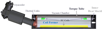
Figure 30. Cryogenic cooling system design concept.
Download figure:
Standard image High-resolution imageConcluding remarks
While the use of composite materials for cryogenic applications involves many complex trade-offs, the added entitlement for power density is enormous. Advanced materials are sure to be an important ingredient in increasing the power density of superconducting machines.
With conventional structural materials (e.g. stainless steel cryostat, titanium alloy torque tube, aluminium coil former), specific power is estimated at 20 kW kg−1 for a 20 MW machine running at 8000 rpm. Of the total 1000 kg, the cryostat (150 kg) makes up a significant portion of total weight (15%). Other structural components such as the coil former (25%) and torque tube (12%) are substantial weight contributions. Taking full advantage of the air-core architecture, the torque tube, coil former, rotor shaft, and cryostat can potentially be constructed with fiber-reinforced composites. This yields a 100% increase in specific power, resulting in 40 kW kg−1. Due to the completely air-core architecture, this design enables a full exploitation of the potential of advanced materials. Although other configurations may result in a smaller improvement, dramatic reductions in weight should be possible even with configurations keeping some magnetic stator or rotor back yokes.
8. System integration and cooling infrastructure
Tabea Arndt
Siemens Corporate Technology, CT REE PEM, Günther-Scharowsky-Str.1, D-91058 Erlangen, Germany
Status
The vast majority of development projects in the field of e-aircraft today focus on key performance metrics of specific devices, e.g. the power density kW/kg. This roadmap document considering large rotating machines (especially in e-aircraft) is based on a 'bottom-up' approach, focusing on the rotating machine, its topologies, designs, etc. What has not been considered are the synergies arising from a systemic view. There are some high-level activities worldwide (e.g. by NASA [1–3], Airbus [128] Euro-CASE [129], ACARE [130], Flightpath 2050 [131]) but these are mostly aiming for reductions of CO2 and NOX emissions and not diving into technical or systemic aspects of the optimised hybrid electric aircraft.
Current and future challenges
The goal of highest efficiency and sustainable e-aircraft will only be reached if synergies resulting from overall thermal design, voltage levels, reduction of device-to-device interfaces, etc are harvested and optimized from a holistic perspective.
Advances in science and technology to meet the challenges
The increasing perception of the importance of a systematic approach can be seen as programs on 'more electric aircrafts' in the USA and Europe have evolved (e.g. in the field of overall thermal design). Furthermore, suppliers of 2G-HTS wires in the USA and Asia have expanded efforts to develop high-performance wires operable at higher temperatures (>30 K, e.g. 77 K) with considerable pinning properties. This enhanced window for operation will enable sophisticated overall designs on a system level.
Figure 31 shows a simplified presentation of ad-hoc relevant aspects and components. Many will interfere with and influence the optimum design and setup of a system.
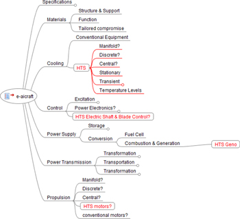
Figure 31. Selected aspects and components for e-aircraft (more than ≈50 passengers).
Download figure:
Standard image High-resolution imageWhen considering specifications which will encompass the mission requirements (flight time, time on ground, maintenance interval, etc), the impact on storage (e.g. fuel and cold) is obvious and will determine the possible cooling technologies. If, for example, liquid hydrogen is chosen as the main fuel, then it might be revealed that the required amount of heat to use in gaseous form will be much higher than the amount of cold power needed by HTS-based equipment. Thus, the cooling comes almost 'for free.' This means not only that cooling technology for HTS equipment is only a small burden on e-aircraft, but that higher cryogenic loss in HTS devices can be tolerated. The latter might open up new options for fully superconducting machines (e.g. more or fewer ac-loss-optimized superconducting wires to be used in the stator). Additionally, using several superconducting devices (e.g. transformers, cables, and rotating machines) at the same or perhaps different temperature levels might enable beneficial synergies in common cooling technology. This might even eliminate the need for dedicated separate cooling technologies.
An overall optimization of the grid within an e-aircraft might yield additional simplicity due to harmonized voltage levels—this will enter directly into the designs of machines and other devices. From this interplay, it becomes clear that the optimum solution cannot be reached by optimizing each single component. In addition, this interplay may result in optimum solutions on device levels, which will not be covered by the design rules, models, and extrapolations used in the other sections. Although this section will reflect the very best of what can be estimated today, these limitations and further potential for optimization should be kept in mind. Finally, to pick one specific example to cover the systemic aspects in more detail, refer to figure 32.
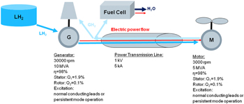
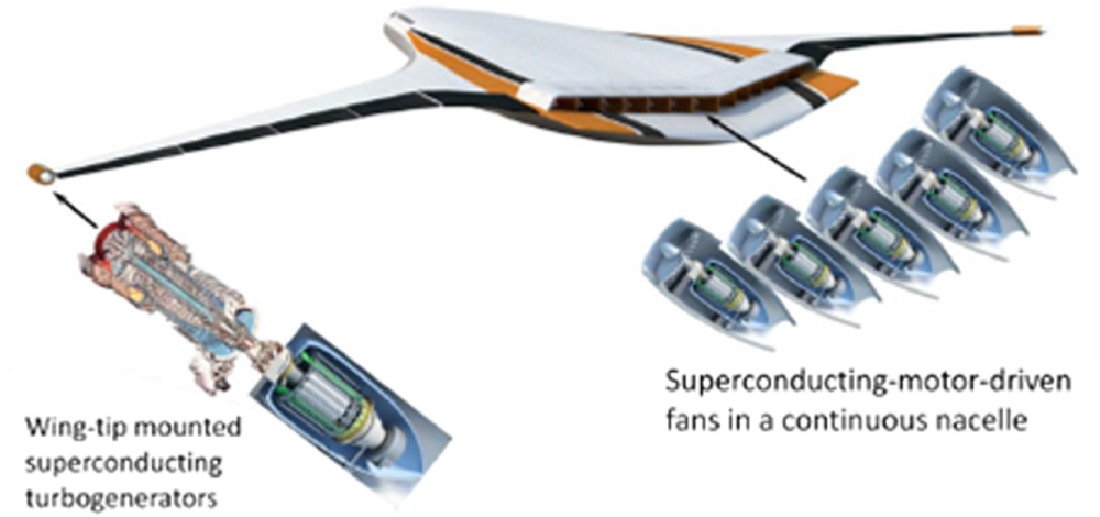
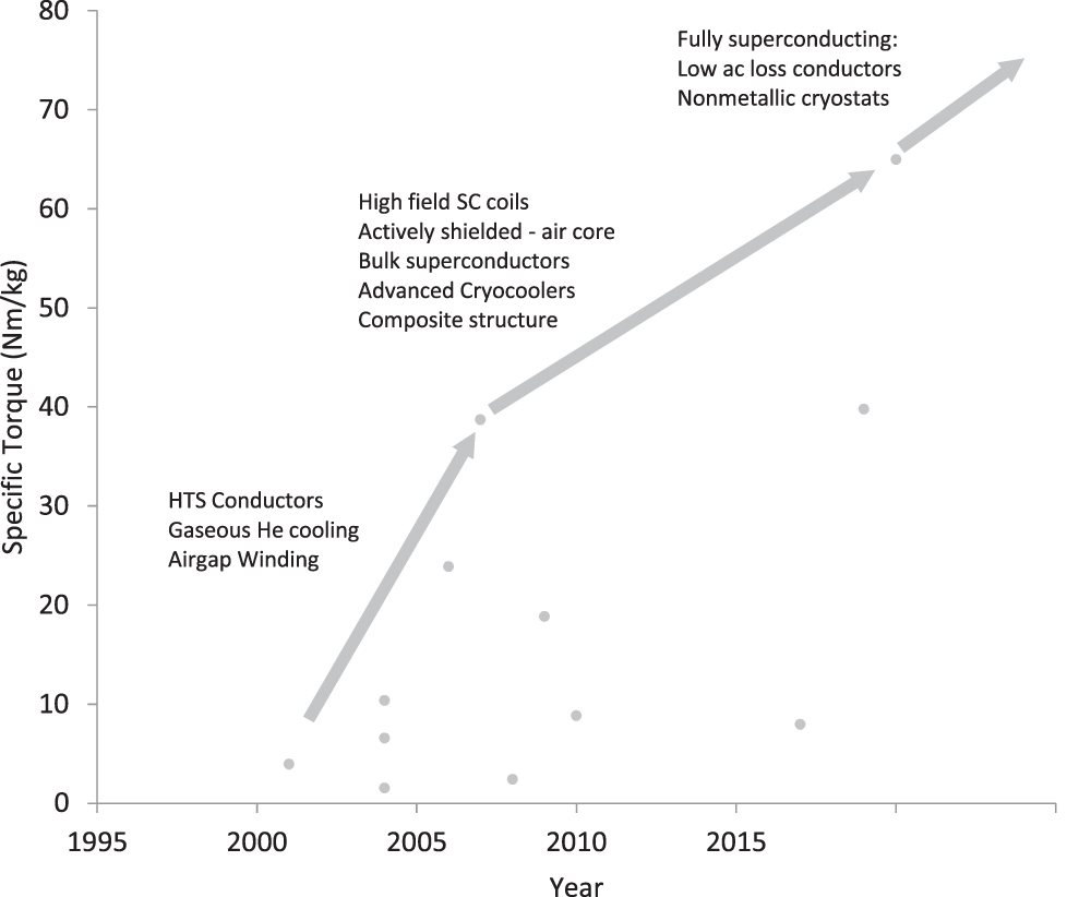
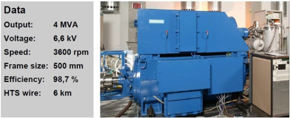
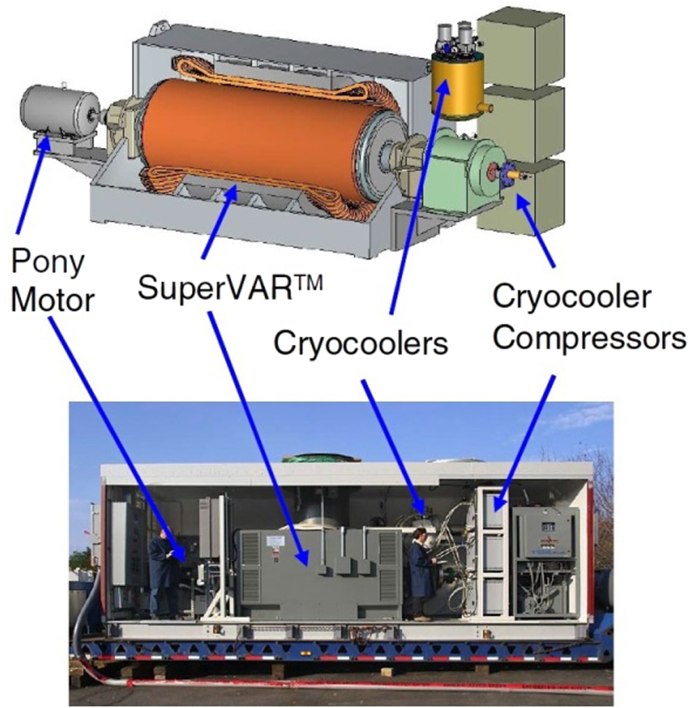
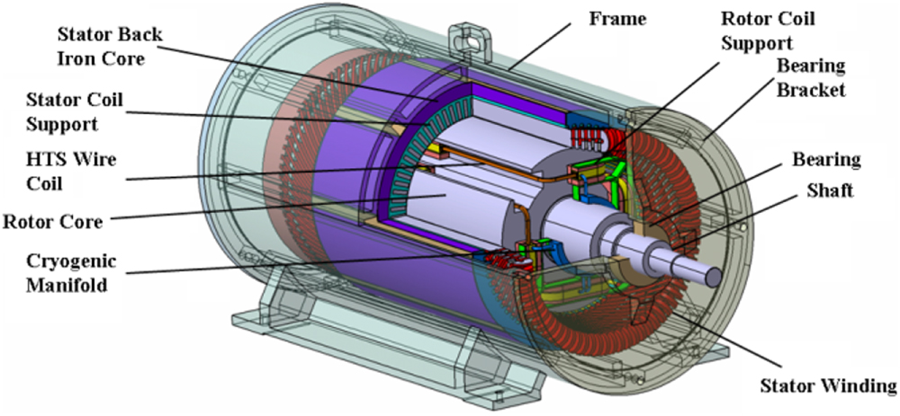
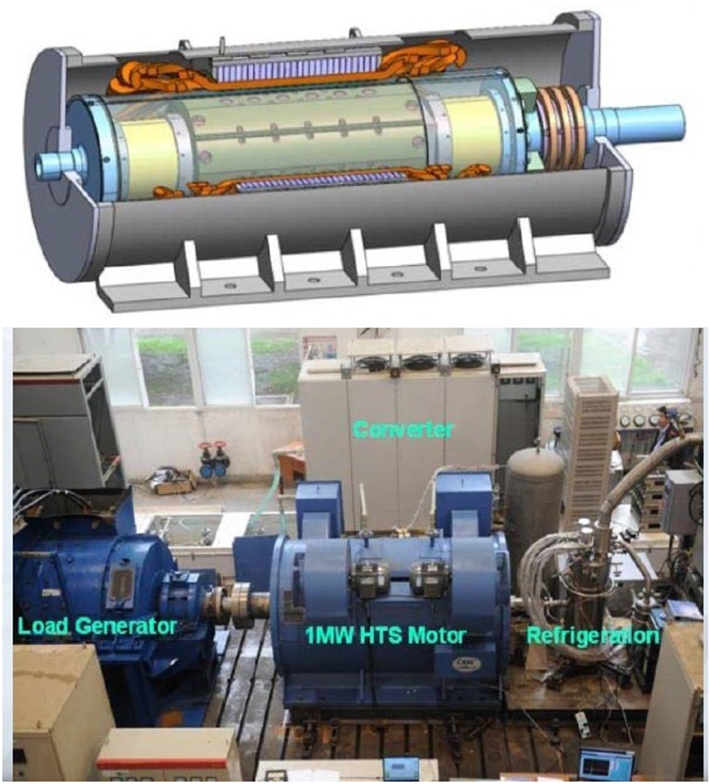
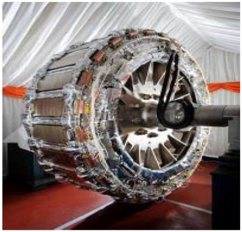
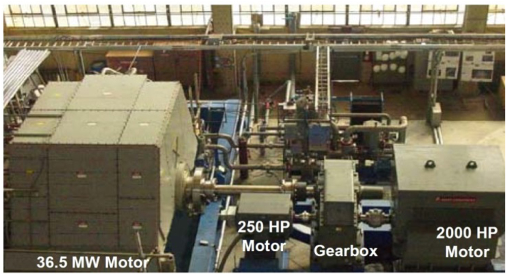
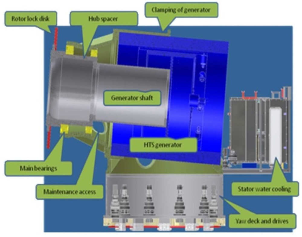
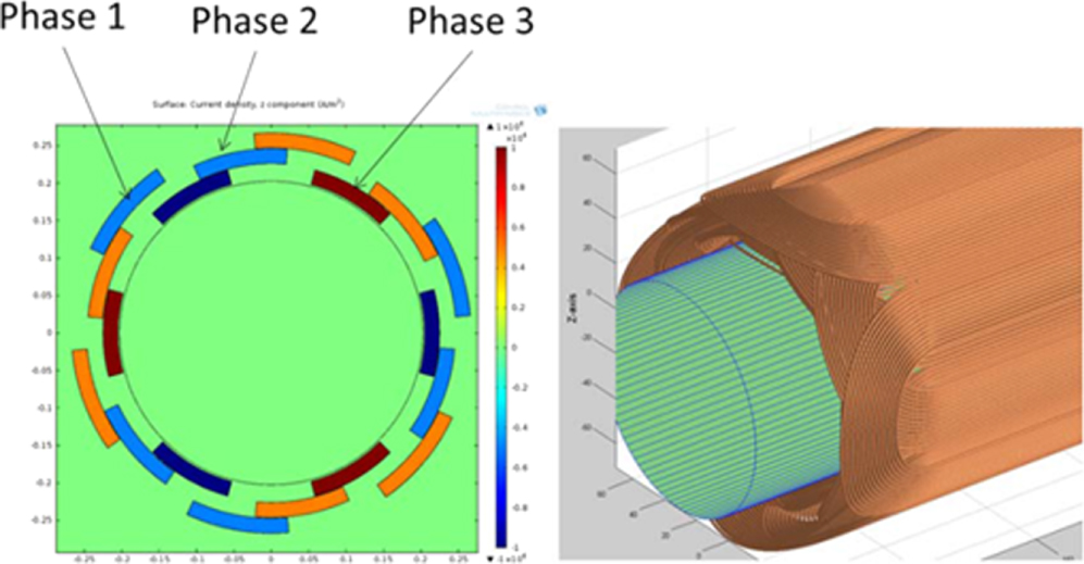
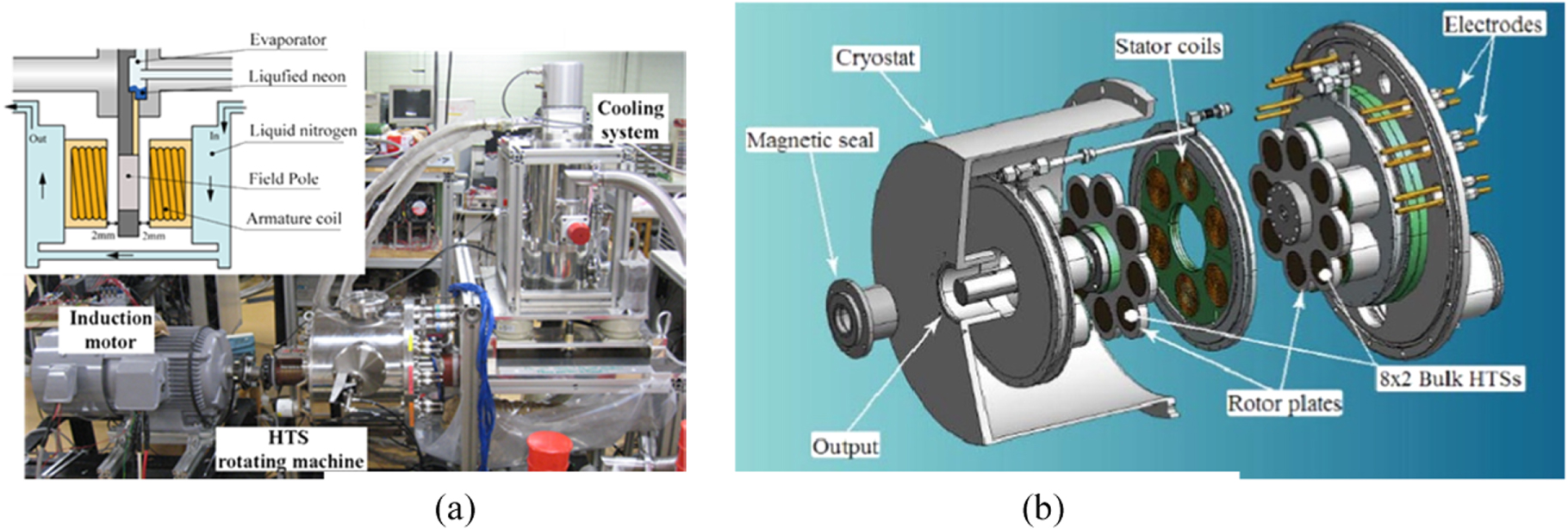
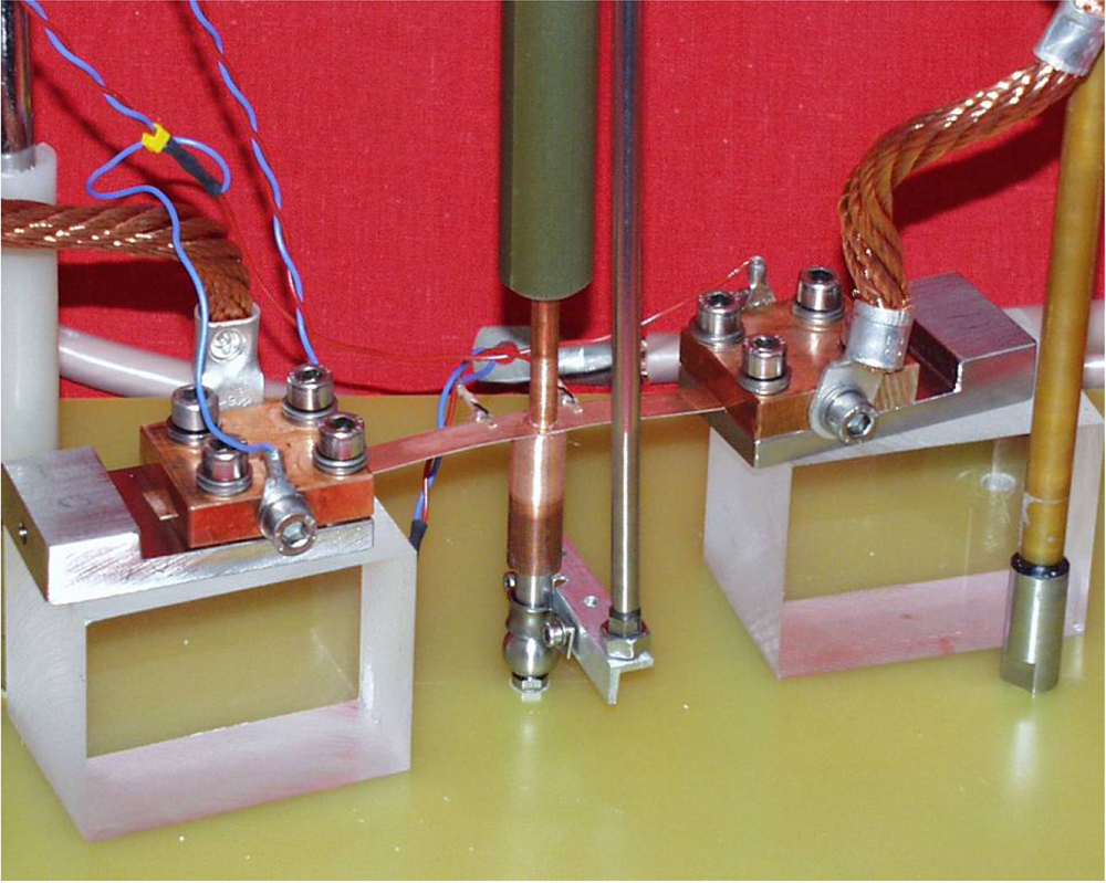
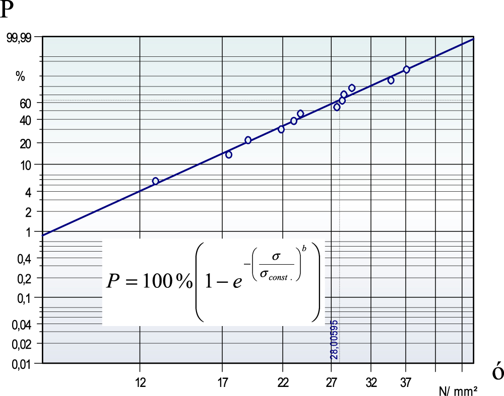
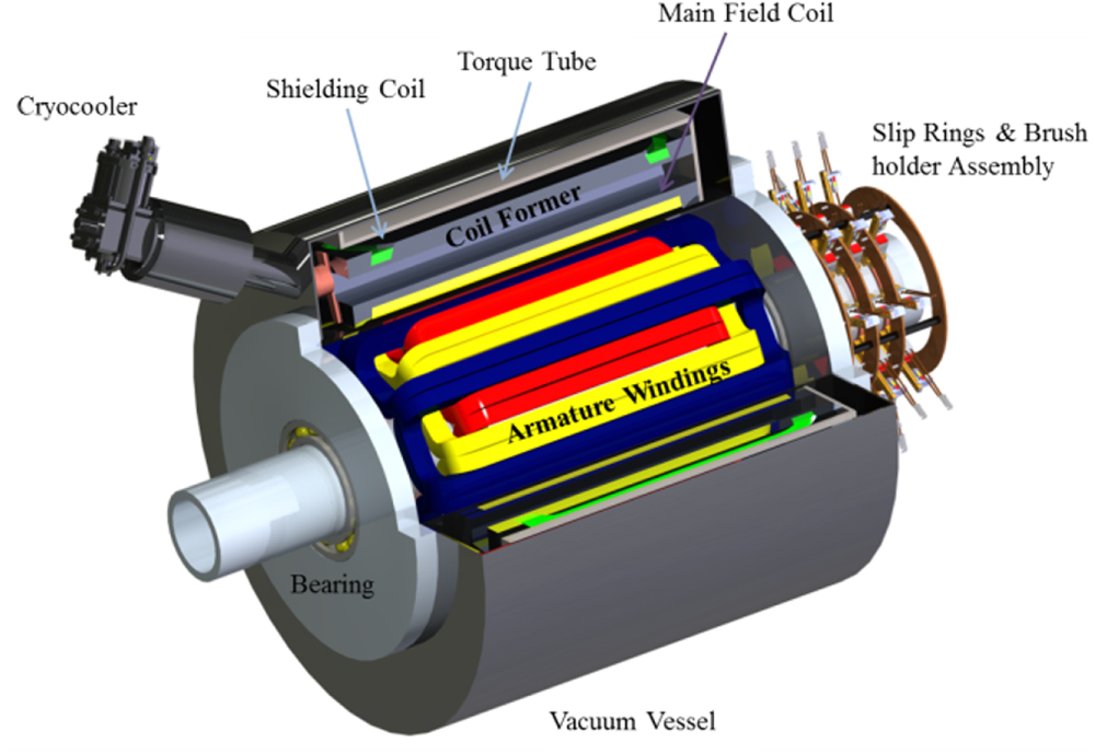
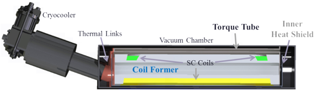
Figure 32. Example of a systemic configuration of an e-aircraft including flows of fuel, coolant, and electricity.
Download figure:
Standard image High-resolution image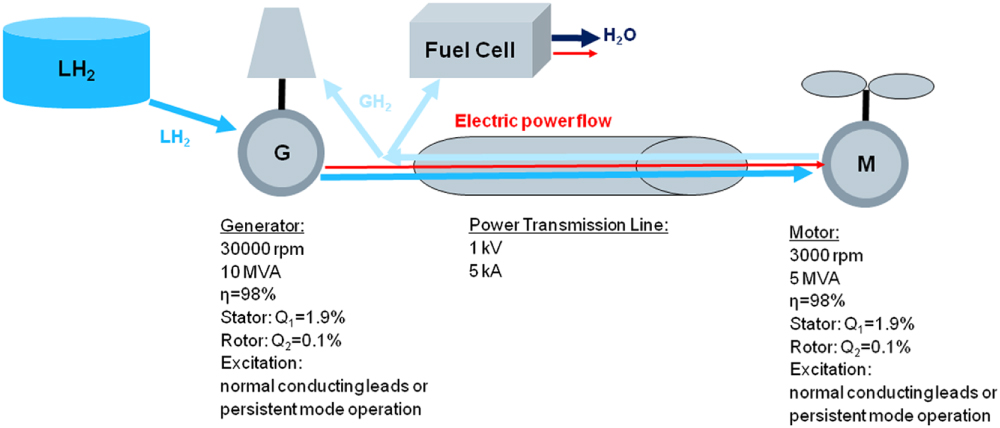
Consider that hydrogen has been selected as the fuel. The fuel is stored in liquid form and thus can be used as the cryogenic coolant for a 20 MVA generator. Liquid hydrogen offers cooling capacity that might allow choosing a fully superconducting machine (both rotor and stator using superconductors). The generator transfers power directly from the superconducting stator via a superconducting power transmission line of low voltage/high amperage, together with the flow of cryogenic coolant, again, directly to the stator windings of one of the multiple motors. The stator configurations of the generator and motor will allow rotational speeds to be adjusted without needing to include power electronics ('electric shaft with electric gearbox'); variable speed/thrust might be controlled by pitch adjustment of the propeller or by the rotational speed of the turbine). After cooling the motor, hydrogen again exits and returns through the outer parts of the power transmission line to eventually enter the gas turbine and/or a fuel cell. The latter might produce power and water for the cabin and the passengers. A remark: the excitation of the rotating machines might be chosen to be transferred by normal conducting leads (allowing control) or by quasi-persistent mode operation of the rotor windings (saving additional weight, given that the mission profile is appropriate for the decay rate of the rotor magnetization).
The numbers listed for the device performance and specifications are a priori best guesses. Nevertheless, it is quite clear that the overall setup according to figure 32 (probably not the optimum) will not be reached while aiming to optimize single components (e.g. maximum generator efficiency or maximum power/weight density of the transmission line).
Concluding remarks
To build the most efficient and sustainable electric aircraft, effort should not be restricted to developing single components, rather to leverage synergies at the system level. Progress in wire performance (e.g. extended window of operation in terms of higher temperature and magnetic field) might stimulate new mission-specific solutions in power-train technology, considering the dynamic variation of operating parameters (e.g. temperature, excitation, amount of fuel and cold) instead of focusing solely on steady operating conditions.
: Appendix
Table A1. Superconducting machine demonstrations.
| Year to reach >TRL 3 | Speed (rpm) | Power (kW) | Conductor type | Cryogenic cooling | Specific power (kW/kg) | Efficiency (%) | Application | Developer |
|---|---|---|---|---|---|---|---|---|
| 1978 | 3600 | 20 000 | NbTi | Liquid He | 0.17 | 99.3 | Utility | GE [85] |
| 1978 | 3600 | 300 000 | NbTi | Liquid He | 1.83 | 99.4 | Utility | Westinghouse [86] |
| 1978 | 3600 | 120 0000 | NbTi | Liquid He | 2.97 | 99.6 | Utility | Westinghouse [86] |
| 1980 | 7000 | 20 000 | NbTi & Nb3Sn | Liquid He | 0.06 | 99.5 | Air Force | GE [87] |
| 1982 | 3000 | 250 000 | NbTi | Liquid He | Utility | GE (Alstom) [88] | ||
| 1983 | 1200 | 2250 | NbTi | Liquid He | Navy | GE [89] | ||
| 1987 | 3000 | 18 | NbTi | Liquid He | Demo | GE (Alstom) [90] | ||
| 1997 | 3600 | 78 700 | NbTi | Liquid He | Utility | Super-GM (Japan) [91] | ||
| 2001 | 1800 | 3725 | BSCCO | Neon boil-off | 0.745 | 97.7 | Industrial | AMSC [92] |
| 2001 | 1500 | 400 | 1G-HTS | Ne-Thermosiphon | 97 | Demo | Siemens [93] | |
| 2003 | 3600 | 1500 | BSCCO | Gaseous He | Utility | GE [94] | ||
| 2004 | 3600 | 4000 | 1G-HTS | Ne-Thermosiphon | 0.58 | 98.7 | Generator | Siemens [95, 96] |
| 2004 | 230 | 5000 | 0.25 | Marine | AMSC [97] | |||
| 2005 | 37 000 | NbTi | Liquid He | Navy | General Atomics [98] | |||
| 2005 | 1800 | 8000 | BSCCO | Ne-Thermosiphon | Utility | AMSC [99] | ||
| 2007 | 120 | 36 500 | Gaseous He | 0.49 | Marine | AMSC [100] | ||
| 2008 | 10 000 | 1300 | BSCCO | Neon boil-off | 8.8 | 98% | Aerospace | GE [101] |
| 2009 | 360 | 7.5 | YBCO | Gaseous He | Marine | NEDO, Japan [132] | ||
| 2009 | 2700 | 160 | 5.3 | FAMU, Georgia Tech, NASA [102] | ||||
| 2010 | 120 | 4000 | 1G-HTS | Ne-Thermosiphon | 0.11 | 94.6 | Marine | Siemens [103], [104] |
| 2010 | 190 | 1000 | BSCCO-2223 tape | Gaseous He | 98 | Marine | KHI [105] | |
| 2011 | 500 | 1000 | BSCCO | Liquid Nitrogen | Marine | Wuhan Institute, China [106] | ||
| 2011 | 200 | 5000 | BSCCO | Cryocooler He | Marine | Doosan [107] | ||
| 2012 | 214 | 17 000 | BSCCO | He gas | Hydro | GE (Converteam) [108] | ||
| 2012 | 160 | 3000 | BSCCO-2223 tape | Gaseous He | 98 | Marine | KHI [109] | |
| 2013 | 250 | 400 | BSCCO | Liquid Nitrogen | 98 | Marine | IHI [110] |
Table A2. Superconducting machine concept designs.
| Year to reach >TRL 3 | Speed (rpm) | Power (kW) | Conductor type | Cryogenic cooling | Power density (kW/kg) | Efficiency (%) | Application | Developer |
|---|---|---|---|---|---|---|---|---|
| 2015 | 600 | 10.5 | YBCO | Liquid neon | Wind | Changwon National University [111] | ||
| 2017 | 20 000 | 2500 | BSCCO | Liquid H2 | 16.66 | Aerospace | AFRL/LEI/HTS-110/VUW [112] | |
| 2019 | 6000 | 10 000 | Nb3Sn | Conduction | 25 | Aerospace | Illinois [113] | |
| 2020 | 12 | 8000 | HTS | Gaseous He | Wind | GE Converteam) [114] | ||
| 2020 | 10 | 10 000 | 0.0833 | Wind | GE [115] | |||
| 10 | 10 000 | MgB2 | Gaseous He | 0.19 | 98 | Wind | KalsiGPS [116] | |
| 11 | 8000 | YBCO | Liquid nitrogen | Wind | AMSC-TECO [117] | |||
| 8 | 10 000 | YBCO 4X wire | Gaseous He | Wind | TECO [118] | |||
| 120 | 40 000 | BSCCO & MgB2 | Gaseous He | 0.496 | 99.4 | Marine | Kalsi GPS [116] | |
| 1800 | 3600 | YBCO | Liquid nitrogen | Marine | TECO [119] | |||
| 10 | 12 000 | YBCO | Gaseous He | 0.0857 | 98 | Wind | Changwon National University [120] |
Footnotes
- 1
However, if rotor winding could be cooled using open-cycle LH2 or cold GHe, it might be possible to employ more conventional machine configurations. This would reduce machine size/mass by one half and improve the efficiency and cost.