
Abstract
The brittle–ductile transition (BDT) widely exists in the manufacturing with extremely small deformation scale, thermally assisted machining, and high-speed machining. This paper reviews the BDT in extreme manufacturing. The factors affecting the BDT in extreme manufacturing are analyzed, including the deformation scale and deformation temperature induced brittle-to-ductile transition, and the reverse transition induced by grain size and strain rate. A discussion is arranged to explore the mechanisms of BDT and how to improve the machinability based on the BDT. It is proposed that the mutual transition between brittleness and ductility results from the competition between the occurrence of plastic deformation and the propagation of cracks. The brittleness or ductility of machined material should benefit a specific manufacturing process, which can be regulated by the deformation scale, deformation temperature and machining speed.
Export citation and abstract BibTeX RIS

Original content from this work may be used under the terms of the Creative Commons Attribution 3.0 license. Any further distribution of this work must maintain attribution to the author(s) and the title of the work, journal citation and DOI.
1. Introduction
Brittle, ductile and brittle–ductile material removal modes are artificially categorized during machining processes [1–4]. The removed material usually experiences plastic deformation in the ductile removal mode (DRM), while brittle fracture occurs during chip formation in the brittle removal mode (BRM) [5]. The material removal mode has a significant effect on the surface integrity of the machined surface [6, 7], machining forces and energy consumption [8, 9], and the life time of machined components [10]. Therefore, a comprehensive understanding of the mechanisms of brittle and ductile removal and their influential factors is essential.
Several aspects determine the material remove mode. The surface topography is one of the most used criterions [11]. The DRM always leads to a smooth and crack-free surface, and plastic plow in the machined surface [8, 12]. However, determining the material removal mode by the surface topography alone is not rigorous. The subsurface damage should also be considered. A single grit scratching experiment of hot-pressed alumina was conducted. Although the groove did not present any observable damage, severe damage with pulverization occurred in the subsurface. And the pile-up on two sides of the groove was due to the side flow of the pulverized material instead of the plastic deformation [13]. Therefore, subsurface damage should also be considered to judge the material removal mode. Plastic deformation mechanisms, including phase transformation [14, 15], slip [16] and twining [17], have been found in the subsurface when the material is removed by DRM. Chip morphology is also used to determine the material removal mode; the layer-type and particle-type chips are associated with DRM and BRM, respectively [18]. Acoustic emission is another effective technology for the in-process monitoring of material removal mode [19, 20].
The material removal mode has been comprehensively studied based on the above identification methods [21–24]. These materials, such as nature stone [25, 26], advanced engineering ceramic [27, 28], semiconductor [29–31], are usually removed with BRM in conventional machining operations, while other materials like metals often present ductile removal characteristics [32–34]. It is worth pointing out that the material removal mode depends on the machining conditions. It has been verified that the transition of the material removal mode may occur in extreme manufacturing, which involves manufacturing at extremely small deformation scales [35], high temperature [36, 37], and high speed machining [38].
The brittle–ductile transition (BDT) in the manufacturing processes has been studied in detail, and some related review articles have been published. However, most of literature focuses on the ductile mode machining of the materials that possess brittle removal characteristics in conventional machining operations by reducing the machining scale [39]. Few reviews involve the effect of other factors, such as machining temperature and stain rate, on the BDT, which are also involved in extreme manufacturing. This paper reviews the BDT in extreme manufacturing, not only brittle-to-ductile transition but also ductile-to-brittle transition. Then, the more comprehensive factors are analyzed, which depicts the effect of the deformation scale, deformation temperature, grain size and strain rate on the BDT. Next, a discussion is arranged to explore the nature of BDT. Finally, the conclusions and outlook are presented.
2. The BDT in the extreme manufacturing
2.1. The manufacturing processes with extremely small scale
The BRM is an obvious characteristic of materials, such as stone, advanced engineering ceramic and semiconductor, which are used in manufacturing processes at the conventional deformation scale. However, the DRM has been found in some manufacturing processes, such as single point diamond turning, ultra-precision grinding and micro-milling [40–42], in which the material removal scales are extremely small.
The critical deformation size is defined as the boundary between BRM and DRM in the manufacturing processes of these materials [43]. For example, in single point diamond turning, a diamond tool with a larger radius and extremely sharp cutting edge combined with extremely small cutting depth and feed is the key to acquiring a thin chip [44]. As for ultra-precision grinding, the ultra-fine grain and nanoscale maximum undeformed cutting thickness related to the grain density and grinding parameters guarantee that more material is removal by the ductile mode [45].
The surface finish is one of the important factors to judge the material removal mode. The machined surfaces with DRM are usually damage-free with material accumulation due to plastic flow; and those with BRM show obvious brittle fracture. The results of the high-speed grinding of SiC depicted that the material removal gradually transitions from brittle to ductile modes with maximum undeformed chip thickness decreases, as shown in figure 1 [46].
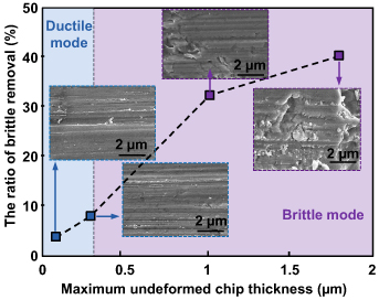
Figure 1. The material removal mode and machined surface morphology of SiC for different maximum undeformed chip thicknesses [46].
Download figure:
Standard image High-resolution imageThe chip morphology is another important factor to judge the material removal mode [47]. The layer-type chips and particle-type chips usually reveal the DRM and BRM, respectively. The chip morphology of a l monocrystalline Si by single point diamond turning is shown in figure 2. It shows the chip morphology transited from particle-type to layer-type as the maximum undeformed chip thickness declined from 690 nm to 20 nm, which indicates the transition of material removal mode [48].

Figure 2. The chip morphology of a single Si crystal by single point diamond turning of (a) dmax= 20 nm and (b) dmax = 690 nm [48].
Download figure:
Standard image High-resolution image2.2. The manufacturing processes at high temperature
Thermally assisted machining is another approach to acquire the DRM of those materials which usually present brittle removal characteristics in conventional machining processes [49]. Compared with small-scale machining processes, the primary aim of thermally assisted machining is to achieve DRM at the conventional machining scale [50]. The key to thermally assisted machining is the provision of an external heat source, including plasma [51], laser beam [52], gas torch [53] and induction heating [54]. The focused research is laser assisted machining because it provides high, local temperature increases on the workpiece in front of deformation zone; only the volume of material to be removed is effectively heated [55]. In this way, the effect of an external heat source on the workpiece can be significantly reduced [56].
Numerous studies have been carried out regarding the use of laser-assisted machining to increase the machinability of materials presenting brittle characteristics at the conventional machining scale [56]. The transition from BRM to DRM has been found due to the involvement of laser beam [57]. The comparative study of conventional and laser-assisted grinding of zirconia (ZrO2) ceramic with a cBN grinding wheel has been implemented. BDT occurred in the subsurface morphology of the machined surface, showed in figure 3, due to the elevated temperature. Obvious cracks can be found on the subsurface due to the BRM in the conventional grinding of ZrO2 ceramic. However, the cracks on the subsurface were suppressed in the laser-assisted grinding because of the BDT. The piled-up material, found in figure 3(b), also presented non-negligible plasticity of ZrO2 ceramic during the laser-assisted grinding [58].

Figure 3. The subsurface morphology of ZrO2 ceramic: (a) conventional grinding and (b) laser-assisted grinding [58].
Download figure:
Standard image High-resolution image2.3. High speed machining
With the development of high-speed cutting machine tools and advanced cutting tool technologies, high-speed machining technologies play an increasingly important role. The advantages of high-speed machining include low cutting forces and temperature, low wear of cutting tools, and high productivity [59, 60]. It is worth pointing out that heat generation in high-speed machining is confined to a thinner area, which produces a high local temperature and temperature gradient. There is less time for heat to enter the workpiece, which results in a lower finished workpiece temperature [61]. However, the chip, cutting tool and tool/chip interface temperature may be more complex [62, 63]. The cutting speed in high-speed machining is significantly improved compared with that of conventional machining. Extremely high cutting speed has been realized by increasing either the diameter of the cutting tools or workpiece and increasing the rotation speed of spindle [64]. In addition, modified light gas guns have been used to study the high-speed machining processes [38, 65]. The chip formation mechanism is one of the study focuses of high-speed machining [66, 67], and Liu et al have conducted a systematic study in this area [68].
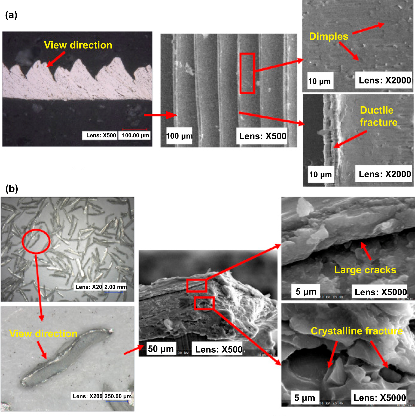
The chip morphology is also the main basis for identifying the material removal mode [69]. Cutting experiments of 7050-T7451 aluminum (Al) alloy with different cutting speeds have been carried out. The chip morphology transforms as cutting speed increases, as shown in figure 4. When the cutting speed was 2500 m min−1, the chip root depicted a large area of dimples spreading over the separation zone, and ductile fracture occurred at the separation point. When the cutting speed was 7000 m min−1, the chip was removed as fragments. Cleavage steps and crystalline fractures were observed on the fracture surface, which are typical characteristics of brittle fracture [70].

Figure 4. The SEM micrographs of the fracture surface on the chip roots (a) cutting speed: 2500 m min−1 and (b) cutting speed: 7000 m min−1 (uncut chip thickness: 0.10 mm) [70].
Download figure:
Standard image High-resolution imageThe evolution of the finished surface with the increase of cutting speed also proves that BDT occurs during high-speed machining. Figure 5 shows the finished surface of orthogonal cutting experiments of Inconel 718. When the cutting speed was 800 m min−1, the smooth machined surface was obtained through DRM. However, when the cutting speed was 7000 m min−1, BRM induced brittle tearing and degraded the surface quality [71].

Figure 5. The finished surface at different cutting speeds: (a) cutting speed is 800 m s−1 and (b) cutting speed is 7000 m min−1 (uncut chip thickness is 0.10 mm) [71].
Download figure:
Standard image High-resolution image3. The factors affecting the BDT
3.1. Deformation scale dependence of brittle-to-ductile transition
As for the deformation scale dependence of brittle-to-ductile transition for these materials presenting the failure of brittle fracture in conventional deformation scale, small-scale testing techniques make the study possible. These testing techniques include indentation and scratching at the micro- and nano-scales and micro-compression and micro-bending [72–74]. Advanced technologies such as (in situ) scanning electron microscope (SEM) and transmission electron microscope (TEM) make the characterization of plastic deformation at micro- or nano-scale more intuitive and credible [75, 76]. It is worth pointing out that nano-scratching can introduce a scratch with varied deformation scale, which may directly present the critical deformation scale of BDT. It could also be determined by micro-compression and micro-bending using a series of specimens with different sizes.
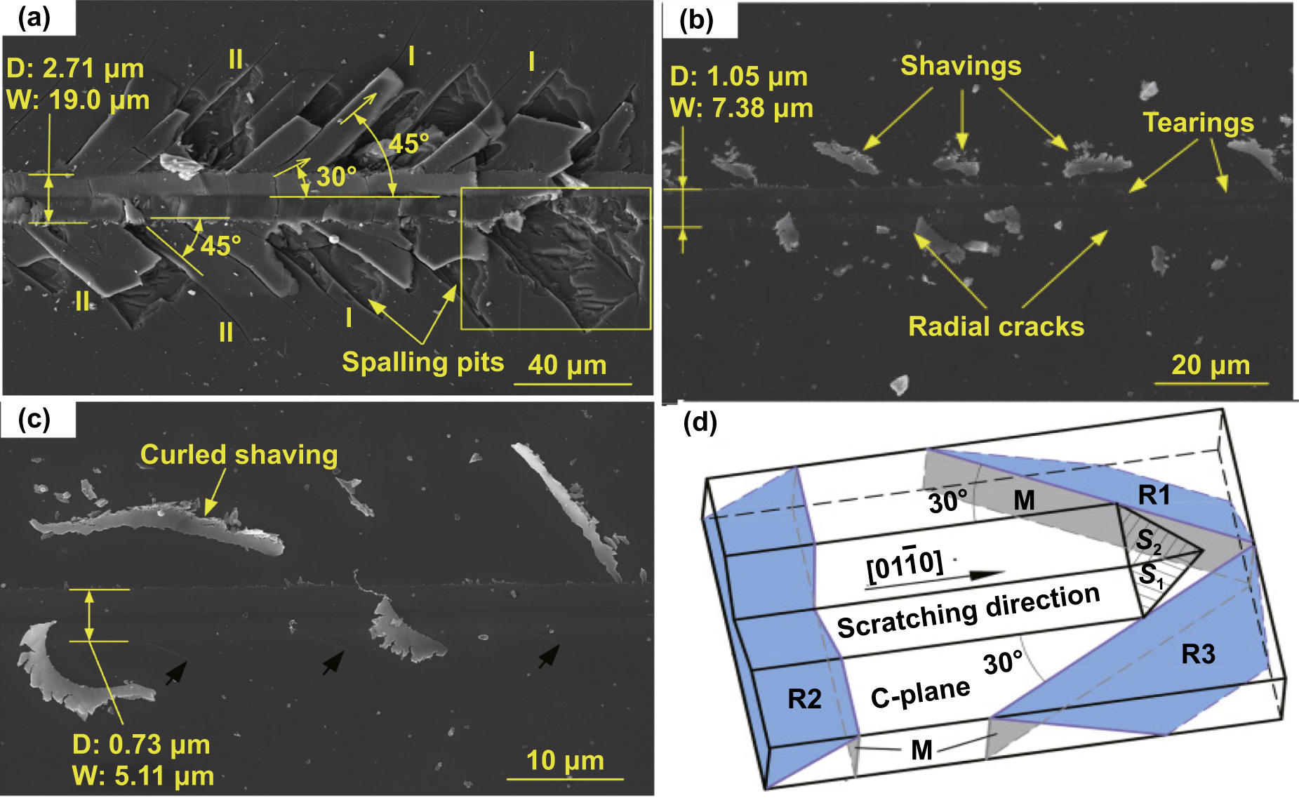
Micro-scratching has been carried out to study the evolution of the deformation mode of sapphire using Vickers indenter, as shown in figure 6 [77]. Deformation can be divided into three stages depending on the scratching depth. In the brittle fracture dominated stage, irregular debris and spalling occurred because of the intersection of lateral and radial cracks, as shown in figure 6(a). In the coexistence stage of plastic deformation and brittle fracture, initial radial cracks and torn and segmented chips appeared, as shown in figure 6(b). In the pure plastic deformation stage, the scratching grooves and long shavings were smooth, and localized plastic flow resulted in curled shavings ejected from the scratches. The results showed that the ductility of sapphire increases as the deformation scale decreases; and pure plastic deformation occurs at sufficiently small deformation scales.
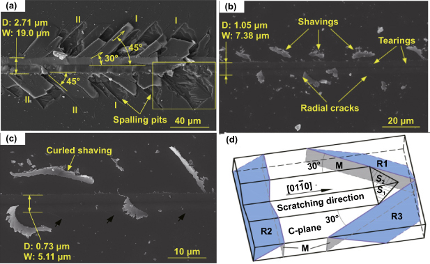
Figure 6. The morphology of the scratching grooves made using a Vickers indenter conducted on the C-plane of sapphire: (a) the scratching depth is 2.71 μm, (b) the scratching depth is 1.05 μm, (c) the scratching depth is 0.73 μm and (d) the schematic illustration of scratching direction [77].
Download figure:
Standard image High-resolution imageBDT due to the decline of the deformation scale has been observed in other materials, such as GaAs, SiC and Si [78, 79]. The mechanisms of deformation scale induced brittle-to-ductile transition have been comprehensively studied. The decline or absence of the natural defect population because of the decreased deformation scale increases the strength of these materials, presenting brittle characteristics in conventional deformation scale, which enables the plastic deformation mechanisms can be activated [80–82]. In general, the material strength and plasticity follows the Weibull distribution, i.e. a larger deformation scale deforms the material in a more brittle fashion due to the higher probability of having a critically oriented flaw in a larger volume [83]. It has been pointed out that cracks could be suppressed, and the plastic deformation could be observed as long as the deformation scale is sufficiently small [84].
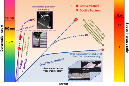
Liu et al proposed that brittle materials could undergo considerable plastic deformation when the deformation scale is small enough, which causes the stress intensity factor KI to be less than the fracture toughness KC due to the three following effects [18, 85]. Firstly, the small deformation scale will lead to the obvious negative rake angle effect in the single point diamond turning, abrasive machining [86, 87], which places extremely high compressive stress on workpiece materials in deformation zone, significantly reducing KI. Secondly, at the mesoscale of deformation (0.1–10 μm), yield strength enhancement due to dislocation hardening related to the dislocation elastic interaction increases KC. Thirdly, at the mesoscale of deformation, strain gradient accommodated by geometrically necessary dislocations strengthens the yield stress, which also increases KC.
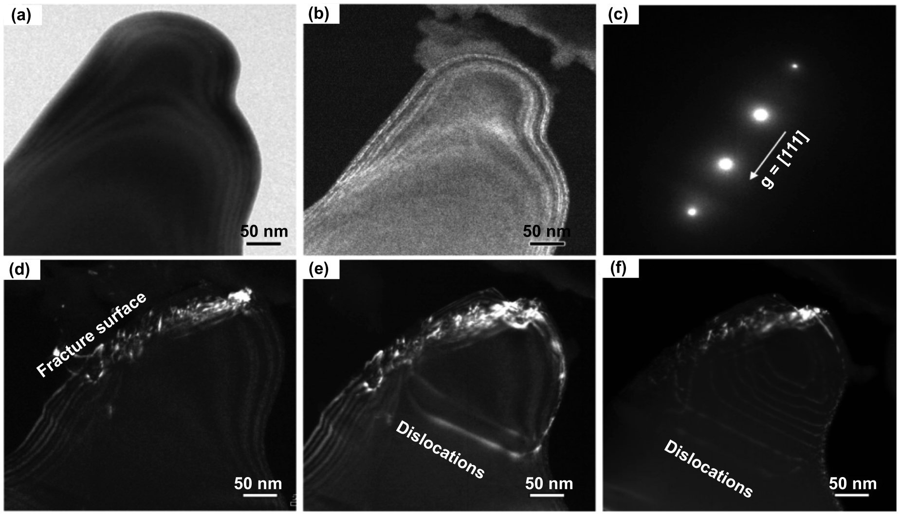
The common plastic deformation mechanisms include the slip, twinning and phase transformation [88]. The most representative example of slip-related plastic deformation is the micro-compression of diamond. It is widely accepted that diamond does not deform plastically at room temperature and often fails in catastrophic brittle fracture. However, a recent study reported the unprecedented dislocation plasticity in the micro-compression of diamond with sub-micrometer pillars [89]. As shown in figure 7, the systematic study showed that the sliding of dislocations primarily determines the plasticity. The defect-free diamond pillar suppresses the cracks and raises the maximum stress level [90], which activates the dislocation.

Figure 7. Multiplication and motion of dislocations in a diamond pillar (a) and (b) are the bright-field and dark-field TEM images of the diamond pillar respectively, (c) is the selected area for the electron diffraction pattern, (d) is a fracture surface of diamond due to first-stage compression, and (e) and (f) are the dislocations emitted from the fracture surface in subsequent deformation [89].
Download figure:
Standard image High-resolution imageThe decline of deformation scale may activate other plastic deformation mechanisms. Compared with macroscopic specimens, the micro-compression of polycrystalline ZrO2 depicted the absence of defects significantly increases compressive strength up to 8 GPa with a failure strain of 7%, which is four times larger than that of macroscopic tests. The higher stresses activate plastic deformation. The TEM and STEM observations suggest that the phase transformation was the main plastic deformation mechanism [91]. In addition, the decline of the deformation scale induces twinning and a combination of the three kinds of plastic deformation mechanisms [92].
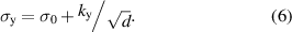
The critical deformation size has been proposed, which is expressed as following [79, 83, 93]:
where the dcrit is the critical deformation scale of brittle-to-ductile transition; KC and σy is the fracture toughness and yield stress respectively; λ is the flaw geometry constant. It has been pointed out that when the deformation scale is less than dcrit, the smaller deformation zone cannot provide sufficient elastic energy for the rapid crack propagation, and material failure occurs by plastic deformation [83].
Bifano et al [94] proposed an empirical equation for the depth of BDT. The critical penetration depth hc is given by:
where E is the Young's modulus of materials, H is the hardness, KC is the fracture toughness, σy is the fracture toughness and yield stress respectively and ψ is BDT factor of materials.
The brittle-to-ductile transition induced by the decline of deformation size has been comprehensively studied in experiments, and the representative experimental results are listed in table 1.
Table 1. The results of BDT induced by the decline of deformation size.
| Materials | Test method | Critical load or size of brittle-to-ductile transition | Note | Reference |
|---|---|---|---|---|
| Single-crystal silicon | Nanoindentation | Depth: 54.63 nm | Indenter type: Berkovich | [95] |
| Load: 138.64 mN | Tip radius of indenter: 50 nm | |||
| Crystal plane: (1 0 0) | ||||
| Single-crystal silicon | Nanoscratching | Load: 11–16 mN | Indenter type: Rockwell (90°) | [96] |
| Tip radius of indenter: 1 µm | ||||
| Crystal plane: (1 0 0) | ||||
| Scratching direction: <1 0 0> | ||||
| Single-crystal silicon | Nanoscratching | Depth: 36 nm | Indenter type: Cantilever with diamond coated tip | [97] |
| Load: 118 µN | Tip radius of indenter: 100 nm | |||
| Crystal plane: (1 0 0) | ||||
| Scratching direction: <1 0 0> | ||||
| 6H–SiC | Nanoscratching | Depth: 75 nm | Indenter type: Berkovich | [98] |
| Load: 12.2 mN | Tip radius of indenter: 940 nm | |||
| Crystal plane: (0 0 0 1) | ||||
| YAG | Nanoindentation | Load: 10 mN | Indenter type: Berkovich | [99] |
| Tip radius of indenter: 90 nm | ||||
| Crystal plane: (1 1 1) | ||||
| AlN ceramics | Nanoscratching | Depth: 420–600 nm | Indenter type: Berkovich | [100] |
| Tip radius of indenter: 90 nm | ||||
| RB-SiC ceramics | Nanoindentation | Load: 60–70 mN (Si matrix) | Indenter type: Vickers | [101] |
| Load: 40–60 mN (SiC particle) | ||||
| Lithium luminosilicate glass ceramics | Nanoscratching | Depth: 335.10 nm | Indenter type: Berkovich | [102] |
| Load: 268.60 mN | Tip radius of indenter: 100 nm |
3.2. Deformation temperature dependence of brittle-to-ductile transition
In addition to the reduced deformation scale, elevated temperature could also enable plasticity in these materials that present brittle fracture at room temperature. Elevated temperature induced brittle-to-ductile transition has been extensively studied. The micro-compression of monocrystalline Si with a pillar diameter of 2 μm has been carried out at different temperatures and a constant loading rate of 0.5 mNs−1; the results are shown in figure 8 [103]. The micro pillar directly failed in brittle fracture at room temperature. However, a BDT was found in which the micro pillar deformed plastically without catastrophic failure, although some cracking was still observed in figure 8(b). Figure 8(c) depicts a micro pillar that had experienced substantial plastic deformation, which verifies that the cracks were suppressed in the monocrystalline Si micro pillar. These results are consistent with an earlier study, which reported that the BDT temperature was about 500 °C [104]. Similar results have been found in the micro-compression of single crystal MgAl2O4 [105] and small punch tests of polycrystalline Al2O3 [106]. These results demonstrate that elevated temperature can induce the BDT.

Figure 8. The change of deformation mode with different deformation temperature of (a) 25 °C, (b) 200 °C and (c) 500 °C [103].
Download figure:
Standard image High-resolution imageOne of the research focuses of elevated temperature induced plasticity is to expand the ductile regime. The scratching test of RB-SiC ceramics was implemented at varied temperatures. The wedge scratching mode was used with a Vickers indenter to study the ductile-to-brittle transition under different scratching temperatures. Figures 9(c)–(f) shows that the scratch length undergoing plastic deformation increased with the rise of temperature, which indicates a positive correlation between the critical deformation scale of BDT and deformation temperature [107].
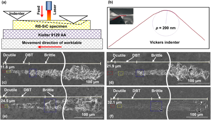
Figure 9. Elevated temperature scratching of RB-SiC: (a) the schematic illustration of the scratching test, (b) the Vickers indenter used in the test with the round tip, (c) the scratch at room temperature, (d) the scratch under at 200 °C, (e) the scratch at 600 °C and (f) the scratch at 900 °C [107].
Download figure:
Standard image High-resolution imageThe mechanism of elevated temperature induced brittle-to-ductile transition is related to the thermal activation. The dislocation motion is more difficult because of the high energy of covalent and ionic bonds in some materials at room temperature [108]. Therefore, ionic-bonded and covalent-bonded materials, such as semiconductors and ceramics, always present catastrophic brittle fracture. Plastic deformation involves dislocations that move from one equilibrium position to the next, during which the dislocation must overcome the Peierls–Nabarro lattice resistance [109]. As shown in figure 10, each peak represents the resistance applied on the dislocation during the dislocation motion process. The area under the curve represents the energy consumed during the dislocation motion. The atoms in solids always vibrate randomly near their equilibrium positions. Atoms vibrate more rapidly at higher temperatures, which increases the thermal energy ΔG and decreases the resistance energy consumed during the dislocation motion process. Therefore, dislocations move easily at high temperatures [110, 111]. Increased temperatures facilitate dislocation motion better than brittle fracture, which contributes to the brittle-to-ductile transition [112].
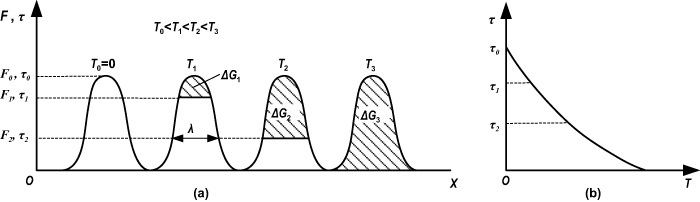
Figure 10. The effect of deformation temperature on the dislocation motion: (a) schematic of a dislocation overcoming barriers with the assistance of thermal energy and (b) the relationship between the deformation temperature and the stress used for overcoming barriers [113].
Download figure:
Standard image High-resolution imageThe competition between dislocation motion and brittle fracture is quantitatively described in the following equations [112, 114]:
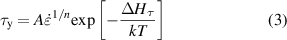

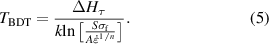
Where τy is the yield stress, A and n are material constants, ΔHτ is the energy parameter related to the activation of dislocation motion, k is the Boltzmann constant, T is the deformation temperature, σf is the fracture stress, τf is the corresponding shear stress of σf, S is Schmid factor. τy and τf are the critical shear stresses for dislocation motion and fracture, respectively. There is a negative correlation between τy and T. τy for a crystal is weakly temperature dependent and can be regarded as a constant [112]. In general, τy is larger than τf for these materials presenting brittle fracture at room temperature. However, BDT can be acquired by rising the deformation temperature. The brittle-to-ductile transition temperature TBDT could be obtained by combining equations (3) and (4), which is expressed as [112, 115, 116]:
The BDT induced by the elevated deformation temperature has been comprehensively studied, and the representative experimental results are listed in table 2.
Table 2. The results of BDT induced by the elevated deformation temperature.
| Materials | Test method | Brittle-to-ductile transition temperature | Note | Reference |
|---|---|---|---|---|
| Single-crystal silicon | Pillar indentation splitting test | About 250 °C | The diamond cube corner indenter was used and a facet edge of the cube corner was kept aligned with the (0 1 0) plane | [117] |
| GaAs | Micro-pillar compression | 300 °C | The diameter of micro-pillar is 2 µm. | [103] |
| GaAs | Indentation experiment | 200 °C | Indenter type: Vickers | [112] |
| Crystal plane: (0 0 1) | ||||
| GaAs | Four-point bend test | 300 °C–380 °C | Sample size is 35 × 3 × 1 mm, and the 35 × 3 mm2 top and bottom faces of the sample were cut parallel to the (0 0 1) plane. | [112] |
| ZrO2and Al2O3 | Small punch test | 1100 °C (For ZrO2) 1250 °C (For Al2O3) | Disk-shaped specimen with the diameter of about 10 mm and thickness of 0.5 mm. | [106] |
| 4H–SiC | Compression experiments | 1100 °C( = 3.6 × 10⁻⁵ s−1)
1030 °C( = 3.6 × 10⁻⁵ s−1)
1030 °C( = 2.6 × 10⁻⁵ s−1) = 2.6 × 10⁻⁵ s−1) | Parallelepiped-shaped samples with the basal (0 0 0 1) plane at 45° to the compression axis. | [118] |
| MgAl2O4 | Micropillar compression | About 200 °C | The diameter of micropillar is 2.5 µm. | [105] |
3.3. Grain size dependence of ductile-to-brittle transition
White layer is a common phenomenon in manufacturing processes for these materials presenting obvious plasticity in conventional manufacturing, especially for high-speed machining, in which the grain refinement has been widely observed [119–121]. The grain distribution below the machined surface is shown in figure 11. It depicted that the white layer can be divided into two layers including the recrystallization (RX) layer and transition layer. There were 200 nm sized nanocrystal grains in the RX layer with large angle grain boundaries. A transition layer with low angle grain boundaries and sub grains formed below the RX layer. There were larger grains with small angle grain boundaries in the deformed buck layer [122]. It has been reported that brittleness and hardness in the white layer were significantly higher compared with the buck material due to the severe grain refinement [121, 123], which contributes to the ductile-to-brittle transition in the machining processes.
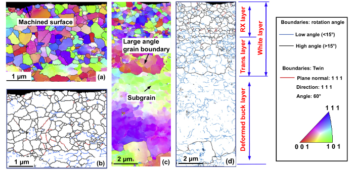
Figure 11. Subsurface grain distribution of nickel (Ni)-based superalloy (S135H) after orthogonal cutting (a) and (b) at 0–2.5 µm from the machine surface, (c) and (d) at 0–12 µm from the machine surface [122].
Download figure:
Standard image High-resolution imageThe grain size has a significant effect on the mechanical properties of materials, which can be expressed by the Hall–Petch relationship [124, 125]. The following formula quantitatively establishes the relationship between the yield strength and grain size, where the yield stress increases as the average grain size increases [126]:
where σy is the yield stress, σ0 is a material's constant for the starting stress for dislocation movement, ky is the strengthening coefficient (a constant specific to each material), and d is the average grain diameter.
The relationship between the yield stress or hardness and the average grain size of copper is shown in figure 12, which was summarized by Tschopp et al [127]. It has been reported that yield strength could be improved by more than five times when the materials transit from micro-sized to nano-sized grains [128] (figure 12).
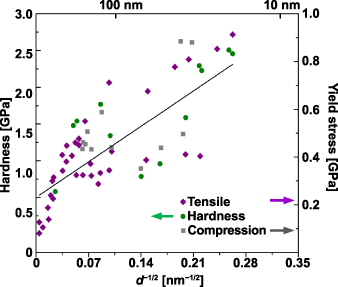
Figure 12. The relationship between yield stress or hardness and the grain size of copper [127].
Download figure:
Standard image High-resolution imageHowever, the elongation of materials decreases with the decrease of grain size. The relationship between elongation and average grain size summarized by Liu et al is shown in figure 13 [129]. They concluded that brittleness increased with the decrease of grain size. Therefore, the ductile-to-brittle transition may occur in materials with extremely small grain size.
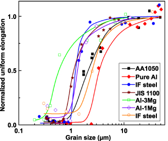
Figure 13. Grain size dependence of uniform elongation [129].
Download figure:
Standard image High-resolution imageThe brittle fracture of nano-grained Cu and Ni with ultrahigh strength has been found in the tensile test, which was identified by fracture morphology [130], as shown in figure 14. The strengthening mechanism for fine-grained materials is that the dislocation slip is substantially suppressed by grain boundaries of the extremely small grains [131]. However, grain boundary sliding or diffusional creep is not active enough to accommodate plastic straining at ambient temperature, which leads to brittle fracture [132].

Figure 14. The stress–strain curves for Ni and Cu [130].
Download figure:
Standard image High-resolution imageIt has been summarized that the plastic deformation mechanisms differ according to grain size and transit smoothly with the decline of average grain size [133]. The dominated plastic deformation mechanism is dislocation motion when the grain size is larger than 10 nm, in which the Hall–Petch relationship is widely confirmed [134, 135]. However, strength and brittleness decrease when the grain size is less than about 10 nm, which is called the inverse Hall–Petch effect [136]. This effect is the result of other plastic deformation mechanisms, such as grain boundary sliding and grain rotation [137]. It is worth noting that the size of refined grain during the high speed machining usually larger than 10 nm [138–143]. Therefore, the decline of strength and brittleness with the decrease of grain size is rarely involved in extreme manufacturing.
3.4. Strain rate dependence of ductile-to-brittle transition
Machined materials are often subjected to dynamic loadings. The mechanical behaviors of materials subject to high strain loading differ from those subject to static or quasi-static loading [144, 145]. The different mechanical test methods are used to acquire similar strain rates consistent with specific manufacturing processes, as shown in figure 15 [71, 146, 147].
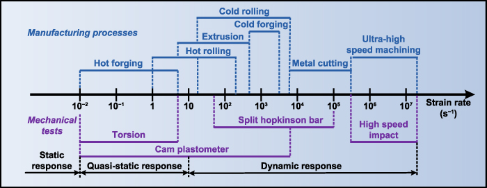
Figure 15. The strain rate ranges for different manufacturing processes and the corresponding test methods [71].
Download figure:
Standard image High-resolution imageIt has been reported that both the tensile strength and yield strength of these materials presenting obvious increase of plasticity as the strain rate increases, and plastic failure strain declined with the growth of strain rate [148], as shown in figure 16. The connecting curve EDCBA represents the critical condition where the material fails, which was named the 'fracture locus.' figure 16 shows that the brittleness increased as the strain rate increased. The ductile-to-brittle transition occurs as long as the strain rate is high enough.
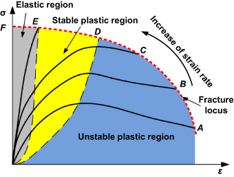
Figure 16. The mechanical response of materials under different strain rates [148].
Download figure:
Standard image High-resolution imageThe stress wave theory is often used to analyze the mechanical behaviors of materials that have high strain rates. According to the theory, the brittleness induced by high strain rate should be defined as pseudo brittleness. The materials subject to high strain rate deform locally, near the impact positions, and the rest of the part presents no obvious plastic deformation, which is a mechanism of pseudo brittleness [149]. The materials fail in a ductile manner when pseudo brittle fracture occurs. The velocity of the stress wave can be expressed by the following equations [150, 151]:
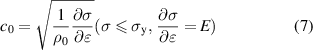
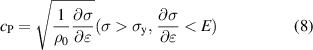
where c0 and cp are the elastic and plastic stress velocities, respectively. ρ0 is the density of materials. σ and  are the stress and strain, respectively. σy is the yield stress, and E is Young's modulus. The above equations suggest that the plastic stress velocity is always less than the elastic stress velocity, which cooperates with unloading waves to make materials deform locally during the impact process.
The unloading waves mainly include the reflected elastic wave generated at the end of specimens and the elastic wave induced by the unloading impact, as shown in figures 17(a) and (b), respectively [113]. As for the effect of the reflected elastic wave generated by the end of specimens on the deformation distribution, it is depicted by a bar with length of l impacting with a rigid object. When the time t is from zero to l/c0, both the elastic and plastic compression waves propagate from the left end to the right end of the rod. The elastic compression wave propagates faster than plastic compression wave. When the elastic compression wave reaches the right end at time l/c0, the reflection generates the elastic tensile wave. Then, the elastic tensile wave, functioning as an unloading wave, propagates from the left end to the right end and unloads the elastic and plastic compression waves in turn, which propagate from the left to right. When the elastic tensile wave reaches the left end at time 2l/c0, the elastic and plastic compression waves are completed unloaded. Finally, the local residual plastic deformation zone with length x1 forms, which depicts the local deformation of the impacted material. The effect of the elastic wave, induced by the unloading of impact on the deformation distribution is shown in figure 17(b). It is depicted by a bar with semi-infinite length impacting with a rigid object. The elastic tensile wave, functioning as the unloading wave, is generated at time tu, and the unloading process of earlier elastic and plastic compression waves is similar to those shown in figure 17(a).

Figure 17. The effect of unloading waves on the deformation distribution of (a) the elastic wave induced by reflection and (b) the elastic wave induced by the unloading of impact [111].
Download figure:
Standard image High-resolution imageThe difference between the elastic wave velocity and the plastic wave velocity and the unloading waves cause the materials subject to impact to deform locally. The most obvious example of this is the Taylor impact test, in which the projectiles are accelerated to impact a rigid wall [152, 153]. Five distinct deformation and fracture modes in the projectile during Taylor impact tests for steels have been reported, as shown in figure 18 [154–157]. The projectiles always deform or fracture locally close to the impact end.
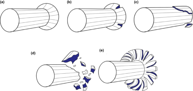
Figure 18. The five distinct deformation and fracture modes in the projectile: (a) mushrooming, (b) tensile splitting, (c) shear cracking, (d) fragmentation and (e) petalling [154].
Download figure:
Standard image High-resolution imageWhen a bar with velocity V is impacted, the strain at the impact end is V., and their relationship can be expressed as the following formula [71, 149]:
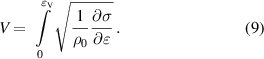
The plastic wave velocity Vcr is expressed as following:
where m is the strain when ∂σ/∂ is zero, which means that the plastic wave velocity is zero. If the velocity of impact V exceeds plastic wave velocity Vcr, the strain at the impact end will be larger than m, which is the stain corresponding to tensile strength. The materials will fail in the form of pseudo brittle fracture.
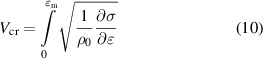
Dislocation kinematics provides another perspective to explain the brittle-to-ductile transition when materials subject to impact. Plastic deformation is the combined result of dislocation motion, mechanical twinning and phase transformation [158]. Figure 19 expresses the plastic deformation at different strain rates when only dislocation movement is considered. It is worth pointing out that the variation of stress was due to the change of strain rate. In general, there is a positive correlation between stress and strain rate for a specific strain [159]. The dominant factors affecting the mean dislocation velocity is thermal activation, pure drag and relativistic effect in turn as the stress increases, and the mean dislocation velocity is always less than the shear wave velocity due to the relativistic effect [160]. The velocity of the dislocation relative to the loading tends toward zero with increasing loading velocity. Therefore, the dislocation seems to be fixed when the material has a high enough strain rate, which leads to the ductile-to-brittle transition.
Figure 19. The relationship between stress and mean dislocation velocity [160].
Download figure:
Standard image High-resolution imageSevere grain refinement also contributes to the ductile-to-brittle transition of materials presenting obvious plasticity. The grain refinement is much more severe during impact deformation than quasi-static deformation. The results of metal particle impact tests suggest that the impact process can lead to the formation of nano-sized grains, in which the dynamic RX caused by adiabatic shear instability plays a major role [161, 162]. The grain refinement is shown in figure 20.
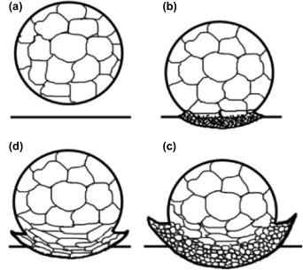
Figure 20. The grain refinement process of a single titanium powder particle subject to impact of (a) spraying titanium particle onto the substrate, (b) entanglement of dislocations, (c) formation of dislocation cells and sub-grains; and (d) breaking-up, rotation and recrystallization of sub-grains [161].
Download figure:
Standard image High-resolution image4. Discussion
Covalently or ionically bonded materials generally present brittle characteristics because of their high bond energy, which makes plastic deformation more difficult to induce than nucleation or propagation of cracks in conventional deformation conditions. On the contrary, the metallic bonded materials present ductile characteristics due to their low bond energy [108]. However, there is a mutual transition between the brittleness and ductility of materials. The nature of BDT is the competition between the ease of plastic deformation including dislocation motion, twining and phase transformation, and crack propagation. The mutual transition relationship between brittleness and ductility of the material can be vividly described by an ouroboros as shown in figure 21, which is a symbol of infinite circulation. The factors that can promote this circulation include deformation scale, deformation temperature, strain rate and grain size.

Figure 21. The mutual transition relationship between brittleness and ductility of materials.
Download figure:
Standard image High-resolution imageThe BDT described in this review is shown in figure 22. With regard to the deformation scale, the resistance of crack propagation increases as deformation scale decline, because the decreased deformation zone does not provide sufficient elastic energy for the rapid propagation of cracks [83], significantly improving the fracture strength [163]. The resistance of crack propagation exceeds that of plastic deformation when the deformation scale is small enough, which induces plasticity in materials that usually present brittle characteristics. When the material is removed at a small enough scale, the materials remove through the ductile mode instead of the brittle mode. As for the deformation temperature, the resistance of plastic deformation decreases with the increase of deformation temperature because of the rise of thermal energy [105, 106, 164]. The resistance of plastic deformation is lower than that of crack propagation as long at high enough deformation temperatures, which facilitates brittle-to-ductile transition. Thermally assisted machining can ensure that the material is removed with ductile mode at relatively large deformation sizes because the heat expands the plastic domain of machined materials. Grain boundaries could improve the resistance of plastic deformation. The ductile-to-brittle transition occurs when the resistance of plastic deformation is improved above that of crack propagation. As for the deformation rate, the dislocations seem to be fixed when the materials are subject to high enough strain rates, which is a way of improving the resistance of plastic deformation to induce the ductile-to-brittle transition. Therefore, the materials that present ductile characteristics at conventional deformation rate can be removed with brittle mode as long as the cutting speed is high enough.
Figure 22. The BDT in the extreme manufacturing.
Download figure:
Standard image High-resolution image
The brittleness or ductility of machined materials should benefit a specific manufacturing process, which can be regulated based on the BDT analyzed in this review. As for the manufacturing of semiconductor wafers, which present typical brittle removal characteristics in conventional machining conditions, ductile removal in the finishing process should be guaranteed by the polishing process with the extremely small deformation scale to acquire a defect-free machined surface [165, 166]. Advanced engineering ceramics are in increasing demand in automotive, aerospace and military fields due to their high temperature strength, low density and good wear resistance. The machining of these ceramics is expensive due to the short tool life and low machining efficiency. In addition, surface and subsurface damage is often introduced in conventional machining conditions, which severely reduces the service life of machined components [167]. The DRM with larger deformation scale could be acquired in the thermally assisted machining of these ceramics [49, 168].
The suitable improvement of the brittleness of those materials presenting high ductility in conventional machining conditions helps improve the machining performance in extreme manufacturing [70]. For example, the cutting force could be reduced in the high-speed machining of ductile materials due to the strain rate induced ductile-to-brittle transition, which may benefit the machining of low rigidity components with high precision [169, 170]. In addition, energy consumption could be reduced in high-speed machining due the strain rate induced ductile-to-brittle transition depicted by the area under the stress–strain curves, as shown in the figure 22 [171], which may be related to the low cutting temperatures present in high-speed machining operations. Another example is the lower surface roughness in high-speed machining [172]. The side flow of workpiece materials due to high ductility makes the measured surface rougher than those achieved through theoretical calculations [173]. The side flow may decrease due to the reduced ductility in high-speed machining operations, which contributes to the low roughness. However, the machining speed should be limited because the high brittleness may worsen the surface integrity [71], and the most suitable machining speed for specific materials could be determined based on the BDT of the machined materials.
5. Conclusions and outlook
This review discusses the BDT of material mechanical behaviors and its effect on the material removal mode in the extreme manufacturing. The following conclusions are presented:
- (a)The decline of deformation size and the rise of deformation temperature induce the brittle-to-ductile transition of material mechanical behaviors; in contrast, the decline of grain size and the rise of strain rate could induce the ductile-to brittle transition of material mechanical behaviors.
- (b)The nature of the mutual transition between brittleness and ductility of material is the competition between the ease of occurrence of plastic deformation and crack propagation.
- (c)The brittleness or ductility of machined materials should benefit a specific manufacturing process, which can be regulated by the deformation scale, deformation temperature and machining speed.
The main factors affecting the BDT in the extreme manufacturing are reviewed. In fact, the BDT can be governed by coupled factors, such as thermal-mechanical coupling, because the majority of manufacturing processes involve coupled multi-factors. However, the majority of studies aim to analyze the BDT single factor and avoid multiple factors through the design of experiments or numerical simulations, which creates a gap between the BDT mechanisms and its application in manufacturing processes.
Moreover, the extreme manufacturing processes involving high-temperature, high-speed and energy fields make the study of BDT more challenging. Traditional quasi-static, micro- or nano-tests cannot simulate these extreme conditions. New testing technologies should be developed to promote the study of BDT under high-speed and high-temperature conditions and in energy fields. Specifically, the study of BDT in energy fields, such as chemical and magnetic fields, should be paid more attention since it might be highly beneficial to the development of energy assisted manufacturing technologies.
Acknowledgment
The authors would like to acknowledge support from the National Natural Science Foundation of China (Grant No. 51835004).