
Abstract
Inspired by natural porous architectures, numerous attempts have been made to generate porous structures. Owing to the smooth surfaces, highly interconnected porous architectures, and mathematical controllable geometry features, triply periodic minimal surface (TPMS) is emerging as an outstanding solution to constructing porous structures in recent years. However, many advantages of TPMS are not fully utilized in current research. Critical problems of the process from design, manufacturing to applications need further systematic and integrated discussions. In this work, a comprehensive overview of TPMS porous structures is provided. In order to generate the digital models of TPMS, the geometry design algorithms and performance control strategies are introduced according to diverse requirements. Based on that, precise additive manufacturing methods are summarized for fabricating physical TPMS products. Furthermore, actual multidisciplinary applications are presented to clarify the advantages and further potential of TPMS porous structures. Eventually, the existing problems and further research outlooks are discussed.
Export citation and abstract BibTeX RIS

Original content from this work may be used under the terms of the Creative Commons Attribution 3.0 license. Any further distribution of this work must maintain attribution to the author(s) and the title of the work, journal citation and DOI.
1. Introduction
With the rapid development of material science and manufacturing engineering, numerous complex structures are constructed and applied in diverse engineering fields. Regardless of whether these structures are composed of metallic, non-metallic inorganic materials, polymers, or any other more complex materials, most of the structures currently used in industry are classified as solid structures. Hence, the porosities of solid structures can be regarded as zero. In fact, the internal pores are even considered as defects due to the low manufacturing quality. However, there are lots of porous structures exist in nature with outstanding performances, such as bones, corals, honeycombs, woods, etc [1, 2]. Inspired by these natural structures, more and more attempts are made to generate artificial bionic porous structures.
The design strategies of porous structures are strictly restricted by the development of manufacturing technologies. Due to the complex topology and intricated internal pores, conventional cutting or milling methods are powerless to fabricate porous structures which are similar to natural architectures. Several special technologies are proposed to generate porous features, such as salt leaching, gas-foaming, and phase-separation followed by freeze-drying [3]. Yet, the basic demands such as the pore shape, size, and connectivity can hardly be controlled. Fortunately, revolutionary additive manufacturing provides new solutions to fabricating porous structures [4]. The constraints of topological complexity on the manufacturing process are greatly alleviated. However, how to design porous structures with controllable geometries and performances, reliable manufacturing quality, and broad application prospects is still a critical problem.
In this review, the design methods of porous structures can be summarized as three kinds according to the degree of control over geometric features and the degree of dependence on additive manufacturing. The two-dimensional honeycombs and three-dimensional foams can be regarded as typical examples of the first kind of porous structures [5, 6]. Some simple honeycombs can be easily fabricated by conventional cutting technologies. Due to the two-dimensional geometric features, honeycombs are utilized as cores of sandwich panels in most current applications. As mentioned before, numerous porous foams are generated by salt leaching or gas-foaming. The porous features and performances of foams are not easy to control. Hence, lattice structures which are composed of struts and nodes were developed and can be regarded as the second kind of porous structures [7]. The geometries and performances can be conveniently controlled by adjusting the length, radius of struts, and the topology of the strut connections. Due to the intricated internal struts, most of the lattice structures are fabricated by additive manufacturing. Yet, the stress concentration may appear at the connections of lattice struts. Based on that, in order to further improve the performances, the third kind of porous structures are designed by the triply periodic minimal surface (TPMS) [8], which is the main research object of this review.
TPMS is a kind of periodic implicit surface with zero mean curvature [9]. Hence, compared with other kinds of structures, TPMS porous structures own two significant merits. (a) The whole structure can be precisely expressed by mathematical functions. Basic performances, such as porosity or volume specific surface areas can be directly controlled by adjusting the function parameters. (b) The surfaces of TPMS are very smooth, without sharp edges or junctions as the lattice structures. Furthermore, the TPMS porous structures are highly interconnected with non-tortuous pores, which are important advantages for applications. Based on these merits, more and more research attention has been payed to TPMS. Different from traditional porous material research, the design, manufacturing, and application research of TPMS involve multiple disciplines, including computer graphics, manufacturing science, mechanics, thermology, optics, acoustics, chemistry, biology, etc.
As the basis of performance optimization, additive manufacturing, and multidisciplinary applications, the 3D models of TPMS need to be generated by computer-aided design (CAD) methods. Due to the implicit characterizes, the range, curvature, and period of TPMS can be easily controlled [10, 11]. Moreover, complex calculations such as Boolean, modulation, and convolution can also be implemented based on TPMS functions [12]. In order to mimic natural porous structures and to fulfill demands of diverse applications, graded TPMS [13, 14], heterogeneous TPMS [9, 15–18], multiscale TPMS [19–22], and TPMS with complex external shapes [9, 23, 24] were designed. Then, complex TPMS structures can be precisely fabricated via different additive manufacturing technologies [25–28]. The geometries of TPMS have significant influences on the application performances. Among the performances of different disciplines, the mechanical properties were mostly studied, including the basic Poisson's ratio [29–31], anisotropy [32–34], elastic behavior [35–37], yield strength [38], fatigue behavior [39, 40], vibration and buckling characteristics [41, 42], etc. Similar to other porous structures, TPMS can also be adopted as energy absorbers under compression [43–46]. Furthermore, TPMS porous structures are widely applied in tissue engineering [47–51] and implant devices [52–56]. The smooth internal surfaces and interconnected pores can supply enough space for cells to attach and grow. Due to the high volume specific surface areas, TPMS can also be utilized as heat sinks [57–59], chemical microreactors [60, 61], and membranes [62, 63]. Furthermore, the wave energy will be weakened after multiple reflections in the internal architectures of TPMS porous structures. Hence, TPMS structures are also ideal choices for sound absorbers [64, 65], electromagnetic microwave absorption [66], photonic crystal [67], as shown in figure 1.
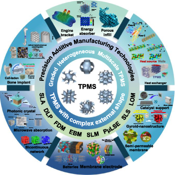
Figure 1. Overview of this review of TPMS porous structures. Reproduced with permission from [68]. Copyright 2020, the Author(s), CC BY-NC-ND 4.0 [36]. Copyright 2017, the Authors, CC BY 4.0 [69]. Copyright 2020, IEEE [70]. Copyright 2020, the Authors, CC BY 4.0 [71]. Copyright 2021, the Authors, CC BY 4.0 [60]. Copyright 2019, Elsevier [72]. Copyright 2019, Royal Society of Chemistry [73]. Copyright 2018, Elsevier [74]. Copyright 2019, Elsevier [75]. Copyright 2018, Royal Society of Chemistry [64]. Copyright 2017, American Chemical Society [66]. Copyright 2021, Elsevier [67]. Copyright 2015, WILEY-VCH Verlag GmbH & Co. KGaA, Weinheim [56]. Copyright 2017, American Chemical Society [76]. Copyright 2019, Acta Materialia Inc. CC BY-NC-ND 4.0 [77]. Copyright 2020, Acta Materialia Inc.
Download figure:
Standard image High-resolution imageAlthough TPMS is an interesting research hot spot in different areas, the advantages of TPMS are not fully utilized. Most of the current research only focused on the performances or applications of one discipline. The current research directions are chaotic and scattered. Interdisciplinary studies of TPMS are needed to further promote the widespread applications of TPMS. For example, TPMS can be designed with complex shapes, graded porosity, and multiscale pores by CAD algorithms. However, most of the current adopted TPMS no matter in thermology or chemistry are still standard TPMS structures with uniform porosity and simple shapes. In addition, as the intermediate link between TPMS design and applications, the manufacturing methods still need to be improved. Complex TPMS structures with external shapes and internal architectures bring great challenges to the current additive manufacturing technologies. Although some new manufacturing technologies are currently proposed, the calculation efficiency and accuracy in the path planning process need further to be improved. More fabrication restrictions should be taken into consideration in the design process to further improve the manufacturing quality. Based on the above-discussed background, a review from TPMS design, manufacturing to applications will be presented. The structure of this work is presented in figure 1. Specifically, the multiscale design methods including geometry design and performance control will be discussed in sections 2 and 3. Then, current precise additive manufacturing technologies will be summarized in section 4. Based on that, diverse interesting applications will be introduced according to different disciplines in section 5. Finally, the conclusions and outlooks will be presented.
2. TPMS design strategies
As the first important factor of TPMS porous structures, appropriate 3D models will be generated by the design strategies. Actually, the geometry features, such as porosity or volume specific surface areas have great influences on the performances. Hence, the geometry design is the basis for further performance control in different disciplines. Different from the conventional foam of lattice structures, TPMS can be designed with more complex features to mimic natural porous structures. In this work, the multiscale design methods of TPMS include the graded TPMS, heterogeneous TPMS, internal multiscale pores, and TPMS with complex external shapes.
2.1. Geometry design by CAD algorithms
Compared with other kinds of porous structures, TPMS owns three notable features. Firstly, TPMS belongs to the implicit surface. Hence, the whole geometry can be completely expressed via algebraic equations, which can be simplified as  , in which
  is a constant. Based on that, TPMS is also regarded as isosurface. Secondly, TPMS is periodic in three independent directions. The distribution range and period can be conveniently controlled by the function parameters. At last, TPMS is also characterized as minimal surface, which means the mean curvature of TPMS is zero. The smooth surfaces are similar to the soap bubbles and leaves in nature [78]. More interestingly, as shown in figures 2(a) and (b), some structures found in butterfly wings [79] and weevil exoskeletons [80] are very similar to TPMS, which indicates TPMS has promising bionic application potential.

Figure 2. Natural TPMS-like porous structures. (a) Wings of a butterfly. Reproduced with permission from [79]. Copyright 2016, the Authors, CC BY-NC 4.0. (b) Weevil exoskeletons. Reproduced with permission from [80]. Copyright 2018, WILEY-VCH Verlag GmbH & Co. KGaA, Weinheim.
Download figure:
Standard image High-resolution imageThere are two main methods to express TPMS. According to the Enneper–Weierstrass parametrical representation approach, TPMS can be precisely calculated as [8]:
in which  ,
,  is a complex variable,
  is the Bonnet angle and Re represents the real part of a complex variable.
 is the Weierstrass function of different kinds of TPMS units. For example, the Weierstrass function of D, P, and G surfaces can be expressed as:
And the Bonnet angle for D, P and G surfaces are 0, 90° and 38.0147°, respectively [8]. However, only a few kinds of TPMS units can be generated by this approach. The Weierstrass function have been found for a few minimal surfaces for now. As the other mathematical method, TPMS can be generated by [81]:
in which  is the amplitude,
  is the period factor,
  is the function phase. Based on that, common TPMS units can be described as shown in table 1.
Table 1. Mathematical expressions of different TPMS units.
| Unit name | Mathematical expressions | 3D models |
|---|---|---|
| P |

|

|
| G |


|

|
| D |


|

|
| I-WP |

![$ + \cos \left( {{\omega _y}y} \right)\cos \left( {{\omega _z}z} \right) + \cos \left( {{\omega _z}z} \right)\cos \left( {{\omega _x}x} \right)]$](https://content.cld.iop.org/journals/2631-7990/4/2/022001/revision3/ijemac5be6ieqn16.gif)
![$ - \left[\cos \left( {2{\omega _x}x} \right) + \cos \left( {2{\omega _y}y} \right) + \cos \left( {2{\omega _z}z} \right) \right] = C$](https://content.cld.iop.org/journals/2631-7990/4/2/022001/revision3/ijemac5be6ieqn17.gif)
|

|
| F-RD |


![$ + \cos \left( {2{\omega _y}y} \right)\cos \left( {2{\omega _z}z} \right)]$](https://content.cld.iop.org/journals/2631-7990/4/2/022001/revision3/ijemac5be6ieqn20.gif)

|

|
| I2-Y** |

![$ + \sin \left( {{\omega _x}x} \right)\sin \left( {2{\omega _y}y} \right)\cos \left( {{\omega _z}z} \right) + \cos \left( {{\omega _x}x} \right)\sin \left( {{\omega _y}y} \right)\sin \left( {2{\omega _z}z} \right)]$](https://content.cld.iop.org/journals/2631-7990/4/2/022001/revision3/ijemac5be6ieqn23.gif)


|

|
Due to the implicit characteristic, both the geometries and performances are depending on the mentioned simple implicit functions. Similar to parametric surfaces in the CAD domain, most of the current TPMS need to be discretized as mesh models for visualization or additive manufacturing. In virtue of the famous Marching cube algorithm [82], the smooth TPMS surfaces are approximately expressed by numerous triangle facets, as shown in table 1. Apparently, the space is divided by TPMS as two parts which can be expressed as  and
and  . Note that TPMS is a kind of surface without wall thickness. Further materialization operation is needed for generating TPMS porous structures. As shown in figure 3, the sheet TPMS porous structures will be constructed by directly offsetting the TPMS surfaces with constant wall thickness. And the two parts divided by TPMS are defined as network TPMS porous structures.
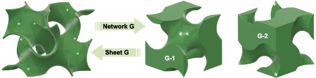
Figure 3. Network and sheet TPMS generation principle.
Download figure:
Standard image High-resolution image2.2. Graded TPMS porous structures
According to the TPMS functions in table 1,  and
and  are two important parameters which have influences on the TPMS period and curvature. For network TPMS porous structures, the volume ratio between two divided parts only depends on the curvature parameter
  . Hence, the period parameter
  and curvature parameter
  can be defined as different values to generate graded or non-uniform TPMS porous structures. With regard to sheet TPMS, the wall thickness should also be taken into consideration. For sheet TPMS with different
  and wall thickness combinations, the relative densities may still be equal. In our previous work, the parameter
  and
and  are designed with graded values to generate graded surfaces [9]. As shown in figure 4(a), although the surface is drastically altered by adjusting period parameter
  values, the continuity and smoothness of TPMS can still be retained. For network TPMS in figure 4(b), relative densities can be directly controlled by setting different parameter
  [83]. Moreover, the graded sheet TPMS porous structures with different offset wall thicknesses can be acquired as presented in figure 4(c).
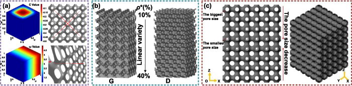
Figure 4. Graded TPMS porous structures. (a) Adjusting  and
and  to generate graded surfaces. Reproduced with permission from [9]. Copyright 2018, Elsevier. (b) Adjusting
  to generate graded network TPMS. Reproduced with permission from [83]. Copyright 2018, Elsevier. (c) Adjusting wall thickness to generate graded sheet TPMS. Reproduced with permission from [84]. Copyright 2020, the Authors, CC BY-NC-ND 4.0.
Download figure:
Standard image High-resolution imageIn fact, the graded porous structures are widely existing in nature. For example, the porosities of human bones are gradually changed from cancellous bones to cortical bones. Hence, it is an effective approach to mimic natural architectures via graded porous structures. Note that, the graded porous structures can also be generated by conventional lattice or foam structures. Compared with these solutions, the graded TPMS porous structures own two obvious advantages. Firstly, the graded porosities can be precisely controlled via TPMS functions. For example, the parameter  can be defined as a function which is related to coordinates. The porosities of graded TPMS presented in figure 4 are linearly changed. More complex graded porous structures with non-linear changing porosities can be more conveniently constructed by TPMS. Secondly, due to the function controllable characteristics, the internal surfaces are still smooth with ideal connectivity and continuity. The curvature, period, and wall thickness can be adjusted in different degrees. More design freedom can be provided by TPMS to generate graded porous structures.
2.3. Heterogeneous TPMS porous structures
In material science, in order to give full play to the advantages of different materials, most applied engineering structures are composed of diverse kinds of materials. Similarly, any TPMS units are not perfect with all advantages. As the basic performance index of TPMS porous structures, the relative density or porosity, and volume specific surface areas are widely utilized in engineering to evaluate the porous structures. However, for TPMS units mentioned in table 1, both ideal performances cannot be acquired at the same time by one kind of TPMS unit. Hence, the heterogeneous TPMS is proposed to fulfill more complex application demands [85]. Note that, the material of heterogeneous TPMS can be the same. The TPMS units are regarded as different components to generate heterogeneous porous structures. Fortunately, each component TPMS unit can be expressed by a mathematical expression. Hence, the mission of generating heterogeneous porous structures is to choose appropriate TPMS units in different regions. As shown in figure 5(a), the G and D structures can be utilized together [86]. The surfaces of heterogeneous TPMS porous structures are still smooth. With regard to the transition between different regions, the unit weight can be changed according to linear or sigmoid rules. Based on this design freedom, any TPMS units can be selected in required regions for special applications as presented in figure 5(b) [87]. For example, a dense cortical shell with a porous cancellous interior, and dense cortical layers on the outer surfaces with a thin cancellous structure inside can be designed as shown in figure 5(c) [15]. The merits of heterogeneous TPMS and comparisons between heterogeneous and graded TPMS can be illustrated in figure 5(d) [88]. The porosities of distinct regions of natural structures are different. The graded P can be utilized to generate porous structures with similar porosity distributions to the natural architectures. However, in order to further mimic the complex functions, more factors should be taken into considerations. Although the porosity and permeability of P structures are higher, Young's moduli of D are larger than that of P structures under the same relative density [88]. Hence, the advantages of distinct units should be utilized in different regions.
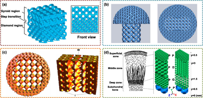
Figure 5. Heterogeneous TPMS porous structures. (a) Heterogeneous TPMS from D to G structures. Reproduced with permission from [86]. Copyright 2018, the Authors, CC BY 4.0. (b) Heterogeneous TPMS with different units in different regions. Reproduced with permission from [87]. Copyright 2015, Korean Society for Precision Engineering and Springer-Verlag Berlin Heidelberg. (c) Bio-mimetic heterogeneous TPMS. Reproduced with permission from [15]. Copyright 2014, Elsevier. (d) Comparisons between graded and heterogeneous TPMS. Reproduced with permission from [88]. Copyright 2018, American Chemical Society.
Download figure:
Standard image High-resolution imageSimilar to the merits of graded TPMS, the internal surfaces of heterogeneous TPMS are still smooth. However, due to the topology differences, the transition regions may be drastically changed. Reasonable transition rules are necessary to improve continuity. Compared with graded TPMS, more design freedom is provided by heterogeneous TPMS.
2.4. Multiscale TPMS porous structures
Regardless of graded TPMS or heterogeneous TPMS porous structures, the scales of the pores are basically the same in previous discussions. Nevertheless, most natural porous structures are hierarchical with multiscale pores. The porosity and volume specific surface areas can be further improved by multiscale porous structures. Generally, the porous structures can be classified as microporous structures with pore diameter less than 2 nm, mesoporous structures with pore diameter greater than 2 nm and less than 50 nm, and macroporous structures with pore diameter greater than 50 nm. It is a great challenge to efficiently generate multiscale porous structures by CAD algorithms.
Although TPMS can be accurately expressed by implicit functions, it is still difficult to design multiscale TPMS via only one function. The pore sizes of graded TPMS are different but not crossing scales. The surfaces will be dramatically changed if the microporous and macroporous structures appear in the graded TPMS porous structures at the same time. According to classical CAD algorithms, Boolean operations are effective approaches to merge multiscale porous structures together. However, there are disadvantages of the conventional 3D Boolean operations to generate multiscale porous structures. Firstly, the Boolean operation is very time-consuming and error-prone. As mentioned before, the TPMS surfaces are extracted as mesh models for geometry processing in most cases. In order to improve construction accuracy, numerous discrete facets are needed. The intricate porous structures with complex pores further increase the burden of calculation. The computer memory may be consumed before the calculation is completed. Even if the calculation memory is large enough, numerous errors may exist after Boolean operations between each discrete facet. Moreover, the calculation results after Boolean operations may be incorrect for multiscale TPMS. Some tiny parts of TPMS may be broken or separated from the main parts. And it will be impossible to fabricate these TPMS with separated parts by additive manufacturing. Although some attempts [19] have been made to accelerate and improve the calculation process, these disadvantages of 3D Boolean operations are still unavoidable.
In our previous work, a new strategy was proposed to generate multiscale TPMS porous structures [22]. The 3D calculation is simplified as 2D operations to improve the calculation efficiency. The solid areas of TPMS are meshed for extracting TPMS with smaller pores. And the layered extracted TPMS areas are alternately regarded as solid or pore areas. Hence, some areas separated by pores will be reconnected again by the TPMS areas of the next level. Four-level TPMS will be enough to generate multiscale TPMS porous structures with pores of three scales, which are shown in figure 6(a). The generated layered areas of multiscale TPMS porous structures can be directly handled by additive manufacturing, saving the time-consuming slicing process. Differently, Li et al developed an efficient merging method to construct multiscale TPMS porous structures [21]. As shown in figure 6(b), TPMS with pores of different scales are directly merged together. In order to reduce the sharp boundaries, Allen–Cahn equation was utilized to generate smooth surfaces. The stress concentration can be obviously reduced by the proposed optimization methods. Yet, the proposed methods are implemented based on the network TPMS rather than the sheet TPMS. Ding et al made use of the Boolean operations to acquire multiscale TPMS porous structures [20] as shown in figure 6(c). The pores of the next level are iteratively subtracted from the solid parts of the current level. Due to the disadvantages of the 3D Boolean operations discussed before, only simple structures with fewer scales can be efficiently generated by this method.
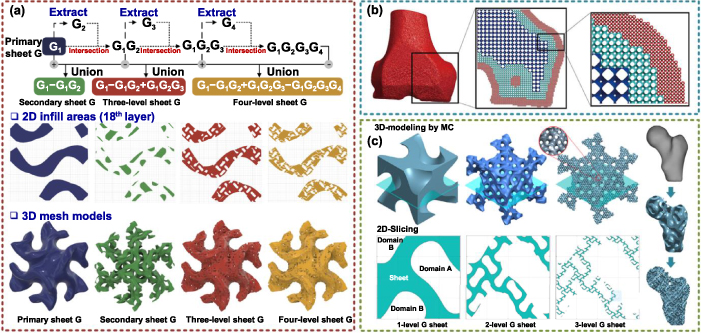
Figure 6. Multiscale TPMS porous structures. (a) Multiscale TPMS generation based on fractal sheet TPMS structures. Reproduced with permission from [22]. Copyright 2019, Elsevier. (b) Merging TPMS units with multiscale pores to construct multiscale TPMS. Reproduced with permission from [21]. Copyright 2021, Elsevier. (c) Multiscale TPMS generation based on iterative Boolean operations. Reproduced with permission from [20]. Copyright 2021, CIRP.
Download figure:
Standard image High-resolution imageIn summary, the computational complexity of the multiscale structures geometrically grows with the increase of the scales. Different from the graded and heterogeneous TPMS, there is no effective method to describe multiscale TPMS via implicit functions. The 3D Boolean operations can only be adopted for simple structures. More reliable design strategies of multiscale TPMS porous structures are eager to be developed.
2.5. TPMS porous structures with complex external shapes
In previous discussions, the internal porous features are designed with diverse strategies according to different requirements. The external shapes of most of these structures are simple geometries, such as cubes or spheres. In fact, porous structures with different freeform surface shapes are required in most practical applications. For example, the tissue engineering scaffolds or implants need to be designed as same as the defect parts as possible. For a long time, most of the current CAD algorithms of porous structures only pay attention to the internal pores, ignoring cooperation and unification with the shape design methods. In order to design a porous scaffold with a bone shape, four steps are needed by conventional methods. Firstly, a 3D model should be reconstructed according to the bone features. Secondly, the maximum and minimum sizes in three directions need to be calculated to acquire the envelope region. Thirdly, porous structures, such as TPMS, should be generated in the envelope region. Lastly, the intersection parts between the 3D bone model and porous structures in the envelope region are obtained by Boolean operations. After these processes, ideal porous structures with both required internal porous architectures and external shapes are acquired. However, there are three obvious shortcomings of this method. First of all, the calculation efficiency and accuracy of 3D Boolean operations are unreliable for designing complex porous structures as discussed before. Numerous model errors may occur after mesh tailoring and reorganization calculations. Moreover, the porous structures which are outside of the target structures and inside of the envelope region are useless for the final results. The calculation memory and time cost for these structures are wasteful. Lastly and most importantly, the relative positions between external shapes and internal pores are hardly controlled, especially for non-uniform porous structures. Slight relative position differences will result in a completely different pore distribution result. Based on this background, some attempts have been made to solve this problem.
In order to improve the efficiency of Boolean operations, the scalar field is adopted to describe the distances between the target model and porous structures in the envelope region [89]. The design results are shown in figure 7(a). However, the process of constructing a scalar field will also cost a lot of time. The intrinsical drawbacks of Boolean operations are not avoided. Inspired by the meshing process of the finite element method, Yoo directly mapped TPMS units to the target 3D models [81]. The original target model was voxelized. Afterward, in virtue of the shape function, each TPMS unit is mapped from the parametric domain to the space domain, as shown in figure 7(b). The conventional Boolean operation is completely avoided by this method. The porosities of TPMS structures can be conveniently controlled by adjusting the density of the voxelization. Though promising, the shapes of TPMS unit will be changed in the mapping process. Some original smooth characteristics of TPMS may be destroyed. In addition, both the voxelization and mapping processes are implemented after acquiring the target 3D model. If the target model needs to be modified, all mentioned processes will be repeated, which is time-consuming for some applications, such as medical implants.
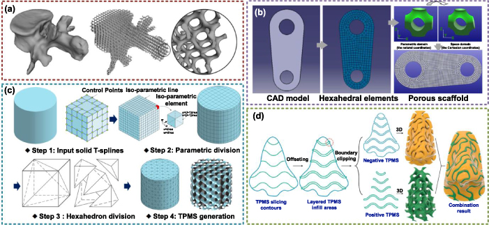
Figure 7. Design methods for TPMS porous structures with complex external shapes. (a) Three-dimensional Boolean operation design approach. Reproduced with permission from [89]. Copyright 2017, Springer International Publishing Switzerland. (b) Shape function mapping method. Reproduced with permission from [81]. Copyright 2011, Korean Society for Precision Engineering and Springer-Verlag Berlin Heidelberg. (c) Porous TPMS design based on solid T-splines. Reproduced with permission from [9]. Copyright 2018, Elsevier. (d) Two-dimensional design strategy for TPMS with freeform shapes. Reproduced with permission from [22]. Copyright 2019, Elsevier.
Download figure:
Standard image High-resolution imageIn our previous work, the solid T-spline was adopted to design TPMS porous structures with freeform external shapes as shown in figure 7(c) [9]. T-spline is an effective tool to design freeform surfaces. As a kind of parametric surface, the parametric space is regular and easy to be divided. Hence, the solid T-spline can be conveniently divided into numerous cubes for TPMS extraction. Moreover, the control points can be used to save the TPMS parameters to generate graded or heterogeneous TPMS porous structures. With help of the local refinement algorithms of the T-spline, local geometry or porosity features can be finetuned or interactively modified. Therefore, the design freedom can be greatly improved by this method. Similar methods were also introduced based on B-spline [23]. However, the efficiency of the whole process is not ideal as expected. For porous structures whose design efficiency is more important than the iterative design demand, the 2D design strategy is a better choice [22]. As shown in figure 7(d), the external shapes will be sliced as layered areas. Then, the 2D TPMS contours are extracted in the meshes inside of external shape layers. After offsetting and 2D Boolean operations, the layered TPMS areas with freeform shapes can also be acquired as layered areas, which can be directly fabricated via additive manufacturing.
3. Performance control of TPMS
The performances of TPMS porous structures are the research focus in recent years. The goal of geometry design is generating TPMS with similar features to outstanding natural porous architectures. Based on that, the performance control strategies aim to construct TPMS porous structures which can be successfully applied in engineering. The mechanical performances, thermal performances, optic performances, or multiphysics coupling performances need to be controlled for different applications. Two important aspects need to be discussed for performance control in this section. Firstly, the basic performances will be analyzed according to diverse disciplines. Moreover, some novel methods will be introduced to further optimize the TPMS performances.
3.1. Mechanical performances
Among performances of different disciplines, the research on mechanical performances is the most. Regardless of whether the TPMS porous structures are used as scaffolds, energy absorbers, or heat exchangers, basic mechanical performances are required to keep the structures stable and reliable. The elastic modulus, Poisson's ratio, and anisotropic properties are the basic mechanical property indexes which should be payed close attention [90]. The elastic and anisotropic properties of TPMS are evaluated by Every's diagram as shown in figure 8(a). The porous structures can be regarded as a special kind of composite material with material phase and air phase. Hence, the Hashin–Shtrikman upper bound is effective to evaluate the mechanical properties of TPMS. Compared with hollow lattices, the bulk modulus properties of TPMS are much closer to the theoretical limit, as shown in figure 8(b). For porous structures, relative density is regarded as the most important influence factor on the elastic modulus. The scaling laws are utilized in most research to describe the relationship between relative density and elastic modulus or plateau stress [36]. According to the finite element analysis (FEA) and compression tests, the changing laws of modulus with relative density can be fitted to smooth curves [37, 38, 40, 45, 91]. The geometry features of network TPMS can be completely expressed by the relative density. However, as discussed before, the sheet TPMS with different parameter combinations may own the same relative density. Hence, the mechanical properties of sheet TPMS cannot be accurately described by the relative density. The parameter influences on the elastic modulus and anisotropic properties are systematically analyzed in our previous work [92]. According to the developed design map, the elastic modulus and anisotropic properties can be controlled at the same time.
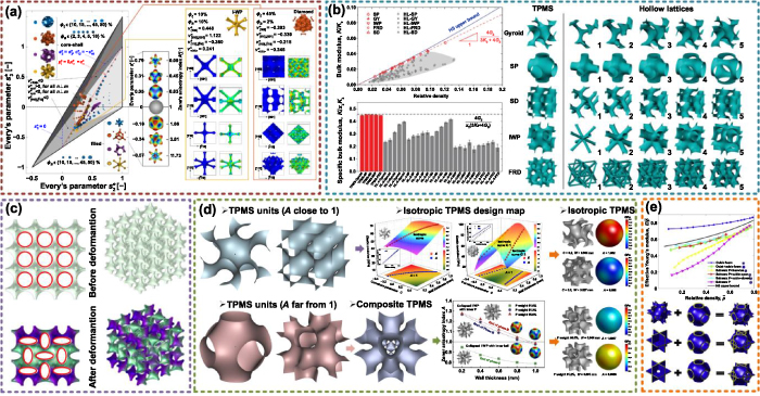
Figure 8. Basic mechanical properties of TPMS. (a) Elastic and anisotropic properties of TPMS. Reproduced with permission from [29]. Copyright 2019, Acta Materialia Inc. (b) TPMS modulus close to the theoretical bound. Reproduced with permission from [93]. Copyright 2021, the Royal Society of Chemistry. (c) TPMS with negative Poisson's ratio. Reproduced with permission from [30]. Copyright 2020, the Authors, CC BY-NC-ND 4.0. (d) Isotropic TPMS design methods. Reproduced with permission from [92]. Copyright 2021, the Authors, CC BY 4.0. (e) Anisotropic property control method based on hybrid TPMS. Reproduced with permission from [94]. Copyright 2019, the Authors, CC BY-NC-ND 4.0.
Download figure:
Standard image High-resolution imagePoisson's ratio is utilized to evaluate the ratio between material transverse and vertical deformation, which is greater than 0 in most cases. However, Poisson's ratio of TPMS can be designed as negative with special parameter combinations. As presented in figure 8(c), the structure shrinks in the transverse direction under compression. The auxetic behavior of the constructed TPMS is dominated by buckling instability. Due to the special auxetic behavior, the Poisson's ratio can be controlled to meet diverse special demands for sensors or energy absorbers. The mechanical performances of most of the porous structures are distinct in different directions, which means the porous structures are anisotropic. For some special applications, the anisotropic behavior is even considered as harmful. For example, the energy absorbers need bear loading from different directions. The weak directions may be prematurely broken or invalid before total failure. It is an effective way to adjust the TPMS parameters to control the anisotropic properties and even to generate isotropic TPMS [32]. However, the porosities of isotropic TPMS may be too high or too low which cannot be accurately fabricated. In our previous work, the TPMS units with complementary anisotropic properties were utilized to generate composite TPMS with close isotropic properties, as shown in figure 8(d) [92]. Then, the wall thickness of composite TPMS is adjusted to generate accurate isotropic TPMS. Note that the composite TPMS is similar to the heterogeneous TPMS. The functions of different units are combined with different weights. Hence, the internal surfaces are still smooth. Differently, the hybrid TPMS is constructed by directly combining two TPMS units as presented in figure 8(e) [94]. Although the structures can also be designed with isotropic properties, the original smooth features of TPMS are destroyed.
Besides the basic mechanical property indexes, the compression behaviors of TPMS have also been systematically studied [95–103]. Due to the porous internal structures, much energy can be directly absorbed. Four regions including the nonlinear stage, linear elastic stage, elastic plastic stage, and post-yield region can be observed from the TPMS compression stress–strain curves [104]. Compared with network TPMS, the energy absorption capability and efficiency of sheet TPMS are superior. Lu et al discussed the differences between G and P structures under compression, as shown in figure 9(a) [105]. The TPMS structures are fabricated by digital light processing (DLP) technology with ZnO powder. The G structures can bear much more deformation than the P structures during the compression tests. Moreover, Maskery et al studied the compressive failure modes as presented in figure 9(b) [43]. The cell size has important influences on the failure mechanism. Low-strain structural failure can be avoided by the smaller size. More interestingly, more energy can be absorbed by TPMS after heat treating. As mentioned in section 2.2, the graded structures can be designed by TPMS. Yang et al introduced the energy absorption capability of graded TPMS. The energy absorption capability decreases with the increase of the cell size as shown in figure 9(c) [106]. In addition, the graded P structures can absorb more energy than the uniform P structures [107]. However, the energy absorbability of graded and uniform G is very similar. Long plastic plateaux is important for energy absorbing. Maskery discussed the compressive deformation behaviors of G, D, and P [36]. High stiffness and strength can be supplied by P structures. D and G structures are better choices for undergoing high strain before failure as shown in figure 9(d). Similarly, compared with P or G, the energy absorption of IWP and Neovius structures is higher [35, 103].
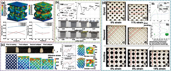
Figure 9. Mechanical behaviors under compression. (a) Comparisons between G and P structures under compression. Reproduced with permission from [105]. Copyright 2021, Elsevier Ltd and Techna Group S.r.l. (b) Compressive failure modes and energy absorption of G structures. Reproduced with permission from [43]. Copyright 2017, the Authors. CC BY 4.0. (c) The deformation and collapse behaviors of graded D structures. Reproduced with permission from [106]. Copyright 2021, Elsevier. (d) Compressive deformation behaviors of G, D, and P. Reproduced with permission from [36]. Copyright 2017, the Authors, CC BY 4.0.
Download figure:
Standard image High-resolution imageIn order to further illustrate the merits of TPMS, the mechanical performances of the sheet, network TPMS, and classical lattice, such as Kelvin, octet-truss and Gibson–Ashby are analyzed and compared. Sheet TPMS structures exhibited a near stretching-dominated deformation behavior, while skeleton TPMS showed a bending-dominated behavior [108]. Furthermore, among these structures, the sheet TPMS structures own superior performances [37]. As discussed before, TPMS can be regarded as a composite material with solid and air. Some interesting attempts have also been made to generate interpenetrating phase composite TPMS by replacing the air phase with other kinds of material to further improve the mechanical performances [91, 109–114]. Speirs et al studied the fatigue behaviors of TPMS scaffolds which are fabricated by selective laser melting (SLM) with NiTi shape memory alloy [39]. Compared with the octahedron unit, superior fatigue resistance can be acquired by TPMS due to the smooth surfaces without nodal points. In addition, the fracture toughness of TPMS has also been studied in recent research [115, 116]. Interestingly, the bandgaps can be acquired by G structures [41]. The bandgap width can be further adjusted by changing the cell size and volume fraction. Khan et al studied the viscoelastic behaviors of TPMS under both time and frequency domains [117]. Experimental results showed that the IWP structures own superior behaviors under uniaxial loading, and shear and bulk responses of P structures are the highest. Moreover, based on the merits of TPMS, some novel porous structures are developed for better performances. Cao et al designed P-lattice by generating lattice struts along the smooth surfaces [118]. Compared with traditional lattices, superior mechanical properties and higher energy absorption characteristics can be obtained. Maskery and Ashcroft developed a new gyroid-based honeycomb by changing the honey wall shape according to the G surfaces [119]. Novel deformation and post-yield stiffening under in-plane loading can be obtained.
Although there are numerous studies of the TPMS mechanical properties, the geometries of the discussed TPMS are basically simple. The actual performances of TPMS with freeform shapes under complex application environments need more research attention. Moreover, different kinds of TPMS units own diverse advantages. How to choose suitable TPMS units in different applications is an important question. Considering diverse requirements in multidisciplinary and multifunctional applications, a trade-off will be needed.
3.2. Thermal (heat transfer) performances
Dealing with the extra heat during the operation process is an important problem no matter for microchips in computers or large-scale machinery and equipment. The porous structures are widely applied as heat exchangers for a long time. The internal heat exchange areas can be greatly improved by the complicated architectures with high porosity. Due to these merits, most of the current heat exchangers are designed based on stochastic metal foams or parameterized lattice structures. Theoretically, the interconnected and smooth pores of TPMS are more ideal candidates for heat changing. The controllable geometries and porosity properties as discussed before are precious merits for further improving heat transfer efficiency. Compared with traditional porous heat exchangers, few TPMS heat exchangers are adopted in actual engineering. But the thermal performance advantages of TPMS have been studied and proved by current limited research.
Kaur and Singh discussed the flow and thermal transport characteristics of TPMS [58]. The TKD structure which is the commercially open-cell foam was utilized to compare the performances with TPMS. The heat transfer distribution of P, G, and TKD from different views can be seen in figure 10(a). The average heat transfer coefficients of G are 1.07 times higher than TKD. In addition, heat can be dissipated twice by G structures compared with TKD structures under the same temperature differences. Wang utilized the computational fluid dynamics (CFD) simulations to evaluate the TPMS performances [120]. The 3D models of commercially random foams are reconstructed via micro-computed tomography (CT) to compare the property differences. The temperature distributions of commercial foams and F-RD structures are shown in figure 10(b). According to the experimental results, the F-RD structures can obtain 103% higher thermal conductivity than the stochastic foams with the same porosity. The better connectivity along the heat transfer direction is the main reason for the higher thermal conductivity. Qureshi et al made use of TPMS as the heat transfer structures for the phase change materials in thermal energy storage [57]. The TPMS structures are set inside of the phase change materials. Hence, after heating, the solid materials will become liquid. The liquid fraction at 30 s can be seen in figure 10(c). Compared with the Kelvin structures, more liquid can be found in TPMS structures. The I-WP structure owns the best performances in pure conduction than G, P, and Kelvin structures. While the P structure owns the best performances in natural conduction than G, I-WP, and Kelvin structures. Hassan et al adopted the TPMS as advanced heat sinks for electronic components [121]. The heat transfer coefficient and interface surface areas are two important factors for heat transfer. The temperature contours of network G and network D are the lowest and highest, respectively. And the temperature contours of sheet G and network D are basically the same. The surface areas of network G and D are the same. And the surface areas of sheet G are twice of network G. Hence, network D showed the highest convection heat transfer coefficient according to the CFD results.
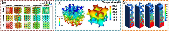
Figure 10. Thermal performances of TPMS porous structures. (a) Heat transfer distribution of P, G, and TKD. Reproduced with permission from [58]. Copyright 2021, Taylor & Francis Group. (b) Temperature distributions of commercial foam and F-RD. Reproduced with permission from [120]. Copyright 2021, Elsevier. (c) The liquid fraction at 30 s after heat transferring by porous structures. Reproduced with permission from [57]. Copyright 2021, Elsevier.
Download figure:
Standard image High-resolution imageIn addition, Al-Ketan studied the heat transfer performances of graded TPMS [59]. The temperature contours and velocity streamlines of uniform and graded D from different directions were discussed. The porosities of uniform and graded structures are the same. However, the surface areas of uniform TPMS are 22% higher than graded TPMS. Experimental results showed that the porosity grading structure results in a significant pressure drop of 27.6%, while the convective heat transfer drop is less at 15.7%. A suitable porosity distribution design is an effective way to control the heat transfer performances. But the flow performances of graded structures with the same porosity of uniform structures cannot be improved. Mirabolghasemi et al discussed the thermal conductivity of TPMS based on the homogenization method, and periodic representative volume elements [122]. For G, D, and P structures with curvature parameter  , similar homogenized thermal conductivities can be obtained. And the effective thermal conductivity of the P structure decreases with
  from 0 to 0.8. Moreover, the thermal conductivity of TPMS is primarily a function of the relative density [123]. And thermal conductivity is inversely proportional to the surface area to volume ratio. However, for convective heat transfer, thermal performance is typically proportional to surface areas. Besides the heat conduction in the solid phase, the radiative heat conductivity was also studied [124]. Both conductive contribution and radiative contribution should be taken into consideration for evaluating the effective thermal conductivity. And the radiative contribution is a linear function of the radiation/conduction ratio.
In summary, due to the high-volume specific surface areas and smooth porous structures, TPMS structures are ideal candidates for heat transfer applications. The thermal performances of TPMS in some special applications are even superior to conventional porous structures, such as foams or lattices. Similar to mechanical performances, the thermal performances of TPMS can be conveniently controlled by the TPMS unit type, relative density, and structural parameters. However, current research is still not enough for further complex applications. The thermal performances of graded, heterogeneous, and multiscale TPMS which are designed by the mentioned methods in section 2 are not thoroughly studied. These intersecting questions need more research attention in the future.
3.3. Permeability (mass transfer) performances
As discussed before, TPMS structures are highly interconnected with non-tortuous pores which are suitable for mass transfer. Due to this advantage, TPMS porous structures can be applied as porous electrodes of fuel cells and batteries, porous filters, and tissue engineering scaffolds [125, 126]. Permeability is an important index to evaluate the fluid flow conduct performances. All these porous features, such as porosity, tortuosity, pore size, and interconnectivity have great impacts on permeability [127]. Recently, as the theoretical basis for engineering applications, some interesting studies have been carried out.
Montazerian et al discussed the pore shape and porosity influences on the longitudinal and radial permeability as shown in figure 11(a) [128]. The permeability of unidirectional flows was analyzed in most research. However, for some special applications such as tissue engineering, the cells radially grow in these porous scaffolds. Hence, it is also necessary to evaluate the longitudinal permeability. According to the experimental results, the permeability of TPMS, especially I-WP structures, is higher than lattice structures in longitudinal directions. The radial permeability is half of the longitudinal permeability in the cylindrical scaffolds. The relationship between porosity and permeability can be described by the power law as well as the Kozeny–Carman models. Zhianmanesh et al analyzed the fluid permeability of graded TPMS porous structures as presented in figure 11(b) [129]. For uniform TPMS structures, P and G structures own the highest permeability values. With regard to radially graded TPMS, the sensitivity of permeability to the peripheral porosity was found to be almost twice as the central porosity. Moreover, the graded porosity influences on the permeability are depending on the topology of porous structures. Higher permeability of P structures can be obtained by the higher central porosity. For I-WP and G structures, permeability can be improved by the deviation from uniform porosity. However, for the IJ*-P2 structure, the highest permeability is obtained by the uniform porosity. Montazerian et al studied the fluid permeability of TPMS for constructing porous scaffolds [130]. The TPMS scaffolds manufactured by fused deposition modeling and corresponding permeability results are shown in figure 11(c). Compared with uniform scaffolds, higher permeability can be obtained by radially gradient pore distributions. The permeability values of P structures are lower than D or G structures. Ma et al discussed the mass transport performances of G structures for designing bone-mimicking scaffolds [131]. Almost no turbulence can be found in the G structures. The fluid pressure and velocity of G structures are shown in figure 11(d). Higher permeability can be obtained by a larger pore diameter. The permeability of G scaffolds can even be adjusted similar to the original bones. In order to predict the permeability of TPMS, Asbai-Ghoudan further developed an analytical model according to the desired architecture, pore size, and porosity [132]. The differences between the prediction and actual permeability are less than 5%. The flow paths of FKS, G, and P structures are shown in figure 11(e). In most cases, the permeability of the P structure is the highest. However, for porous structures with 50% porosity, the G structure owns higher permeability. In order to evaluate the permeability of porous structures, Darcy's flow is utilized in most cases. Santos et al further calculated the permeability of TPMS based on Forchheimer's law, which was proved as a good mathematical tool as Darcy's law expansion [133]. According to the experimental results, TPMS structures can achieve good permeability values while remaining less porous. Although the permeability can be improved by higher porosity, the mechanical performances of TPMS will be weakened. Hence, a reasonable trade-off between mechanical properties and permeability needs to be made according to diverse application requirements [134–136]. TPMS structures with higher permeability under the same relative density may be a better choice for multidisciplinary applications.

Figure 11. Permeability performances of TPMS porous structures. (a) Longitudinal and radial permeability of TPMS porous structures. Reproduced with permission from [128]. Copyright 2017, Elsevier. (b) Fluid permeability of graded TPMS porous structures. Reproduced with permission from [129]. Copyright 2019, American Chemical Society. (c) Polydimethylsiloxane TPMS scaffolds and corresponding permeability results. Reproduced with permission from [130]. Copyright 2019, Acta Materialia Inc. (d) The pressure and velocity of G structures. Reproduced with permission from [131]. Copyright 2019, Elsevier. (e) The flow paths of FKS, G, and P structures. Reproduced with permission from [132]. Copyright 2021, the Authors, CC BY-NC-ND 4.0.
Download figure:
Standard image High-resolution imageIn general, the permeability study of TPMS is still a research hotspot in recent years [137–140]. The permeability can be obviously improved by TPMS structures. Appropriate permeability control is important for mass transfer applications, such as tissue engineering scaffolds or bone implants. Precise prediction and evaluation of the TPMS permeability is still a challenge. Similar to the research status of other performances, most of the current research only focused on the standard TPMS with cube shape. Although some attempts have been made to discuss the permeability of graded TPMS, the influence mechanism of the porosity distribution, heterogeneous TPMS, and multiscale TPMS need more research attention.
3.4. Performance optimization
Although the TPMS structures own many advantages in mechanical properties, heat, and mass transfer performances, it is still of great significance to further optimize the TPMS performances. As a kind of porous structure, the mass of TPMS is much lighter than the solid structure under the same envelop volume. However, the mechanical strength will be inevitably weakened by the porous architectures. Actually, in practice, the performances of solid structures are excessive. Replacing the solid structures as porous structures is an effective way to achieve the lightweight purpose. The material, energy, and fabrication time can be obviously saved by these lightweight structures. Note that, a trade-off between the mechanical performances and the structure weight always exists. As discussed in our previous research, the art of the lightweight structure design for 3D printing is to find a balance between the material-consuming and physical performances [141], which means that suitable pores need to be designed in ideal positions for acquiring the best strength-to-weight ratio. Over past decades, with the help of additive manufacturing, lattice and foam structures were widely used as lightweight structures [142, 143]. Recently, some novel attempts have been made to design lightweight structures based on the porous TPMS for seeking a better strength-to-weight ratio.
Li et al proposed a density-variable shape modeling method for interior structure optimization [144]. The stress distributions of complex models were analyzed according to the cross-section method. The relationship between the curvature parameter of the G structure and the relative density was fitted with implicit functions. Afterward, the suitable parameter was utilized in different regions for generating graded internal TPMS porous structures as shown in figure 12(a). With help of this method, the strength of the complex structures can be increased, meanwhile, the use of materials can be minimized. Hu et al further developed a lightweight TPMS generation framework based on the proposed strength-to-weight optimization method [145]. According to the given conditions including the external loads and gravity, the input model will be divided on the basis of the stress field. The porosity values of different divided regions are changed by the non-uniform TPMS. In order to ensure the smoothness of the transition regions, the compactly supported radial basis function interpolation method was utilized. Furthermore, the TPMS parameters were iteratively optimized to generate lightweight structures with more stress distribution, which is presented in figure 12(b). Compared with other existing methods, lighter structures with smooth features can be acquired under the same external loads.
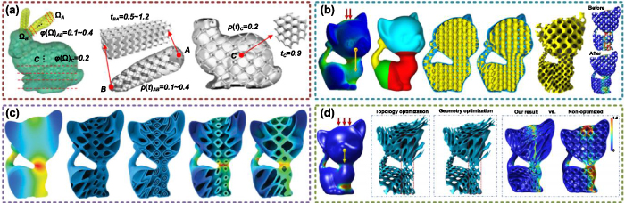
Figure 12. Lightweight optimization based on the TPMS porous structures. (a) Lightweight TPMS design based on the density-variable shape modeling method. Reproduced with permission from [144]. Copyright 2015, Springer-Verlag London. (b) Lightweight TPMS generation based on the strength-to-weight optimization method. Reproduced with permission from [145]. Copyright 2019, Springer-Verlag GmbH Germany, part of Springer Nature. (c) Lightweight structure design by internal TPMS channel. Reproduced with permission from [146]. Copyright 2020, IEEE. (d) Lightweight TPMS structure design according to TPMS functions. Reproduced with permission from [69]. Copyright 2020, IEEE.
Download figure:
Standard image High-resolution imageDifferent from the above methods to generate interior lightweight TPMS for additive manufacturing, Yan et al proposed a lightweight design strategy by constructing internal TPMS channels for material injection [146]. As discussed before, the internal smooth surfaces and excellent permeability of TPMS are very suitable for injection. Similar to other strategies, the stress field calculation was utilized as the first step to generate graded TPMS channels with different period parameters and uniform width. The channel widths and TPMS period were iteratively optimized in an interleaving manner according to the corresponding FEA results. In virtue of the optimized channels, the lightweight TPMS structures can be obtained as shown in figure 12(c). Compared with the lightweight structures designed by lattices or foams, larger loads can be afforded. In the conventional FEA process, the meshing operation is very time-consuming, especially for porous structures. Hu et al further developed a lightweight optimization method directly based on the TPMS functions [69]. The period and wall thickness were defined as topological and geometrical parameters and iteratively optimized as shown in figure 12(d). In order to bear the same external loads, the same input structure can be optimized by the strength-to-weight optimization method [145] and the implicit function optimization method [69] to 28% and 25%, respectively. The optimized structures will also be comparable or stronger than the TPMS channel with injection [146]. Up to now, there are still many attempts for generating lightweight structures. It is significant to maximize the actual application performances with the least materials. Due to the outstanding performances and controllable geometries, TPMS structures are expected to become the candidate of next-generation lightweight structures for wider engineering applications.
Although the graded TPMS with diverse porosity distributions can be conveniently generated by the methods mentioned in section 2.2, how to select suitable porosities in different regions is a critical problem. Topology optimization is an effective method in the structure optimization domain. According to the design domain, loads and constraints, suitable material density distributions can be obtained. For solid material, the density of the structures in each calculation element can only be 0 or 1. Hence, the solid isotropic microstructures with penalization method was developed for avoiding elements with intermediate density. However, the relative density of TPMS porous structures can be directly adjusted from 0 to 1. Recently, more and more interesting research is based on topology optimization and TPMS porous structures.
Li et al introduced an effective TPMS optimization method based on the homogenization and topology optimization methods [147]. The relationship between curvature parameter and relative density was fitted as scaling laws. In virtue of the numerical homogenization method, the elastic scaling laws of TPMS can also be obtained. Each constant of the stiffness matrix can be calculated as a function of relative density. After the topology optimization process, the corresponding relative density distributions can be acquired to generate graded TPMS. Considering the additive manufacturing direction, some porous TPMS structures can be further removed as shown in figure 13(a). Under the same volume ratio, the deformation of optimized TPMS is 1/9 of that of uniform TPMS structure. Moreover, Ren et al designed the multi-TPMS by topology optimization method [148]. As presented in figure 13(b), different TPMS units were utilized together in multi-TPMS, which is also named as heterogeneous TPMS in section 2.3. An improved sigmoid function was used to increase the smoothness of the transition regions. Under the same density distribution, compared with gradient P the equivalent stiffness is increased by 17.6%, compared with gradient IWP the equivalent stiffness is increased by 90.4%. Li et al further proposed a kind of extended TPMS for topology optimization [149]. The performances can be predicted by the offline parametric homogenization method with high accuracy. Optimized extended TPMS can be more efficiently generated as shown in figure 13(c). The density distribution results from topology optimization can be used in different ways to generate graded TPMS. Panesar et al compared the different design strategies [150] as illustrated in figure 13(d). According to the performance requirements and manufacturing restrictions, the graded TPMS which is designed by mapping the relative density onto the greyscale density solution of topology optimization is the most desirable solution. More importantly, the topology optimization method is also adoptable for requirements of other disciplines. Li et al optimized the TPMS relative density distributions of heat-sink [151]. Under the same volume ratio, the maximum temperature of uniform TPMS can be decreased from 66.1 °C to 57.4 °C by the graded TPMS structures. The heat transfer performances can be further improved by a larger density range, as shown in figure 13(e). Moreover, the topology optimization method can also be utilized to design bandgap structures [152], as shown in figure 13(f). In brief, topology optimization is an outstanding tool to provide guidance for generating graded or heterogeneous TPMS porous structures. The requirements of multidiscipline can be summarized as different optimization targets for seeking ideal relative density distributions. However, the iterative optimization process is relatively time-consuming. More efficient topology optimization methods are still research hotspots in the current study. Some two-dimensional density results are not precise enough for solving problems of actual engineering. Actually, in practice, there are more restrictions need to be considered in the optimization process, which will further increase the burden of calculation. All these problems need more research attention to generate ideal TPMS models with suitable geometries and performances.

Figure 13. Topology optimization of TPMS porous structures. (a) TPMS optimization based on homogenization and topology optimization methods. Reproduced with permission from [147]. Copyright 2018, Elsevier. (b) Multi-TPMS optimization based on topology optimization. Reproduced with permission from [148]. Copyright 2021, the Authors, CC BY-NC-ND 4.0. (c) Topology optimization of extended TPMS structures. Reproduced with permission from [149]. Copyright 2020, Elsevier. (d) Comparisons of different TPMS design strategies. Reproduced with permission from [150]. Copyright 2017, the Authors. (e) Heat-sink design by topology optimization [151]. Copyright 2019, ASME. (f) Bandgap structure design based on topology optimization method. Reproduced with permission from [152]. Copyright 2020, Springer-Verlag London Ltd, part of Springer Nature.
Download figure:
Standard image High-resolution image4. Additive manufacturing methods of TPMS
The manufacturing quality has great influences on the actual performances of TPMS porous structures. Due to the complex topology and intricated porous architectures, most of the current TPMS structures are fabricated by additive manufacturing methods. According to the material required by actual applications, diverse forming principles can be selected. Although the TPMS structures can be conveniently fabricated by additive manufacturing layer by layer, the porous features, and complex topology are still great challenges to the precision and efficiency of current manufacturing methods. Related work about the additive manufacturing methods for TPMS will be reviewed in this section.
4.1. Selective laser melting (SLM)
The SLM technology is widely utilized to fabricate metal structures in engineering. The powder material is melted by the laser layer by layer. The powder which is not melted after one layer can be used as support for the next layer. However, for structures with numerous hanging surfaces, such as TPMS, enough support structures are still needed. Considering the manufacturing process of SLM, both the sizes of laser spot and powder have great influences on the manufacturing quality.
Yan et al discussed the manufacturability of TPMS using the SLM technology with 316 l stainless steel powder [153]. According to the experimental results, all the unit sizes ranging from 2 to 8 mm can be fabricated by SLM without defects and additional support structures. However, there are a lot of bonded particles on the surfaces as shown in figure 14(a). The surface roughness is increased by these bonded particles. Fan et al fabricated graded TPMS by SLM with Ti6Al4V powders [95]. As shown in figure 14(b), semi-melted powders also exist on the surfaces. Compared with structures with uniform wall thickness, less support can be supplied by the thinner walls of graded structures. The defects gradually decreased along the gradient direction. Hence, the thickness errors of graded structures are greater. For porous TPMS structures, the largest deviations will be found at the upper inner walls of pores [99]. In order to further improve the surface roughness, the sand-blasted method is effective to reduce the influences of stair steps and overhang or bonded particles, as presented in figure 14(c). With regard to the fabrication material, diverse metal materials can be selected for different purposes. Yavari et al fabricated TPMS implants with titanium powder [154]. The laser paths were optimized without overlapping contours as shown in figure 14(d). Ma et al compared the SLM fabricated TPMS and the designed models by CT images [155]. The pore size values of fabricated TPMS were all less than that of the designed models as shown in figure 14(e). The manufactured errors ranged from 46 to 80 μm.
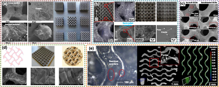
Figure 14. Porous TPMS structures fabricated by SLM. (a) Manufacturability of TPMS porous structures. Reproduced with permission from [153]. Copyright 2012, Elsevier. (b) Graded TPMS fabrication with Ti6Al4V powders. Reproduced with permission from [95]. Copyright 2021, Elsevier. (c) Comparisons between as-built and sand-blasted TPMS structures. Reproduced with permission from [99]. Copyright 2019, Acta Materialia Inc. (d) Porous TPMS fabricated with titanium powder. Reproduced with permission from [154]. Copyright 2020, the Authors, CC BY 4.0. (e) Comparisons between fabricated and designed TPMS structures. Reproduced with permission from [155]. Copyright 2020, the Authors, CC BY-NC-ND 4.0.
Download figure:
Standard image High-resolution image4.2. Selective laser sintering (SLS)
Similar to the SLM manufacturing method, the laser is utilized for SLS technology as the input energy for fabricating structures layer by layer. Differently, the powder material is sintered together as products. Hence, more materials can be selected for SLS, such as metal, ceramics, and plastics. Moreover, the fabrication quality is also greatly affected by the powder. Al-Ketan et al fabricated TPMS structures by SLS with gas atomized maraging steel fine powder [37].
Some powder was stuck on the printed structures as shown in figure 15(a). And the layer step can also be observed along the printing direction. Abou-Ali et al fabricated TPMS structures by SLS with polyamide nylon powder [156]. The actual relative densities of printed structures were close to the designed values. Ideal printing quality and manufacturability can be obtained as presented in figure 15(b). Elmadih et al also utilized nylon-12 powder for fabricating TPMS by SLS technology [41]. As shown in figure 15(c), compared with the originally designed model, the maximum cell size and volume fraction deviation are 1.8% and 10%, respectively. And the maximum differences of the minimum feature were 3.2% of the nominal values. The differences between measured and nominal values can be controlled smaller than the laser spot size, which means that the fabricated TPMS structures can be used for vibration isolation in the discussed applications. Maskery et al made use of the EOS polyamide PA2200, which is also based on the nylon 12 to manufacture TPMS porous structures [36]. As presented in figure 15(d), the average volume fraction of printed structures was 0.294  0.007, which was very close to the designed fraction of 0.3. The abovementioned SLM and SLS technologies can be defined as the laser powder bed fusion method, which is widely utilized to fabricate complex porous structures such as TPMS. More fabrication attempts can be found in current research [157–159].
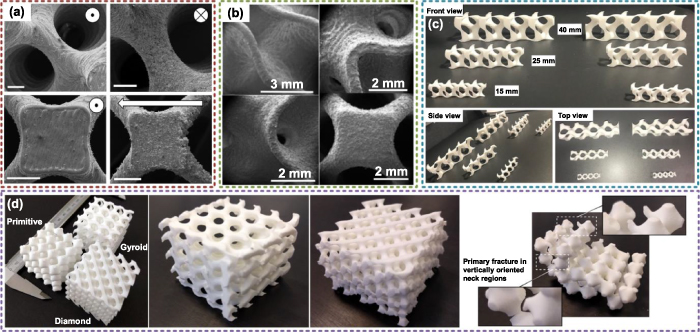
Figure 15. Porous TPMS structures fabricated by SLS. (a) Metal TPMS structures. (The scale bar is 1 mm). Reproduced with permission from [37]. Copyright 2017, Elsevier. (b) Nylon TPMS structures. Reproduced with permission from [156]. Copyright 2020, the Authors, CC BY 4.0. (c) Nylon-12 TPMS. Reproduced with permission from [41]. Copyright 2018, the Authors, CC BY 4.0. (d) EOS polyamide PA2200 TPMS. Reproduced with permission from [36]. Copyright 2017, the Authors, CC BY 4.0.
Download figure:
Standard image High-resolution image4.3. Stereo lithography appearance (SLA)
As another precise additive manufacturing technology, SLA is utilized to cure photosensitive liquid material layer by layer with ultraviolet or other special light. The designed models can be fabricated with high accuracy by controlling the light spot size, which is also regarded as the printing resolution. However, due to the limitation of the fabrication principle, only a small amount of material with photosensitive properties can be utilized by SLA. Generally, the manufacturing precision of SLA is much higher than the above SLM or SLS methods. Based on that, more and more TPMS structures are fabricated by SLA in recent research.
Zhang et al fabricated ceramic TPMS based on the SLA technology [115]. The Al2O3 material was merged with photosensitive liquid for curing reaction. The lateral resolution and z-resolution were 40 and 25  m, respectively. As shown in figure 16(a), the TPMS structures can be directly manufactured with high accuracy. Macroscopic pores or cracks cannot be found on the printed walls. UIIah et al fabricated calcium phosphate TPMS structures for bone scaffolds [51]. The 10Mg–CaP and Mg, Zn–CaP powders were merged with photosensitive resin, dispersing agent, and photoinitiator. The wall thicknesses and pore sizes of printed structures which are shown in figure 16(b) were 300 and 500
  m, respectively. The grain boundaries can be clearly observed. Elomaa et al made use of the poly(
 -caprolactone) (PCL) to manufacture TPMS scaffolds [160]. The resin for SLA was composed of PCL macromer, Irgacure 369 photoinitiator, inhibitor, and dye. Due to the special material preparing process, no obvious shrinkage was found in the final structures. As shown in figure 16(c), the average porosity measured by μCT was 70.5
  0.8%, which is very close to the designed 70% porosity. The fabricated pore sizes were 400–500 μm. Yu et al fabricated graded TPMS structures with commercial resin [107] as presented in figure 16(d). The wall thickness accuracy was higher than 94%. The maximum weight deviation was 2.89%. With regard to the porosity, the maximum deviation was 1.41% from the designed model. Recently, numerous commercial SLA equipment and resin material have been developed for fabricating complex structures. Good accuracy and surface quality can be acceptable for most engineering requirements.

Figure 16. Porous TPMS structures fabricated by SLA. (a) Ceramic TPMS structures. Reproduced with permission from [115]. Copyright 2019, Elsevier Ltd. (b) Calcium phosphate TPMS structures. Reproduced with permission from [51]. Copyright 2021, Elsevier. (c) Poly( -caprolactone) TPMS structures. Reproduced with permission from [160]. Copyright 2011, Acta Materialia Inc. (d) Resin TPMS structures. Reproduced with permission from [107]. Copyright 2019, the Authors, CC BY-NC-ND 4.0.
Download figure:
Standard image High-resolution image4.4. Digital light processing (DLP)
The DLP technology is developed based on the basic fabrication principle of SLA by curing photosensitive liquid material. Differently, the liquid material is curved point by point by SLA to generate the whole structures. Yet, each sliced layer of structures is directly cured by DLP in each projection step. Apparently, the manufacturing efficiency can be greatly improved by DLP. However, limited by the resolution of the projection equipment, the DLP fabrication sizes of the structures are basically smaller than SLA. Currently, DLP is also an ideal choice to precisely fabricate TPMS porous structures.
Saed et al fabricated the poly L-lactic acid (PLLA) TPMS structures by DLP technology [161]. A commercial DLP 3D printer was used with 1024 × 768 pixels. And the size of the pixel was 77 × 77  m. The fabrication principle and structure features are presented in figure 17(a). The fabrication parameters, especially the exposure time and dye concentration have great influences on the manufacturing quality and corresponding mechanical performances. After numerous tests and optimization, suitable parameters can be found to fabricate TPMS with minimal deviation and the best mechanical performances. Similar to SLA technology, ceramic structures can also be precisely fabricated by the DLP method. The silicone powder, photopolymer, and photoabsorber were merged for DLP [66]. As shown in figure 17(b), the fabrication steps can be clearly observed. But no cracks can be found in the printed structures. The manufacturing quality of the ceramic TPMS can meet the demands of microwave absorbers. Li et al fabricated polyethylene (glycol) diacrylate (PEGDA) TPMS structures by DLP technology [26] as presented in figure 17(c). A theoretical prediction method was developed to choose the suitable parameter combinations for manufacturing. Based on this method, the TPMS structures can be precisely fabricated with PEGDA and other photocurable material by the DLP method. Due to the high viscosity, most of the existing
  -tricalcium phosphate (
 -TCP) slurries are not suitable for DLP. Li et al utilized the DLP technology to fabricate
  -TCP/58S TPMS scaffolds [162]. Different from normal DLP printers, they printed TPMS with a light source placed above the tank, as shown in figure 17(d). Hence, the light can directly reach the photosensitive material. Compared with the structures fabricated by DLP, the volume will further be reduced after sintering. Based on the proposed methods, TPMS structures can be precisely fabricated as bone scaffolds. In general, due to the precise manufacturing principle and optical control system, DLP is an outstanding solution to fabricating TPMS porous structures.
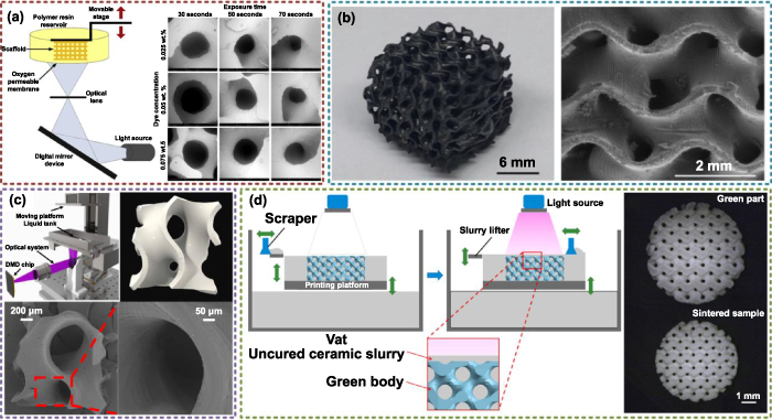
Figure 17. Porous TPMS structures fabricated by DLP. (a) Poly L-lactic acid (PLLA) TPMS structures. Reproduced with permission from [161]. Copyright 2020, the Society of Manufacturing Engineers. (b) SiOC ceramic TPMS structures. Reproduced with permission from [66]. Copyright 2021, Elsevier. (c) Polyethylene (glycol) diacrylate (PEGDA) TPMS structures. Reproduced with permission from [26]. Copyright 2020, Elsevier B.V. (d)  -tricalcium phosphate/58S TPMS structures. Reproduced with permission from [162]. Copyright 2021, Elsevier B.V.
Download figure:
Standard image High-resolution image4.5. Fused deposition modeling (FDM)
The FDM technology is widely adopted for desktop 3D printers. As a method of material extrusion technology, the precision of FDM is much lower than SLA or SLM. Especially for complex structures like TPMS, many support structures are needed for hanging surfaces. And the surface quality will be further destroyed after removing support structures. Hence, considering the geometry structures, FDM is actually not an ideal choice for fabricating TPMS porous structures. However, for some materials, such as polylactic acid (PLA) and acrylonitrile butadiene styrene (ABS), FDM technology is an effective way for manufacturing. Alizadeh-Osgouei et al fabricated PLA TPMS scaffolds as presented in figure 18(a) via FDM technology [163]. All the designed pores are open with good connectivity. But the strut sizes are smaller than the designed values. Due to the shock and clogged nozzle, bubbles will appear during the manufacturing process. Hence, some defects can be found on the printed surfaces. Diez-Escudero et al also fabricated PLA TPMS structures for bone scaffolds [164]. As shown in figure 18(b), the surfaces of printed TPMS are much rougher than structures manufactured by SLA. But the basic geometry features and pore sizes can still be obtained. For some applications which are not sensitive to the manufacturing quality, the FDM technology can also meet the demands of applications. Khan et al fabricated ABS TPMS porous structures via the FDM method [45]. In order to improve the surface quality, the dissolvable support material was utilized. The manufacturing paths of infill and support areas were shown in figure 18(c). The layered areas are infilled line by line. Due to the complex shapes of the layered areas, the printing paths cannot always fill the areas. Hence, air gaps can be found in the printed structures. Although the support structures were removed, some unwanted strands can still be found. The whole printed structures were smaller than the designed models. The manufacturing quality of FDM is not precise enough, but FDM is talented at fabricating structures with fiber-reinforced materials. As shown in figure 18(d), the short carbon fiber-reinforced nylon TPMS structures can be fabricated by FDM for the purpose of lightweight and strength improvement [101]. In summary, FDM is an effective supplementary method to fabricate TPMS structures with required special materials. With help of added support structures and optimized infill paths, the TPMS structures manufactured by FDM can be utilized by engineering applications.

Figure 18. Porous TPMS structures fabricated by FDM. (a) PLA TPMS structures. Reproduced with permission from [163]. Copyright 2020, the Authors, CC BY 4.0. (b) PLA TPMS scaffolds. (The scale bar is 1 mm). Reproduced with permission from [164]. Copyright 2020, the Authors, CC BY 4.0. (c) ABS TPMS structures. Reproduced with permission from [45]. Copyright 2019, Taylor & Francis Group. (d) Short carbon fiber-reinforced nylon TPMS structures. Reproduced with permission from [101]. Copyright 2020, Elsevier B.V.
Download figure:
Standard image High-resolution image4.6. Other special fabrication methods
Besides these widely used AM technologies, there are many special methods to fabricate TPMS porous structures. Cao et al fabricated TPMS structures by projection micro-stereolithography (PμSL) with PEGDA [165]. The manufacturing principle and TPMS results can be seen in figure 19(a). The basic fabrication principle is similar to the SLA and DLP. The layer thickness was only 5  m for each sliced layer. But the ripples and nonuniform thickness still existed on the surfaces. Compared with the designed models, the fabricated thickness was larger, which may be caused by self‐weight in the viscous fluid. Abueidda fabricated TPMS at the micro-scale using the 3D direct laser writing (DLW) based on two-photon polymerization (2PP) [98]. The sample sizes were only a few hundred microns with the smallest features of several microns as shown in figure 19(b). Higher manufacturing precision can be obtained by the proposed methods. Charbonnier et al fabricated TPMS implants by impregnation of wax molds [77]. As illustrated in figure 19(c), both support and build materials were fabricated by the inkjet printer with a layer thickness of 25
  m. The wax mold and the organic adjuvants were removed at 500 °C. And the ceramic structures were sintered at 1200 °C. With help of this method, the deviations between printed implants and the designed models were centered on +1.4
  m. Similarly, Davoodi et al utilized the sacrificial molds to fabricate silicone-based elastomeric TPMS scaffolds [49]. The negative molds for TPMS were fabricated by FDM technology with ABS. Then the silicone-based prepolymer was mixed in the ABS molds. Eventually, the required TPMS structures can be obtained by removing ABS in acetone. As shown in figure 19(d), no ABS residue was observed on the surfaces. Due to the ideal interconnectivity of TPMS, the silicone-based prepolymer can be fully filled in the ABS molds. Hence, no cracks or bubbles were found inside. More similar methods have been adopted in recent research [130, 166].

Figure 19. Porous TPMS structures fabricated by other special methods. (a) TPMS fabricated by P SL. Reproduced with permission from [165]. Copyright 2021, Elsevier Ltd. (b) TPMS fabricated by DLW based on 2PP. Reproduced with permission from [98]. Copyright 2020, Elsevier Ltd. (c) TPMS fabricated by impregnation of wax molds. Reproduced with permission from [77]. Copyright 2020, Acta Materialia Inc. (d) TPMS fabricated by sacrificial molds. Reproduced with permission from [49]. Copyright 2020, Acta Materialia Inc.
Download figure:
Standard image High-resolution image4.7. AM path generation methods of TPMS
The abovementioned methods are the widely applied AM technologies to fabricate TPMS structures. Actually, as the middle step between obtaining CAD models of TPMS and additively manufacturing TPMS, the AM path planning and generation strategies, which are the main tasks of computer-aided manufacturing (CAM) are also important. The layer slicing and infill path generation are two main steps to calculate AM paths. For some AM methods based on layered fabrication, only the sliced layers can be used as the AM paths. Currently, most AM path generation methods are universal strategies proposed for most models with any shape or topology. Although these methods are also effective to generate paths of TPMS, there is still much space to improve the generation quality and efficiency. In order to meet the demands of current CAM software for AM, the designed CAD models need to be converted to triangular mesh models. For complex structures like TPMS, numerous triangular meshes will be needed to improve the model precision, which will also increase the burden of calculation. However, most of the current attention has been payed to the AM methods rather than the AM path generation. Only a little research can be found to optimize the process of generating TPMS paths for AM.
As discussed in section 2.1, the sheet TPMS is constructed by offsetting TPMS surfaces in the 3D space. However, numerous errors may occur after offsetting 3D mesh models. In order to solve that, a systematic method was proposed in our previous work to generate layered infill areas of sheet TPMS [167]. Owing to the mathematical equations of TPMS, the sliced contours can also be precisely described by implicit functions. Hence, the slicing contours can be obtained in 2D meshes. The calculation efficiency can be greatly improved, meanwhile, the space cost by mesh models can also be saved. With regard to the offset problem, the layered infill areas of 3D TPMS can be obtained by offsetting the 2D slicing contours with consideration of the surface curvature. In a word, the 2D layered infill areas of sheet TPMS can be efficiently acquired according to the required input TPMS functions and basic parameters. Zhang et al also proposed a similar strategy to improve the path generation efficiency of porous structures [168]. The generated 2D layered areas can be directly utilized by AM equipment for manufacturing. However, how to optimize the infill paths of TPMS is still a challenge. Most of the layered areas of TPMS are long and narrow. Underfill areas may always appear for generic infill path generation methods. Hence, numerous air gaps will exist on the printed structures, such as the TPMS fabricated by FDM discussed before. This problem needs more research attention in the future.
5. Multidisciplinary applications of TPMS
After geometry design, performance control, and precise additive manufacturing, ideal TPMS products can be acquired for different purposes. Recently, more and more research attention has been payed to the applications of TPMS. Due to the smooth surfaces, highly interconnected pores, TPMS has been successfully applied in multidisciplinary areas. Representative TPMS applications in mechanical, thermal, biological, chemical, acoustic, and optical domains will be reviewed in this section to show the good application potential of TPMS structures.
5.1. Mechanical applications
The basic mechanical performances of TPMS porous structures have been systematically studied. Based on the long linear elastic stage, TPMS structures can be applied as energy absorbers [46, 102] or impact absorbers [169]. Owing to the mechanical vibration bandgaps, TPMS can also be utilized as vibration isolators [41]. Apparently, the weight of TPMS is much smaller than the solid structure under the same envelop volume. In virtue of the optimization methods discussed in section 3.4, TPMS can be used as lightweight structures to save the consumption of materials and energy. In the aerospace or automotive engineering domain, sandwich panels are widely applied. Typical sandwich panels are composed of two face panels with solid structures and internal cores designed by porous structures. Over the past decades, most sandwich panels were designed with lattice cores. Recently, novel sandwich panels are constructed based on the TPMS structures [170]. Desirable bending properties and energy absorption capacity can be acquired by the proposed methods. Alshaer and Harland compared the performances of sandwich panels with honeycomb, lattice, and TPMS cores [171]. Experimental results proved that the highest strength, modulus, and stiffness to weight ratio can be obtained by TPMS cores. Moreover, the TPMS structures can be directly used as functional components in the actual engineering domain. Alkebsi et al made use of TPMS structures as turbine blades [172]. The porosity distribution of TPMS was designed by the topology optimization method. Compared with the original model, the lightweight, stress, and deformation performances were optimized. Wang et al made an attempt to design a joint of a soft robot by TPMS structures [173]. The TPMS parameters can be further adjusted to obtain the linear variable stiffness. Interestingly, Pan et al generate flexure hinges based on TPMS structures [174]. Experimental results showed that the P surface is the most suitable choice for flexure hinges. Compared with traditional leaf flexure hinges, both the compliance and compliance ratio can be greatly improved. In addition to the above examples, there are still many interesting applications of TPMS structures in the mechanical domain.
5.2. Thermal applications
Due to the high-volume specific surface areas, the heat transfer performances of TPMS are outstanding as analyzed in section 3.2. Hence, the TPMS structures are mainly applied as heat exchangers in the thermal domain. Attarzadeh et al made use of D surfaces as the heat exchangers [71]. According to the experimental results, the heat transfer between flowing air and the heat source can be more efficient. The thermal performances of the heat exchanger can be further improved by smaller wall thickness. The supercritical carbon dioxide (CO2) based Brayton cycle is widely adopted in engineering. However, the cycle efficiency and heat transfer performances of current heat exchangers are not ideal as expected. Li made an attempt to use bioinspired TPMS structures as heat exchangers [70]. Compared with printed circuit heat exchangers, only small flow separations can be found in G and D structures, which is owing to the smooth surfaces. Large turbulent kinetic energy production, which is favorable for heat transfer, can be observed in G structures. And the heat transfer rate of TPMS is much higher than printed circuit heat exchangers. Moreover, the heat transfer coefficient of TPMS is 16%–120% higher than printed circuit heat exchangers. However, compared with applications of other domains, the research and applications of TPMS in the thermal domain are at the initial stage. Most of the current applied TPMS heat exchangers are designed with standard shapes and uniform porosities. How to further improve the heat transfer performances of TPMS heat exchangers with minimal volume is an interesting problem that needs more research attention.
5.3. Biological applications
Recently, TPMS structures are widely applied in the biological domain. Actually, the geometry and topology of TPMS are similar to natural structures. Hence, TPMS owns numerous outstanding merits for biological applications. The tissue engineering scaffolds and medical implants are typical biological applications of porous TPMS structures. Different from classical lattice or foam structures, the smooth surfaces of TPMS are suitable for cells to attach and grow. Moreover, the high-volume specific surface areas and the highly interconnected porous architectures can supply enough space for the transport of nutrition and waste. Based on the excellent biological performances and the controllable mechanical, mass transport performances discussed before, TPMS structures have been successfully applied in current biological engineering.
In order to verify the topology advantages of TPMS structures, the structure effects on the cell seeding and culturing were compared between TPMS scaffolds and normal salt-leached scaffolds [175]. With the help of the interconnected pores, the permeability of G structures was ten-fold higher than salt-leached scaffolds. As shown in figure 20(a), large cell populations can be found in the center of the TPMS scaffolds after 5 d of static culture. However, only cell sheets can be observed on the outside of salt-leached scaffolds. Tikhonov et al fabricated TPMS as bone defect filling with PEGDA-based hydrogels and calcium phosphates [176] as shown in figure 20(b). The mechanical properties can be conveniently controlled by adjusting the parameters of TPMS structures. Li et al further discussed the early osteo-integration of Ti6Al4V scaffolds designed by TPMS [177]. The histological results can be seen in figure 20(c). The bone ingrowth can be stimulated by TPMS scaffolds. A stable interface between implants and surrounding bone tissues after 5 weeks' implantation was obtained. Obvious bone formation around all the TPMS porous structures can be found according to the micro-CT results. In order to illustrate the differences with other kinds of porous structures, Hsieh et al compared the performances of lattice and TPMS scaffolds [54] as presented in figure 20(d). More bone growth was observed in the TPMS scaffolds than in the octet truss lattice. In addition, TPMS scaffolds were less prone to fatigue failure than lattice. Barba et al summarized the preferred TPMS pore sizes for different bone stages [76] as presented in figure 20(e). Due to the controllable porosity, TPMS can be designed with diverse pore sizes for bone colonization or bone vascularization. Suitable osseo-integration regions at larger unit cells can be supplied by IWP and Neovius structures. Alabort et al verified the viability of applying TPMS as metallic bones by 3D printing [178]. Ideal osseo-integration can be offered by TPMS structures. As presented in figure 20(f), both cortical and trabecular bones can be mimicked by TPMS with suitable stiffness and strength. Recently, TPMS structures have been applied as scaffolds of different natural bones. Zhu et al utilized TPMS structures as meniscal implants [52]. Compared with the commercial solid meniscal implants, higher magnitude compression and shear stresses on the articular cartilage can be prevented. Some semilunar characteristics can be retained by the TPMS meniscal implants. Pare et al used TPMS calcium phosphate implants for craniofacial bone repair [179]. The new bone formation performances can be greatly improved by the TPMS implants. In general, TPMS structures have been verified as an ideal candidate for biological applications. Outstanding TPMS scaffolds or implants with suitable geometries and performances can be generated to meet the demands of the actual human biological environment.
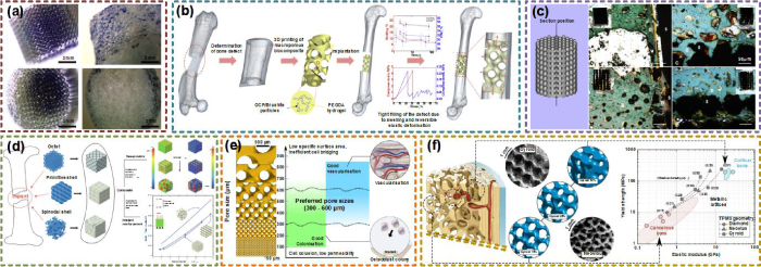
Figure 20. Biological applications of TPMS structures. (a) Combinations between TPMS and salt-leached scaffolds. Reproduced with permission from [175]. Copyright 2010, Acta Materialia Inc. (b) TPMS used as bone defect filling. Reproduced with permission from [176]. Copyright 2020, Elsevier Ltd. (c) Histological results of TPMS scaffolds. Reproduced with permission from [177]. Copyright 2019, the Authors, CC BY-NC-ND 4.0. (d) Comparisons between lattice and TPMS scaffolds. Reproduced with permission from [54]. Copyright 2021, the Authors, CC BY 4.0. (e) Preferred TPMS pore sizes for different bone stages. Reproduced with permission from [76]. Copyright 2019, Acta Materialia Inc. (f) TPMS metallic bone. Reproduced with permission from [178]. Copyright 2019, Acta Materialia Inc.
Download figure:
Standard image High-resolution image5.4. Chemical applications
The interconnected architectures and high-volume specific surface areas of TPMS are also advantages for other applications. For example, in the chemical domain, the efficiency and quality of chemical reactions can be greatly improved if higher chemical contact areas can be supplied. Hence, TPMS structures have great potential for being applied as catalysts or reactors. Some interesting attempts have been made in recent research.
Electrical energy storage systems such as batteries are very important in the current engineering domain. However, how to improve the energy releasing and soring efficiency is still a great challenge. Werner et al designed novel batteries based on the porous TPMS structures [75]. As illustrated in figure 21(a), anode and cathode were generated in different channels of TPMS structures. Stable open circuit voltage, reversible discharge voltage, and capacity can be obtained by the novel TPMS batteries. More importantly, more internal space can be saved by the TPMS. In order to generate the same capacity by the three-layer battery with the same layer dimensions and materials, 4700 times larger space will be taken up. Besides batteries, hydrogen energy is also an important topic in the current chemical and energy domain. Methanol steam reforming is an effective way for hydrogen production. However, the catalyst support has great effects on the catalytic reaction rate and conversion rate of the micro-reforming reactors. Lei et al adopted TPMS structures as the catalyst support [60] as shown in figure 21(b). Compared with the commercial solutions, the hydrogen production performances can be improved by TPMS. In addition, due to the controllability of TPMS from macro scale to micro scale, the flow field and the reaction rate of methanol steam reforming reaction can be controlled. Similarly, Baena-Moreno deigned TPMS microreactors for CO2 methanation [61]. In order to illustrate the advantages of TPMS, the performances were compared with the honeycomb solution as presented in figure 21(c). Under the best situation, 14% improvement can be acquired in CO2 conversion, owing to the improved mass and heat diffusion processes. Sun et al constructed solar vapor generation devices based on TPMS structures [180] as shown in figure 21(d). Compared with other devices, outstanding evaporation performances can be obtained under much lower photothermal component loading. Interestingly, Kobayashi et al made use of TPMS as water absorb films [72] as illustrated in figure 21(e). The smooth surfaces and high-volume specific surface areas can be utilized. Similarly, TPMS structures are also widely applied as the spacers in membrane distillation [181–187]. Note that, most of the current utilized TPMS structures are uniform TPMS structures. In virtue of the design freedom supplied by the design methods discussed in section 2, more interesting applications and more ideal performances can be discussed in the future.
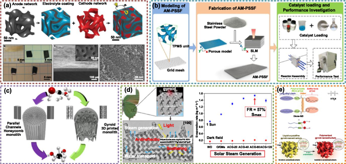
Figure 21. Chemical applications of TPMS structures. (a) TPMS batteries. Reproduced with permission from [75]. Copyright 2018, Royal Society of Chemistry. (b) TPMS catalyst support. Reproduced with permission from [60]. Copyright 2019, Elsevier. (c) TPMS microreactors. Reproduced with permission from [61]. Copyright 2021, American Chemical Society. (d) Solar vapor generation devices based on TPMS. Reproduced with permission from [180]. Copyright 2020, American Chemical Society. (e) TPMS water absorb film. Reproduced with permission from [72]. Copyright 2019, Royal Society of Chemistry.
Download figure:
Standard image High-resolution image5.5. Acoustic and optical applications
The smooth surfaces and sufficient surface areas are utilized in numerous applications in above discussion. Moreover, the highly interconnected architecture is also a merit for wave absorbing. After multiple reflections and refractions, the wave energy can be dissipated as other forms of energy. Feng et al utilized TPMS structures for microwave radiation absorption [66] as presented in figure 22(a). The effective absorption bandwidth and minimum reflection loss were 4.9 GHz and −23.5 dB, respectively. Abueidda et al analyzed the acoustic band gaps of TPMS structures [188] as shown in figure 22(b). Due to the band gaps, the elastic and acoustic waves are forbidden to propagate along any directions. These structures with complete band gaps are defined as phononic crystals. According to the experimental results, one wide complete band gap can be found in P and I-WP structures. Interestingly, Neovius structures own two complete band gaps, which are even wider than I-WP structures. The width of band gaps can be further adjusted by the porosity. Compared with band gaps of other similar structures discussed by other work, wider band gaps can be acquired by TPMS structures. How to find the phononic crystals with complete phononic bandgaps is still a challenge in current research. Hur et al invested the bandgaps of 16 bicontinuous cubic network structures [64]. After experimental tests, six structures including the TPMS structures were verified as ideal phononic crystals with complete bandgaps as presented in figure 22(c). Furthermore, the I-WP structure with a bandgap width of 0.41 was the best choice among these selected structures. Larger phononic bandgaps can even be obtained by higher density contrast between the material components of the structures. Electromagnetic radiation with specific frequencies can be reflected by the photonic crystals [67]. However, for photonic crystals with stable geometries, the frequency of the electromagnetic radiation which can be reflected is also unchangeable. Pouya et al designed the photonic crystal based on the TPMS structures [67] as shown in figure 22(d). More interestingly, the frequency can be tuned by compression loads. Hence, the TPMS tunable photonic crystals can be utilized to meet the demands of complex application environment. Dolan et al also adopted TPMS to generate the optical metamaterials [189] as presented in figure 22(e). Linear dichroism can be found in the G structures. According to these interesting works, TPMS structures own great potential in photonic and phononic metamaterials. Similar to the research status of other applications of TPMS, the actual performances of photonic or phononic metamaterials designed by graded or heterogeneous TPMS need more research attention in the future.
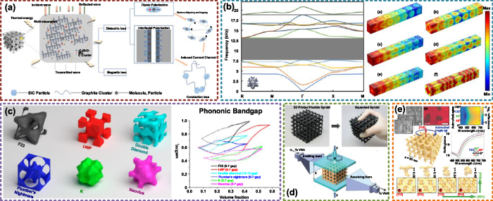
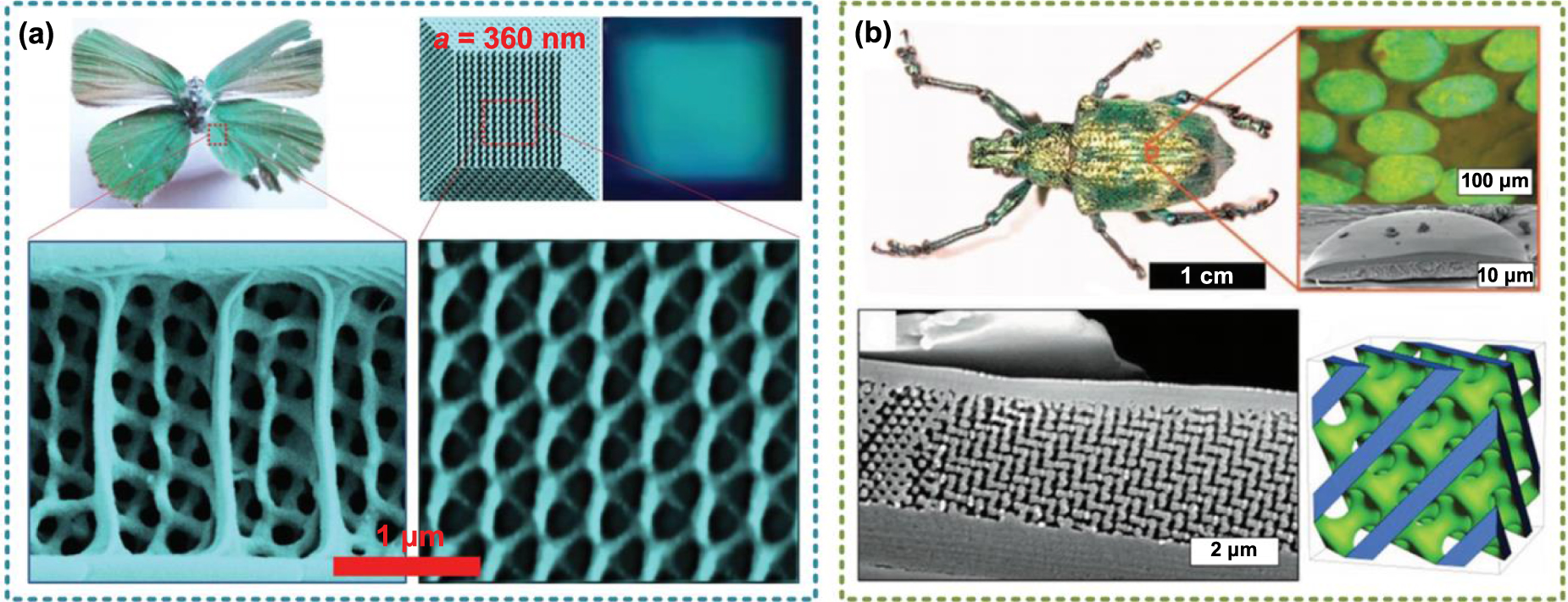
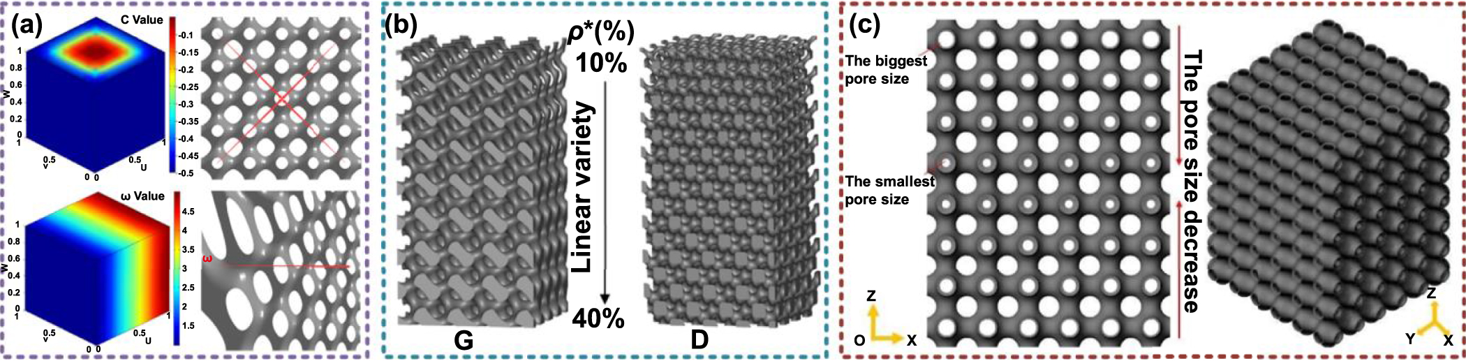
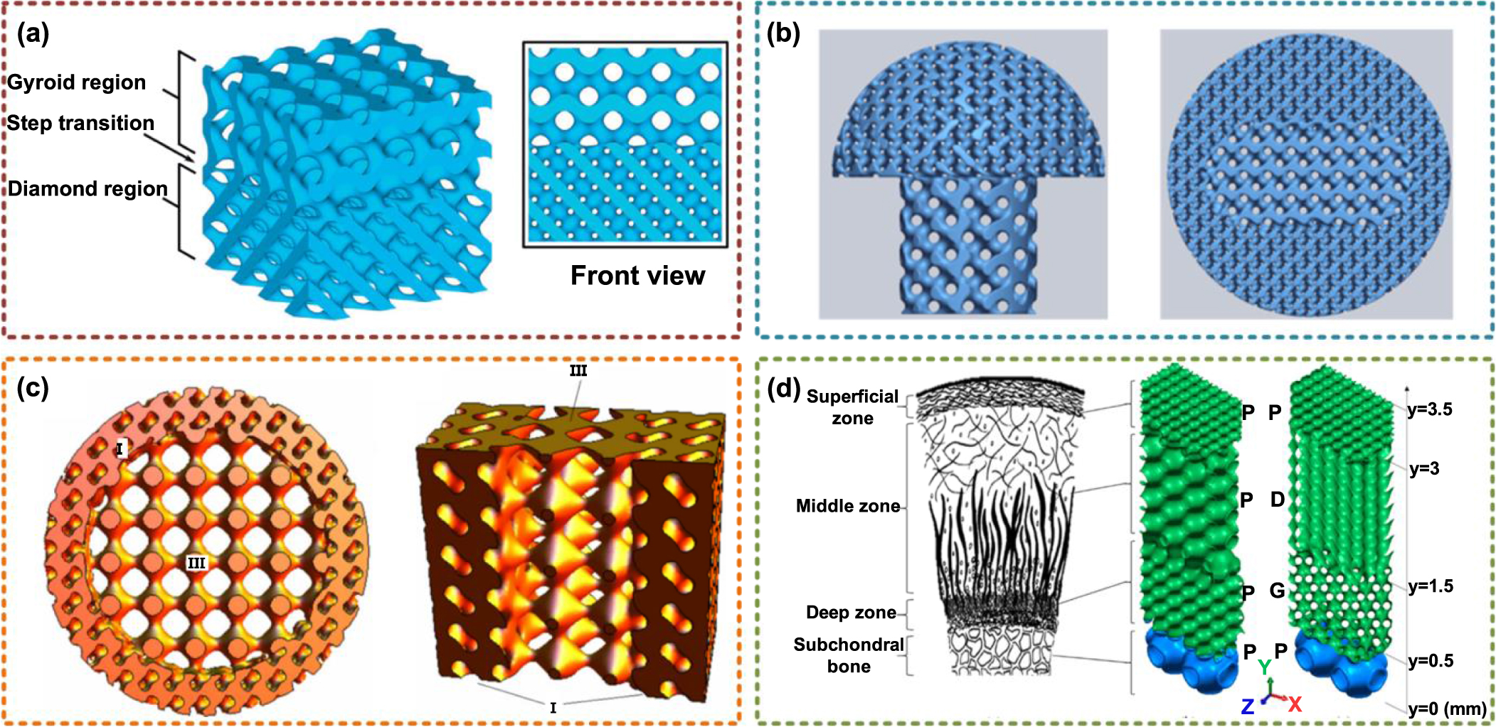
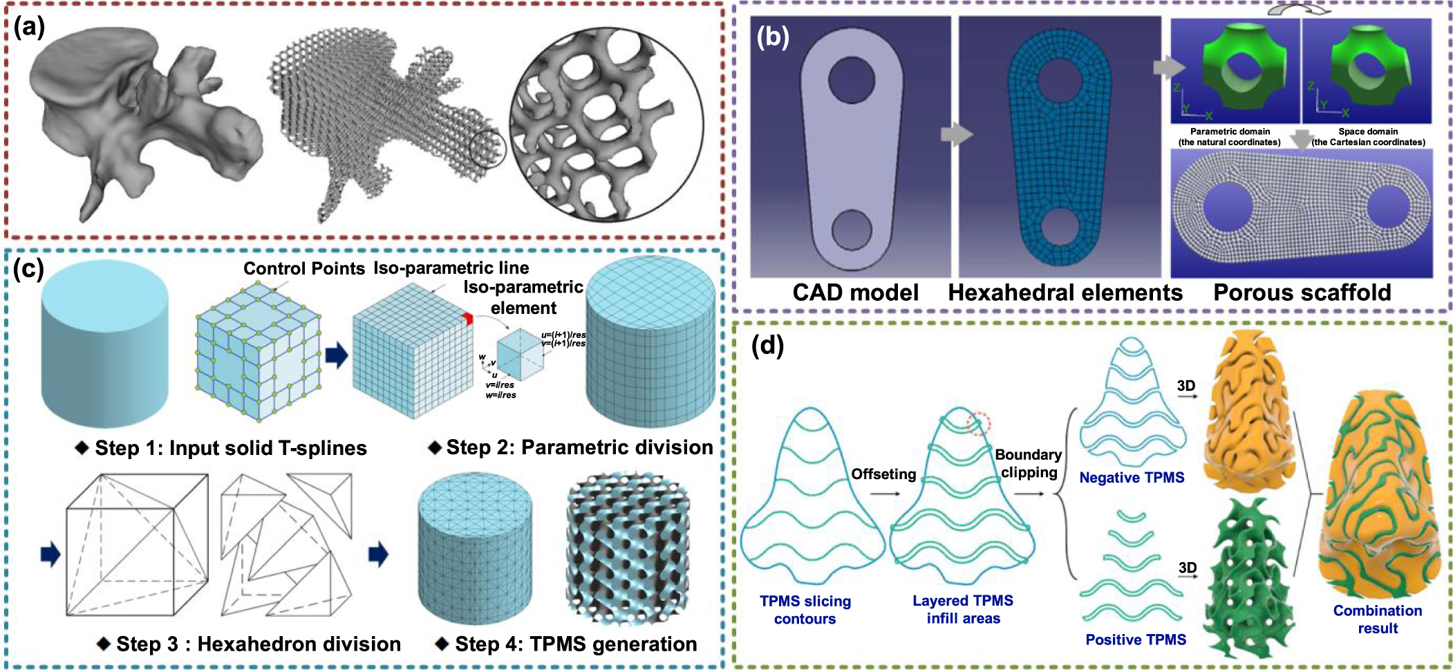
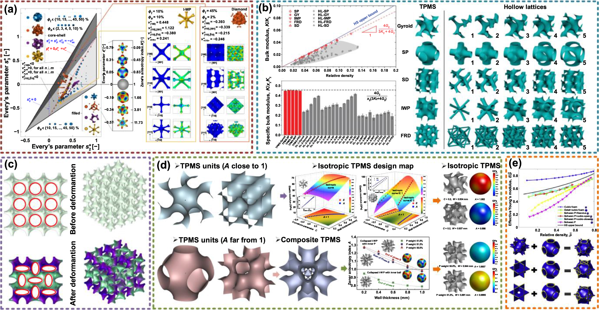
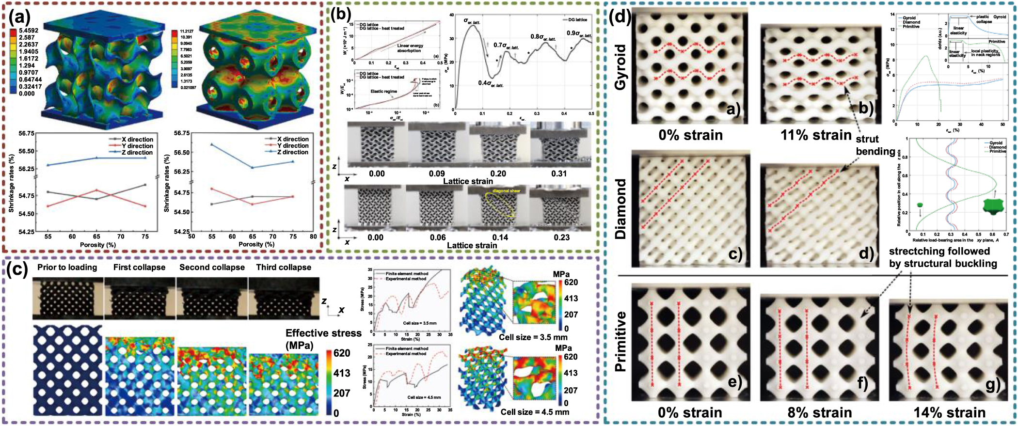
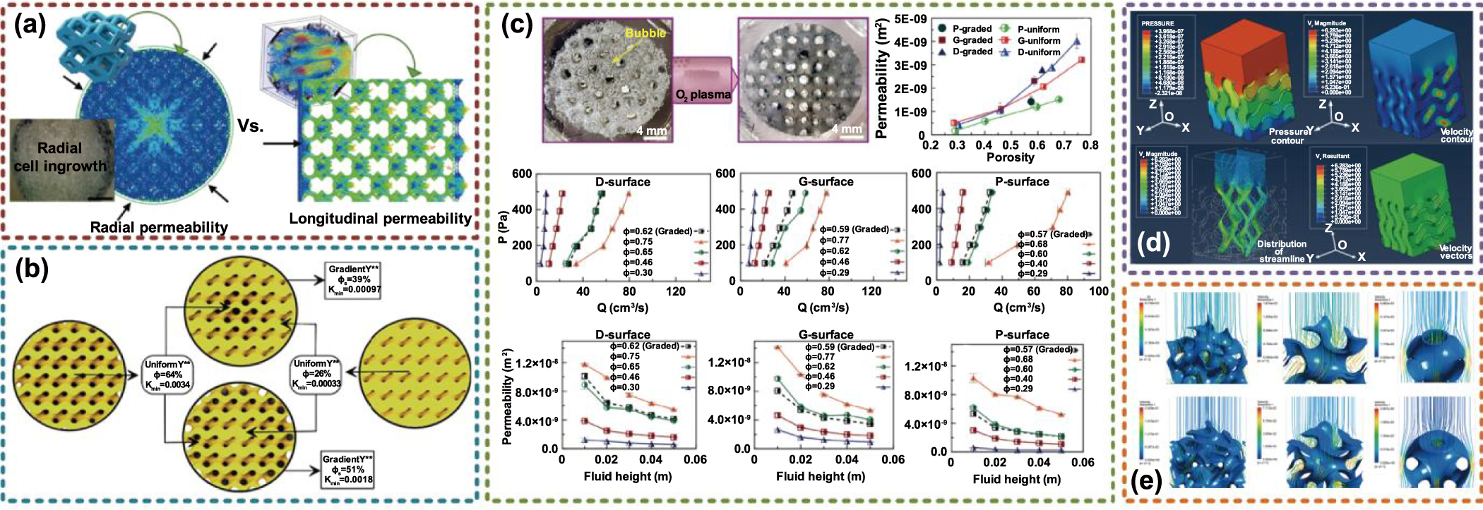
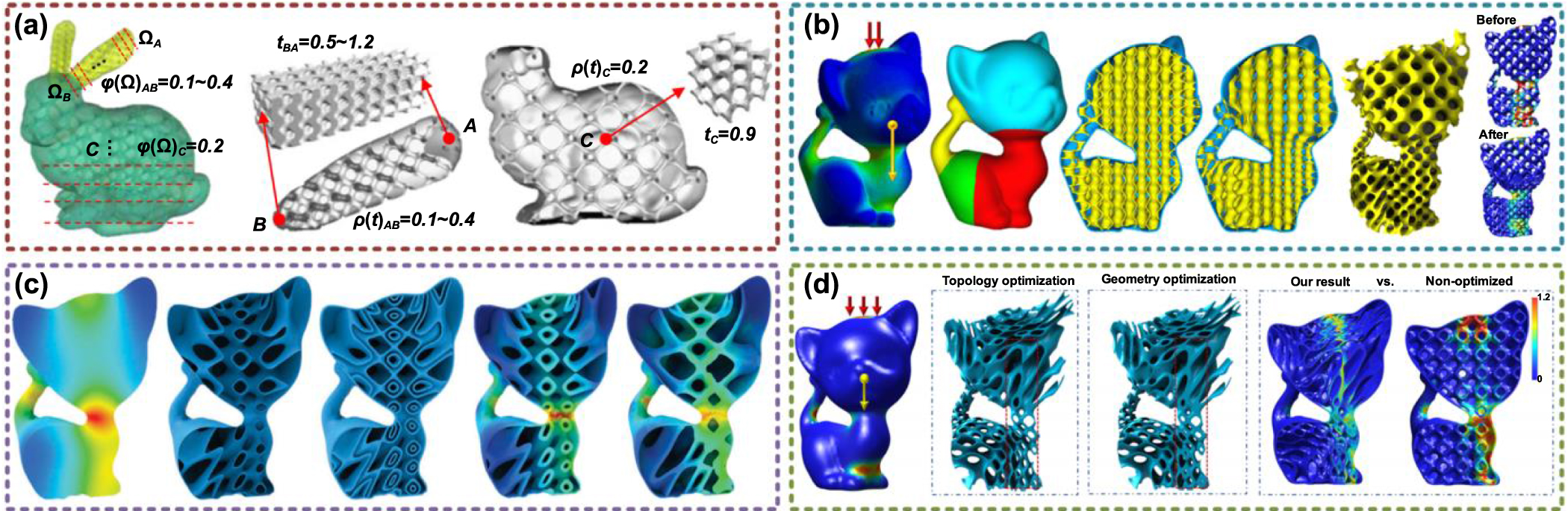
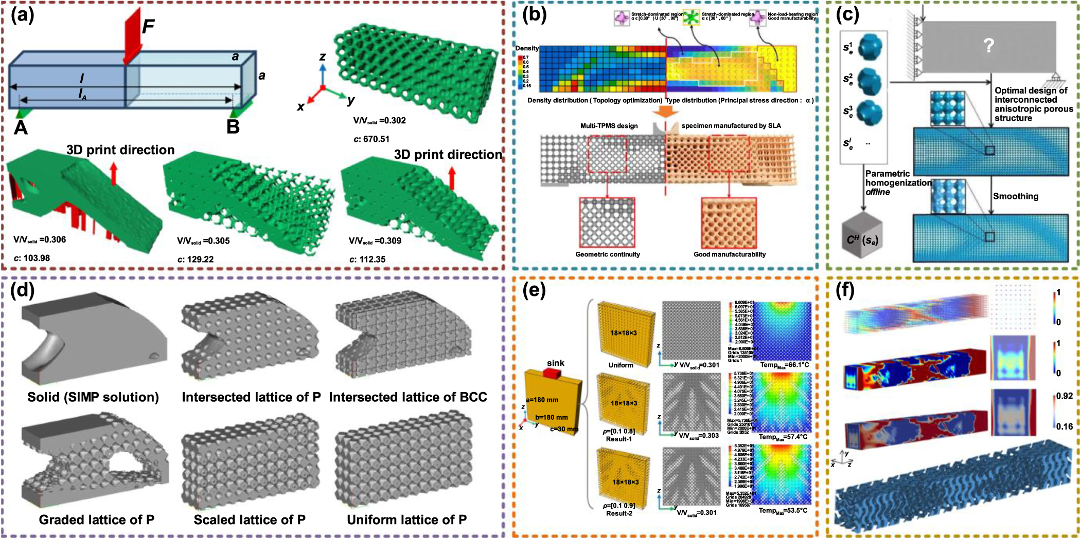
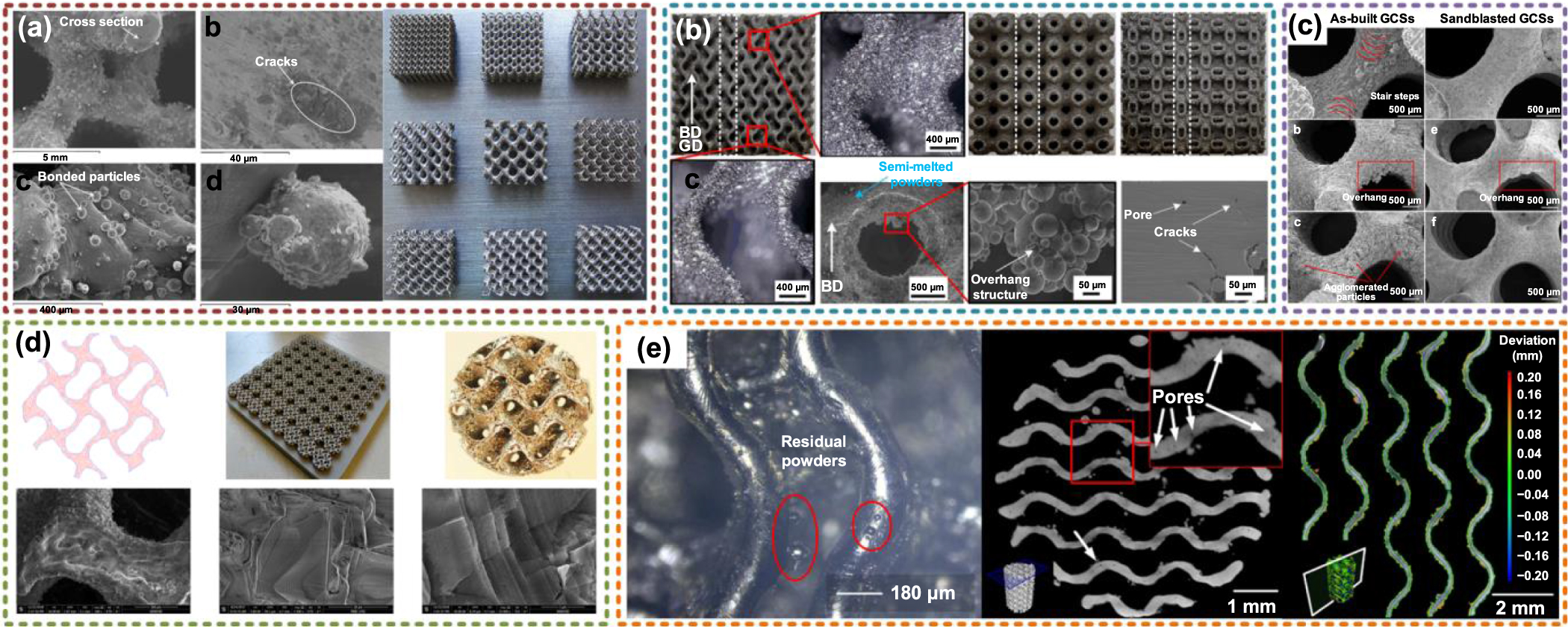
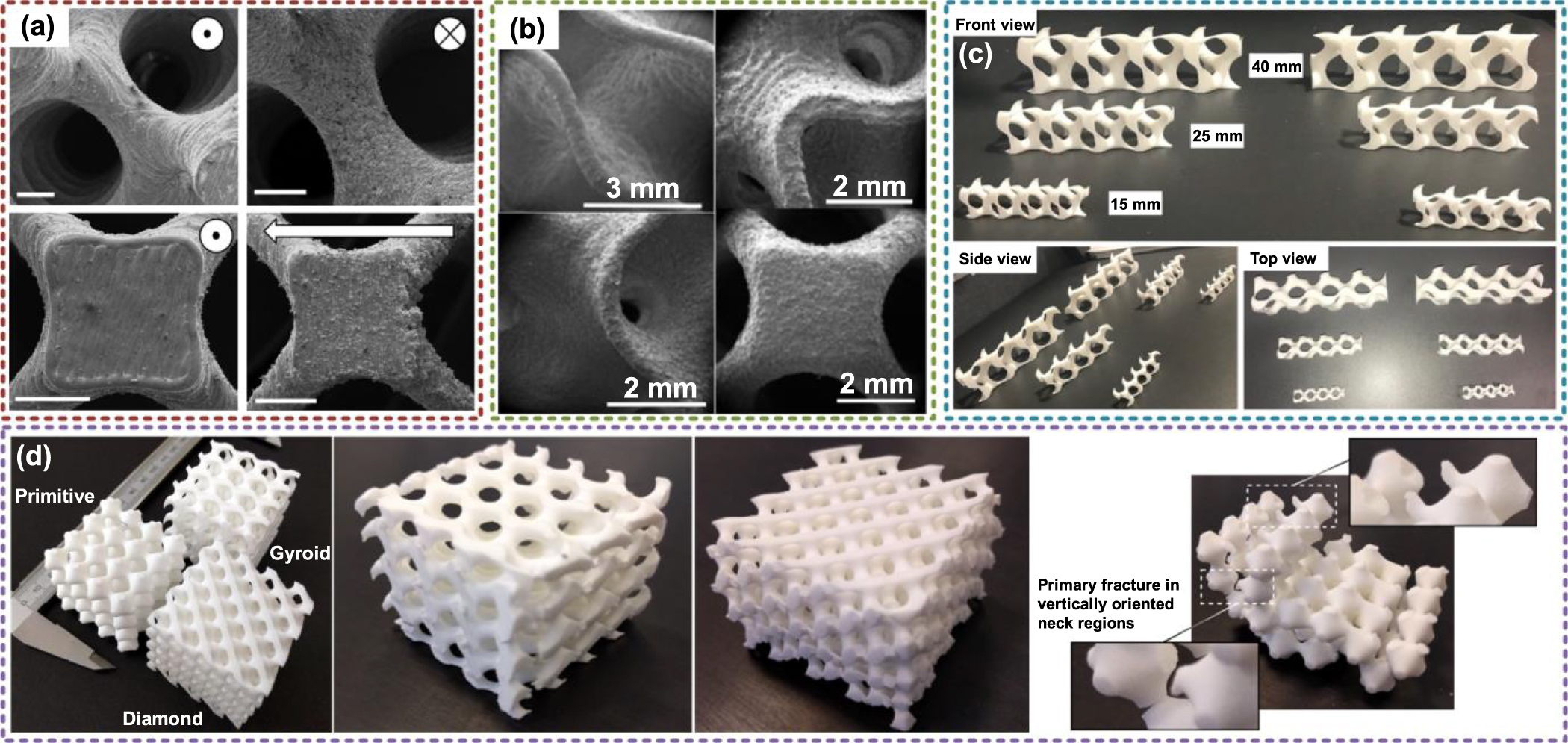
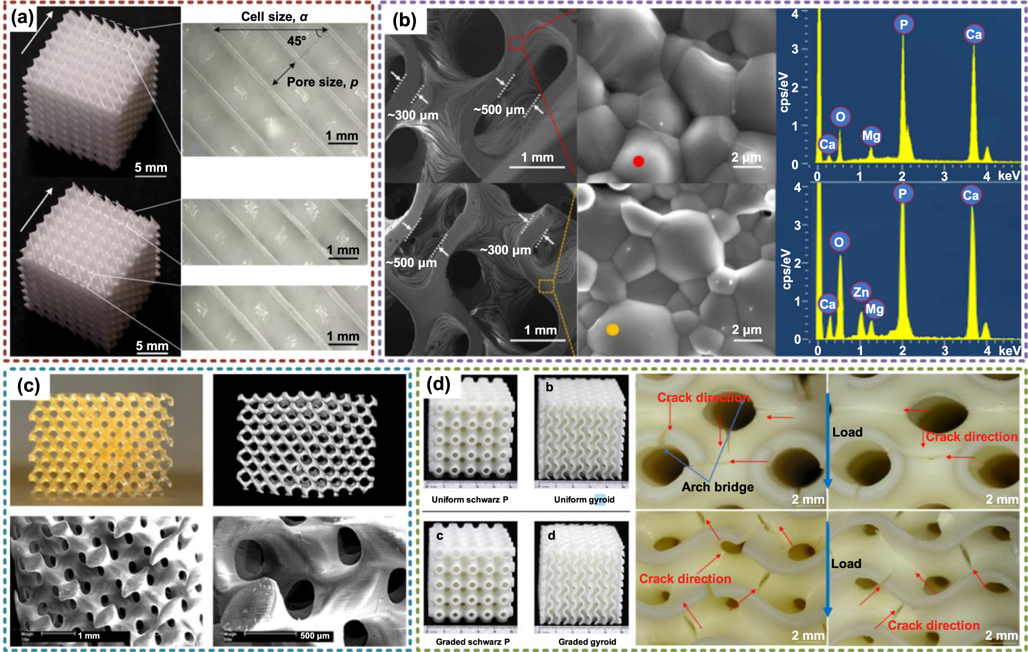
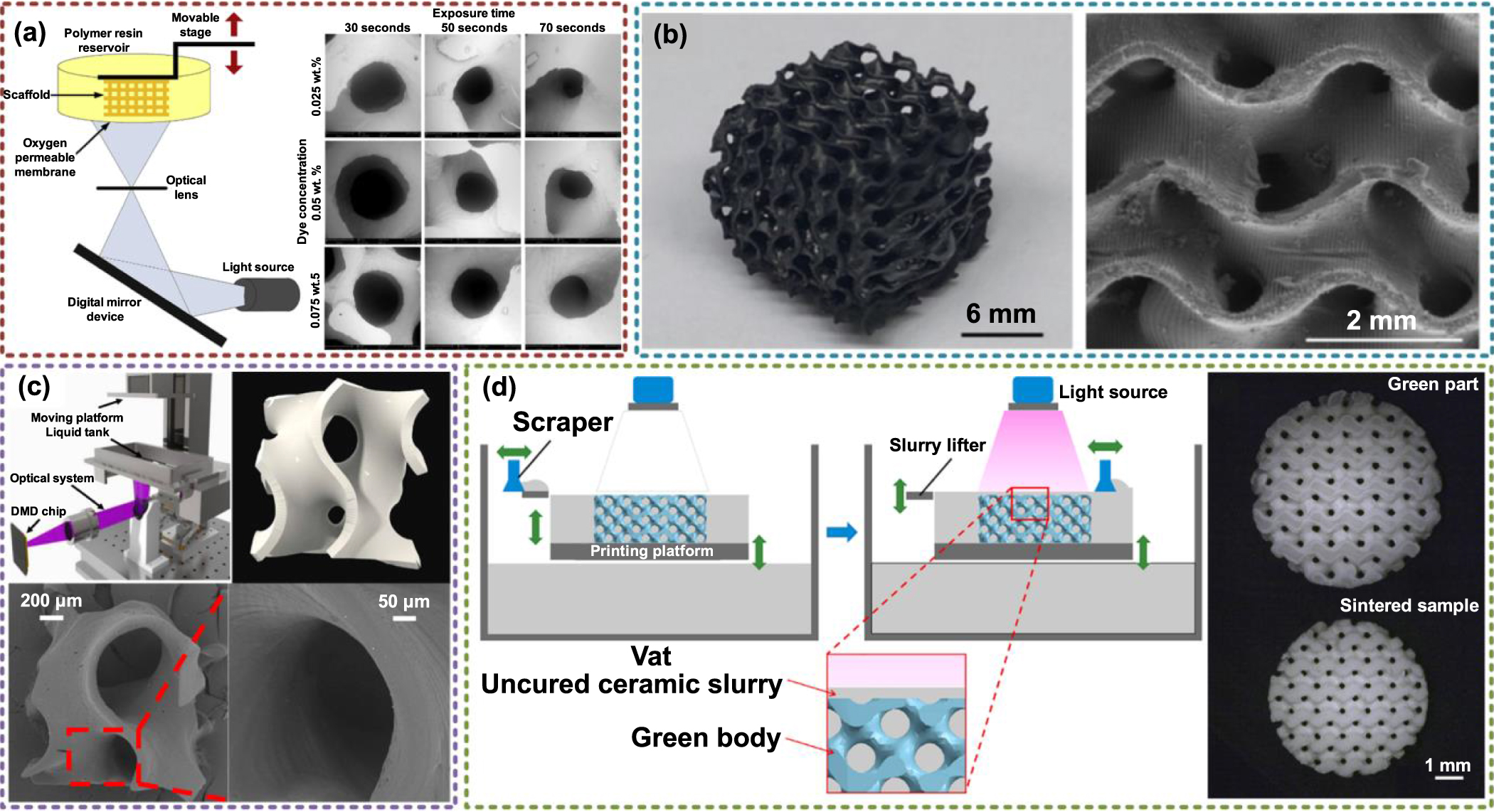
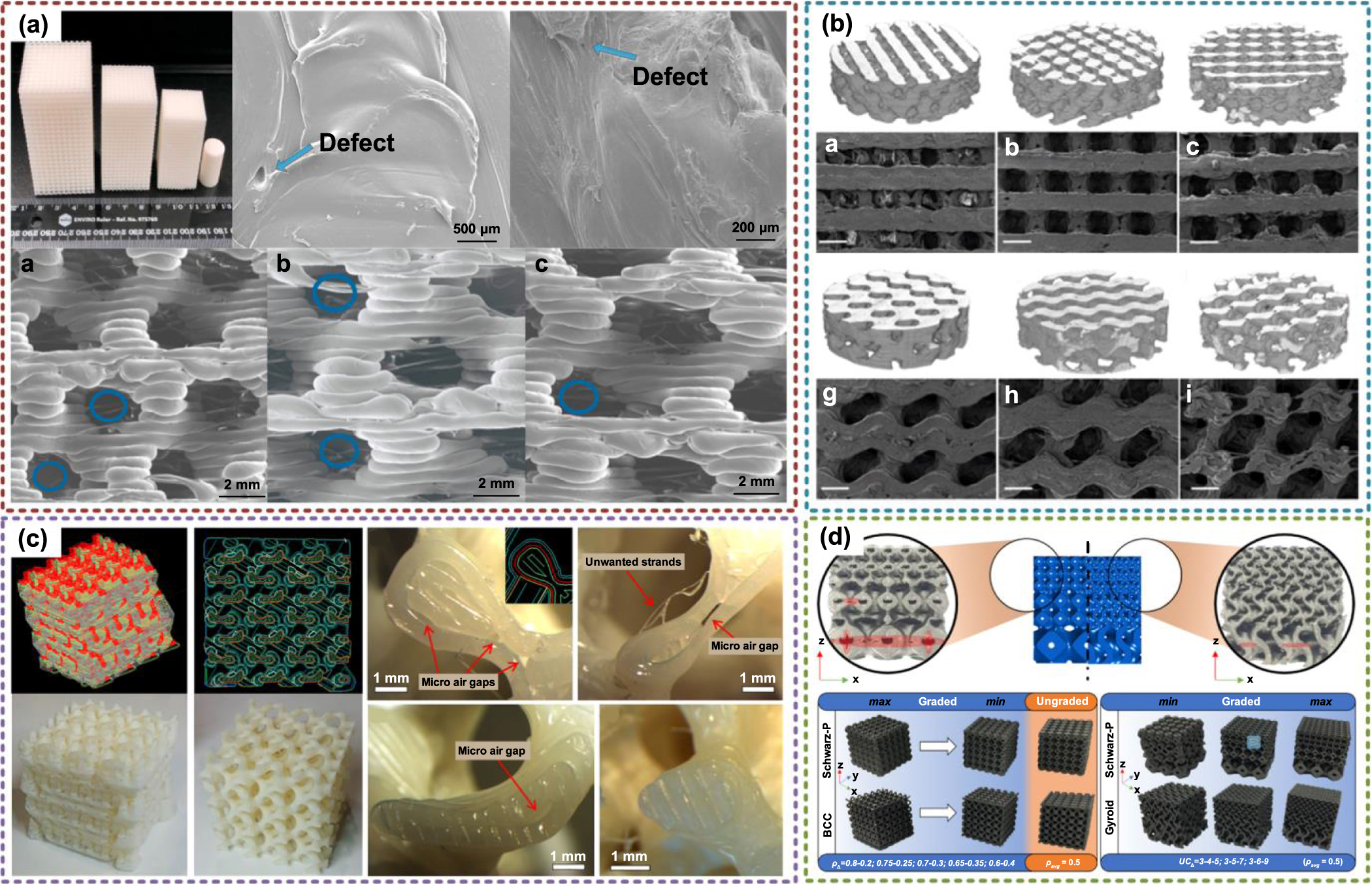
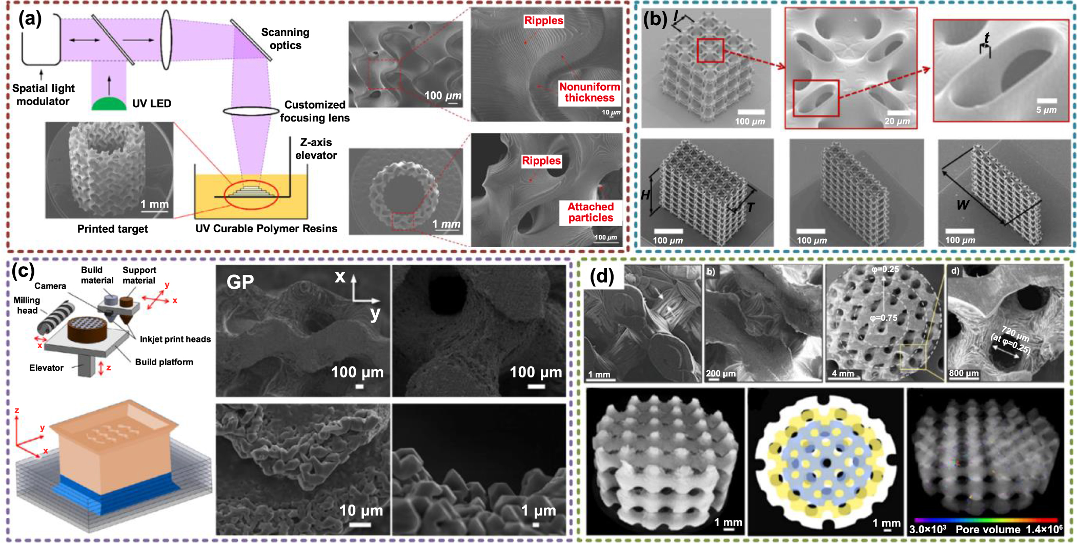
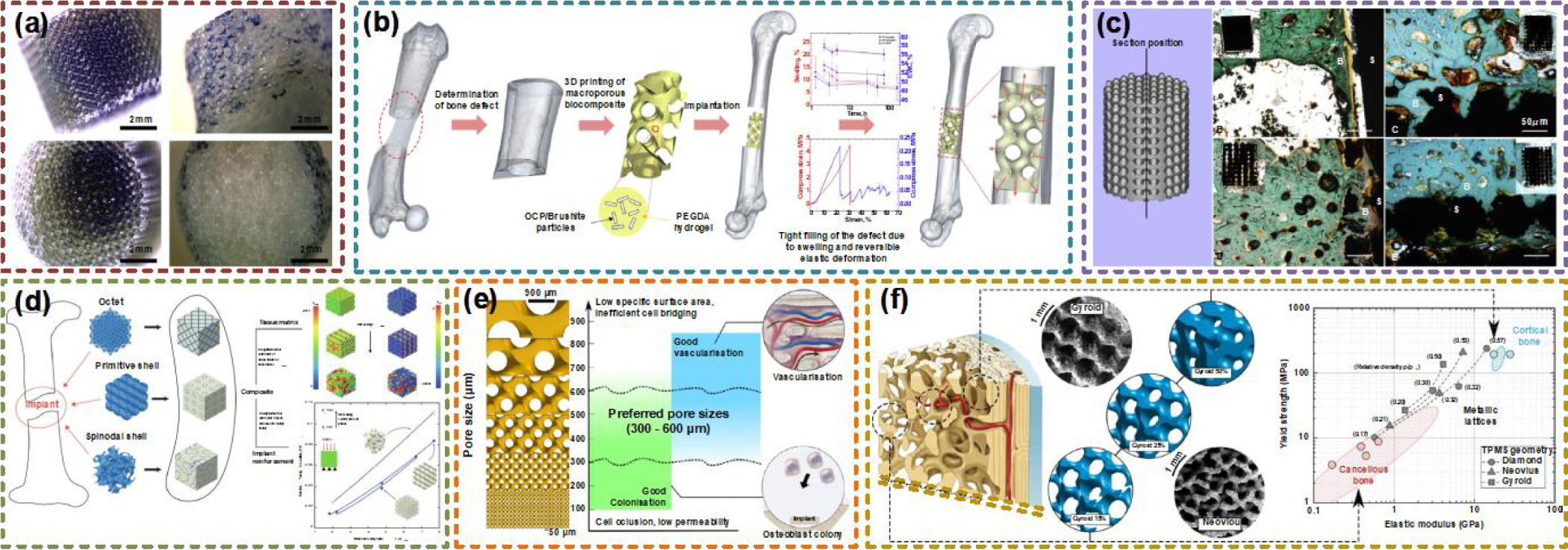
Figure 22. Acoustic and optical applications of TPMS structures. (a) TPMS electromagnetic microwave absorber. Reproduced with permission from [66]. Copyright 2021, Elsevier. (b) Acoustic band gaps of TPMS. Reproduced with permission from [188]. Copyright 2018, Elsevier Ltd. (c) TPMS with complete phononic bandgaps. Reproduced with permission from [64]. Copyright 2017, American Chemical Society. (d) TPMS photonic crystal. Reproduced with permission from [67]. Copyright 2015, John Wiley and Sons. (e) TPMS optical metamaterials. Reproduced with permission from [189]. Copyright 2018, the Authors.
Download figure:
Standard image High-resolution image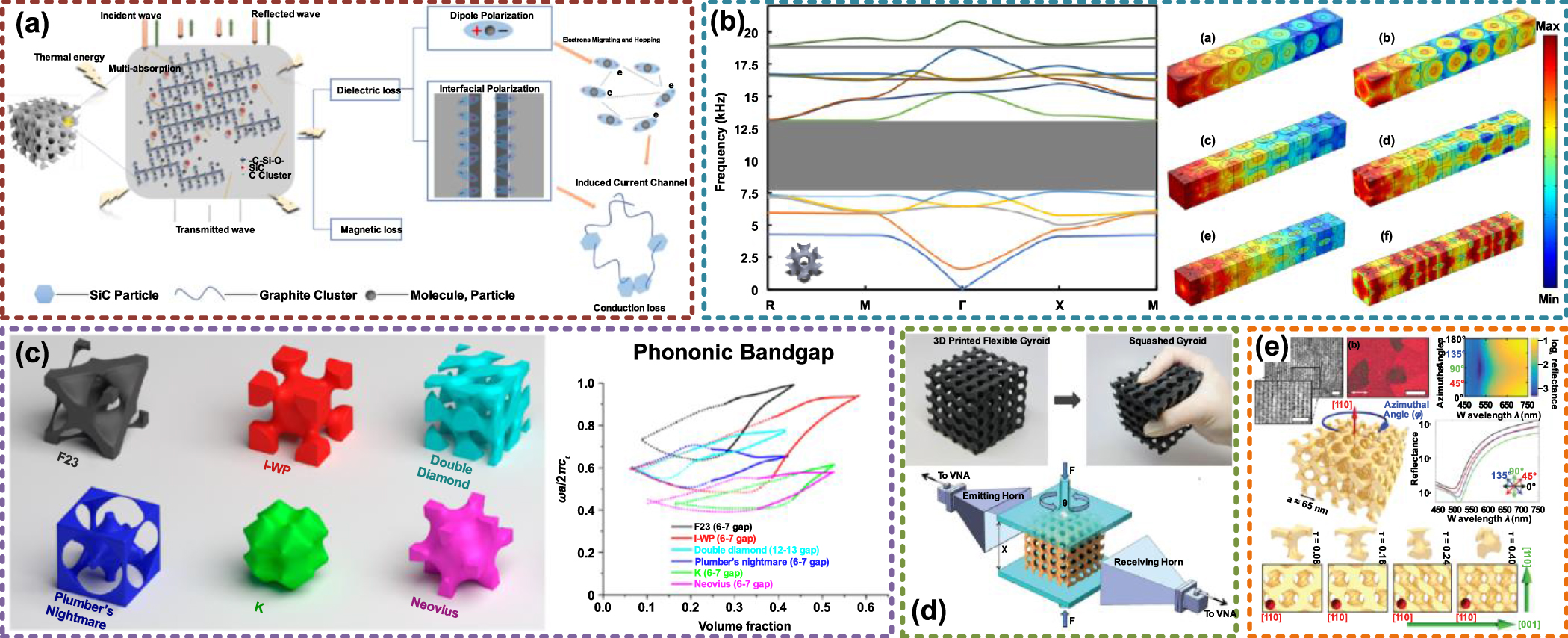
6. Conclusions and outlooks
In this review, the main design, manufacturing, and application research of TPMS structures in recent years were systematically summarized. More specifically, the design methods of TPMS were defined as the multiscale design strategies according to the actual complex requirements. According to the geometry demands, the TPMS porous structures need to be designed as similar to natural architecture as possible for inheriting functional outstanding merits, including graded porosity, heterogeneous features, multiscale pores, and complex freeform external shapes. With regard to the performances, the multifunctional performances of TPMS can be conveniently controlled by the design freedom supplied by the geometry design approaches. Hence, after geometry design and performance control, ideal geometric models of TPMS can be acquired. After that, precise manufacturing technologies are needed to make TPMS from CAD models to the physical objects which can be used. Actually, the basic mathematical expressions and geometries of TPMS were studied for a long time. However, due to the limits of conventional manufacturing methods, TPMS can hardly be fabricated by milling or turning. The rapid development of additive manufacturing promotes the prosperity of TPMS research and applications. The 3D porous features can be simplified as the accumulating results of 2D sliced layers. In virtue of different material and precision technologies, TPMS structures can be fabricated with ideal accuracy in different scales. Eventually, the resulting TPMS structures can be successfully applied in different domains. Due to the smooth surfaces and highly interconnected porous architectures, the actual application performances can even be superior to conventional solutions. Though promising, there are still many challenges and interesting problems which need more research attention.
At the geometric design stage, the design freedom of current methods is still not enough for complex applications. Numerous natural porous architectures cannot be accurately reconstructed. Most of the current CAD algorithms are based on Boolean operations. However, the calculation time and space consumption are much higher than normal solid structures. Some calculation processes of complex structures may be interrupted due to resource depletion. Moreover, the generation qualities of Boolean operations may be not acceptable. Especially for complex TPMS porous structures, numerous errors or cracks will appear after intersection operations. More efficient and adaptive design strategies are needed to construct ideal TPMS structures. Moreover, the design methods of current porous structures including TPMS, lattice, foam, and honeycomb are completely different. If a universal design framework can be developed in the future, the advantages of different topologies may be utilized together.
Although diverse geometric features can be generated by CAD algorithms, most of current performance control research is still based on uniform TPMS structures. Only a small amount of mechanical research is based on graded TPMS. Currently, too much research attention has been payed to the mechanical performances of TPMS. The compression performances have been discussed with different manufacturing materials. More studies of the heat and mass transfer performances of TPMS, especially heterogeneous TPMS and multiscale TPMS are needed. More importantly, multifunctional performances are urgently needed. How to make a trade-off among different requirements is a great challenge. Note that, there are many kinds of TPMS units that can be selected for generating porous structures. A smart system is needed to construct TPMS structures with suitable TPMS units and optimal porosity distributions according to the required multifunctional demands.
With regard to additive manufacturing technologies, diverse fabrication principle and materials can be chosen for different applications. However, the particularity and limitation of TPMS structures are not comprehensively considered in current research. Due to the sheet topology, there are many thin and isolated areas in the sliced layers of sheet TPMS structures. Although the paths of TPMS for additive manufacturing can be generated by the common methods, there is still great potential for improvement in efficiency and quality. Actually, necessary support structures are still needed for fabricating TPMS structures. Hence, some manufacturing requirements or limitations can be regarded as restrictions in optimization algorithms to obtain the optimal porosity for both manufacturing and applications.
Owing to these outstanding merits, TPMS structures have been successfully applied in different domains. Among these applications, TPMS tissue engineering scaffolds or implants are mostly discussed in recent research. All the mechanical, mass transfer, and cell growth performances and advantages can be verified by TPMS scaffolds. As discussed before, there is still great potential to apply TPMS in other multidisciplinary areas. With help of the ideal geometry shapes, reliable performances, and precise manufacturing quality, TPMS structures will play greater roles in future multidisciplinary applications.
Acknowledgments
This work was financially supported by National Key R & D Program of China (No. 2020YFC1107103), Key Research and Development Program of Zhejiang Province (No. 2021C01107), China Postdoctoral Science Foundation (No. 2020M681846), and Science Fund for Creative Research Groups of National Natural Science Foundation of China (No. 51821093).