

Abstract
Over the past few decades, a new branch of plasma research, nanomaterial (NM) synthesis through plasma–liquid interactions (PLIs), has been developing rapidly, mainly due to the various, recently developed plasma sources operating at low and atmospheric pressures. PLIs provide novel plasma–liquid interfaces where many physical and chemical processes take place. By exploiting these physical and chemical processes, various NMs ranging from noble metal nanoparticles to graphene nanosheets can easily be synthesized. The currently rapid development and increasingly wide utilization of the PLI method has naturally lead to an urgent need for the presentation of a general review. This paper reviews the current status of research on PLIs for NM synthesis. The focus is on a comprehensive understanding of the synthesis process and perceptive opinions on current issues and future challenges in this field.
Export citation and abstract BibTeX RIS
1. Introduction
Plasmas are one of the four fundamental states of matter in addition to solids, liquids and gases, and they are highly relevant to human life and modern industry. Plasmas resulting from the ionization of neutral gases generally contain an equal number of positive ions and negative electrons (negative ions in some cases), in addition to neutrals, metastables, excited atoms or molecules, reactive radicals, ultraviolet (UV) light and a strong electric field. Based on the flexible reactivity of the species in plasmas, gas-based reactive plasmas are widely used in manufacturing industries, such as the surface modification of materials and surface processes in integrated circuit processing [1].
Over the past few decades, a new branch of plasma research, nanomaterial (NM) synthesis through plasma–liquid interactions (PLIs), has been developing rapidly, mainly due to the various, recently developed plasma sources operating at low and atmospheric pressures. In PLIs, plasmas are over or inside liquids, providing plasma–liquid interfaces where many physical and chemical processes can take place, and these processes can be used to synthesize various NMs. In fact, the idea of forming materials from PLIs is not new, it appeared long before the term 'plasma' was used to describe a glowing discharge by Irving Langmuir in 1928 [2], and can be dated back to 1887 when Gubkin [3] used a discharge to reduce silver ions (Ag+) in an aqueous solution of AgNO3. After this inspiring work, only a few studies of material synthesis from PLIs followed, for example, iodine production from aqueous solution of potassium iodide [4], the formation of hydrogen peroxide from dilute sulfuric acid solutions [5, 6] and amino acid synthesis from elemental carbon related materials [7–10]. The reasons for this may have been a lack of interest on the part of researchers in forming materials and a lack of the requisite equipment to probe the materials formed (usually at a scale of nanometers) during that period. On the other hand, much interest was focused on electrolysis induced by PLIs, which was comprehensively explored by Hickling et al [6, 11–13] using the liquid as the cathode. The violation of Faraday's law regarding charge transfer in typical electrolysis was observed, i.e. the chemical effects produced by the PLI system are far larger than those predicted by Faraday's law [5, 14], which is explained by the fact that complicated chemical reactions, induced by liquid irradiation by energetic ions (in the plasma) at the plasma–liquid interface, are present in addition to charge transfer. A detailed review was presented recently to summarize the charge transfer processes at the plasma–liquid interface [15].
All these pioneering works demonstrate that a great number of physical and chemical processes involving the bulk plasma and the liquid, as well as the plasma–liquid interface, exist in plasma–liquid systems. Therefore, many applications can take advantage of the unique properties of PLIs, including drinking and waste water treatment [16–19], hydrogen peroxide production [11, 20], plasma medicine [21–24], liquid analysis [25–34], etc. It is well known that NMs are bridges between bulk materials and atomic or molecular structures, making them of great scientific interest. Differing from their bulk counterparts, the properties of nanoparticles (NPs) are, for example, usually size-dependent and when the particle's size approaches the nanoscale, the number ratio of surface to bulk atoms increases rapidly, which usually affects the quantum confinement in semiconductor particles [35], localized surface plasmon resonance (LSPR) in metal particles [36], superparamagnetism in magnetic materials [37] and the melting temperature [38] as well as the catalysis capability [39] of materials. A successful route for synthesizing NMs, solution-based synthesis, is based on the etching and/or reduction of metal ions in solutions [40, 41], which has proved a powerful tool for forming NMs of various sizes, shapes and compositions. Since the plasma can provide electrons and radicals, and the metal ions can dissolve in the liquid, the unique plasma–liquid system is strongly attractive for NM synthesis. The field of PLI-based NM synthesis [42–49] has grown significantly in recent decades due to the growing requirement for large-scale synthesis of NMs and the rapid development of various plasma sources.
Dendrites of several metals were obtained in a vacuum system in 1970 using a glow discharge electrolysis of molten metal salts [50]. C60 was formed by electric discharges in liquid toluene [51] in 1993. In 1998, Sano et al [52, 53] reported high-rate carbon 'onion' fabrication using graphite arc discharge in water. To our knowledge, the first synthesis of Ag fine particles was achieved by Kawamura et al [54] in 1998. They demonstrated the synthesis of microscale fine Ag particles by operating an atmospheric-pressure Ar direct-current (dc) plasma over a molten LiCI-KCI-AgCI eutectic, where the molten salt acted as the anode. The Ag+ in the molten salt was reduced to zero-valent Ag by reducing species in the plasma and then fine Ag particles were formed by the nucleation and growth of the zero-valent Ag in the molten salt. In principle, the electrons generated from the plasma cathode can reduce any metal ions in their molten form. This prototype, using the plasma as the cathode and the liquid as the anode, has been used in many subsequent instances of synthesizing NMs.
Reducing agents can be automatically produced during NM synthesis via PLIs, which is a key advantage in contrast to conventional, solution-based methods. The plasma includes not only free electrons and ions with certain energies depending on the discharge mode, but also radicals produced by PLIs and/or gas interactions. In addition to the free electrons, the ions and radicals can cause numerous physical and chemical reactions in the plasma–liquid interface and in the liquid. The NM formation can be attributed to the complicated physical and chemical processes in the PLIs, i.e. reduction, oxidation, sputtering, etc. The synthesis process can be controlled not only from the solution phase as in typical solution-based synthesis, but from the plasma phase, i.e. adjusting the reducing species yields by tuning the plasma parameters. Because the reducing species produced from the PLIs have different lifetimes and different reducing abilities [55], the process of NM synthesis can also be tuned by tailoring the relative yields of specific reducing species from the plasma phase. Although the diversity of reducing species in the PLIs increases the complexity of analyzing the synthesis mechanism, it also expands the routes available to tune the synthesis process. Moreover, the versatile radicals in the PLIs allow the possibility of controlling the shape and composition of NMs by adjusting the plasma parameters.
There are detailed reviews of the applications of PLIs [18–24] other than NM synthesis. Although a few review papers on NM synthesis using PLIs [56–61] can be found in the literature, they are either limited to the authors' own works or less comprehensive in terms of understanding and generality. We feel that, as we have passed the rudimentary period of NM synthesis using PLIs, there is an urgent need to present a general review including a comprehensive understanding of the synthesis process and perceptive opinions on the promising future of this method.
This review aims to present a comprehensive description of the physical and chemical processes that take place during NM synthesis using PLIs, and summarizes the recent improvements and progress in this field. This review is organizes as follows. After this general introduction, section 2 presents a brief introduction to the physical and chemical processes which occur in PLIs. Section 3 summarizes the achievements in NM synthesis from PLIs. Section 4 describes the current issues that need to be addressed in NM synthesis using PLIs and discusses the possible solutions. Finally, we summarize our main points and give an outlook for future work.
2. Physical and chemical processes in plasma–liquid interactions
The chemical reactions in NM synthesis from PLIs are in fact fairly simple. Most of the reactions are based on the reduction of metal or semiconductor ions by electrons provided by the plasma species, although in some cases the building blocks of the NMs originate from simple, direct physical processes such as the sputtering or evaporation of target materials without chemical processes. Coupling the complexity of both the plasma and the liquid, the plasma species that are able to provide reducing electrons are quite intricately dependent on the gas type, the type of power source, the discharge pressure, the liquid properties, the electrodes' configuration, etc.
The physical and chemical processes in a pure gas phase plasma have been studied intensively by many researchers and technicians in order to elaborately control these processes for numerous industrial applications. However, studies of the physical and chemical processes in PLIs have only attracted the attention of researchers in recent decades due to the beneficial applications in water treatment [16–19], plasma medicine [21–24], NM synthesis [42–49], surface engineering [62–65], etc.
Although there are various types of plasma–liquid systems, they can be simply classified as plasma over the liquid and plasma inside the liquid. In both classes, there is a plasma–liquid interface in addition to the liquid phase and the gas phase plasma. The plasma–liquid interface is an important zone for NM synthesis in which many physical and chemical reactions can be induced by PLIs. In this section, we will give a comprehensive analysis of the physical and chemical processes which appear in PLIs. The synthesis based on mainly physical processes is discussed after the synthesis based on mainly chemical processes. It is well known that the power sources used to drive a plasma come in many forms, including dc, pulse, microwave, radio frequency, etc, but here we focus our discussion on plasmas driven by a dc source. These conclusions can be partially extended to other sources. In the following section, we seek to give a clear description by illustrating the possible processes.
2.1. Chemical processes
2.1.1. Plasma over liquid.
In the plasma over liquid case, the analysis is carried out by forming a dc plasma with the liquid acting as the anode or cathode. The results can be generalized to many similar cases.
Kaneko et al [66, 67] investigated the plasma potential distributions for a dc plasma–liquid system at low pressure in an Ar atmosphere. High vapor pressure liquids, such as water or ethanol, are unstable at low pressures due to evaporation. Therefore, volatile liquids are not suitable for low-pressure plasma–liquid research. Due to the negligible vapor pressure of ionic liquids (ILs) [68], the authors used ILs in their experiments. The potentials in the plasma and the IL were measured using a Langmuir probe and an electrostatic probe, respectively. Figure 1 presents the plasma potential results for the IL as both the cathode and anode. Similarly to a traditional solid-electrode system, the authors found that there is a large cathode fall at the IL surface when the IL acts as the cathode, while there is no voltage fall at the IL surface when the IL is the anode. The results were confirmed by optical emission spectra detected from the plasma, implying an irradiation of energetic ions onto the IL surface in the liquid cathode case and a low energy electron shower onto the IL surface in the liquid anode case. These results are very important for understanding the processes in PLIs. Because many experiments on plasma–liquid systems use aqueous solutions, we present the detailed processes by exemplifying a plasma–aqueous solution system in the following.

Figure 1. Plasma potential distributions along the axis of the electrodes for liquid as (a) the cathode and (b) the anode. Reprinted with permission from [67], copyright 2009 John Wiley & Sons.
Download figure:
Standard image High-resolution imageThere are many partial interpretations [42, 44, 46, 48, 55, 57, 69–73] of NM synthesis from PLIs. Here we summarize these and try to provide a general mechanism. It is worth pointing out that the plasmas are operated from tenths of kPa to atmospheric pressure and they usually have a small size and low gas temperature due to the volatility of water. As shown in figure 2, Ar plasma is generated over an aqueous solution of a metal salt. An inert metal plate such as Pt is immersed in the solution to conduct the circuit. The physical and chemical processes are illustrated for plasma–liquid systems with the aqueous solution as the cathode (figure 2(a)) and the anode (figure 2(b)). There are dissolved metal ions (Mn+) in the solution, which are the precursors of the final metal NPs. The chemistry can be simply expressed as

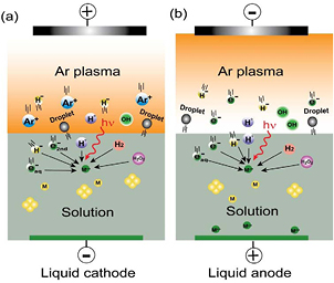
Figure 2. The physical and chemical processes in NM synthesis from PLIs. The liquid acts as (a) the cathode and (b) the anode. Modified with permission from [55], copyright 2012 The Japan Society of Applied Physics.
Download figure:
Standard image High-resolution imageHowever, the electrons provided by the plasma can arise in very different ways.
Figure 2(a) presents the processes for the liquid cathode case, as indicated in figure 1(a) there is a large cathode voltage fall at the liquid surface. The Ar ions in the bulk plasma will be driven by this voltage fall to move toward the liquid surface. When they reach the surface they will hold an energy in the order of tens to hundreds of eV, depending on the gas pressure and the discharge voltage. Then the energetic ions attack the liquid surface, creating some secondary effects, such as generating secondary electrons and decomposition of the constituents in the liquid. In addition to sustaining the bulk plasma, the secondary electrons can dissolve into the water to form hydrated electrons  which have a very strong reducing ability [74]. In the aqueous solution case, water molecules will be decomposed into atomic H and an OH radical, which has been confirmed by optical emission spectra detected near the liquid surface [55]. Atomic H can combine to form H2. In addition to direct combination of OH radicals,
  can be formed in PLIs by many different pathways [20]. Atomic H and H2 are able to reduce metal ions in the solution. In addition, depending on the pH values,
  presents different reducing abilities [75–77] for certain metal ions although it is usually a strong oxidizing species, for example, Au (III) reduction by

Dissociative electron attachment can lead to the formation of hydride (H−) [78] which is a very strong reducing species and can be dissolved into the liquid,

UV light is usually observed in plasma–liquid systems [79, 80]. Therefore, the high energy of UV photons can be transferred to water molecules, producing potential reducing/oxidizing species,

The solution components can be forced into the plasma–liquid interface and even into the bulk plasma by sputtering and/or evaporation [81–83], but this fact is usually ignored by researchers when considering metal ion reduction by PLIs. The solution components will take the form of a droplet in the plasma–liquid interface and/or in the bulk plasma due to the transport by sputtering and/or evaporation. The droplets have a large ratio of surface to volume and therefore they can meet many more electrons (including the bulk plasma electrons and electrons produced from the reactive radicals) compared to the liquid at the surface, leading to a more efficient reduction of the metal ions in the droplets.
For the liquid anode case, as indicated in figure 1(b), there is no voltage fall at the liquid surface. Electrons from the bulk plasma shower onto the liquid and the electrons can dissolve into the liquid to form  In addition, atomic H, H−, OH, H2 and
  can be produced in the bulk plasma by decomposing water vapor and cascade reactions, but the yields should be much smaller than those in the liquid cathode case. UV light can also function as the energy source for producing atomic H and OH. Due to the lack of strong irradiation by energetic ions on the liquid surface, fewer droplets can be formed in the plasma–liquid interface and the bulk plasma, and the metal ions in the droplets can be reduced by the electron providers around them.
As discussed above, the yield of reducing species generated by the liquid cathode is much larger than that by the liquid anode, although they can generate the same reducing species. Thus, the reducing efficiency of the liquid cathode is higher than that of the liquid anode. This phenomenon can somehow influence the size and structure of the final products [40, 84, 85]. In addition to the reducing species, the oxidizing species, atomic O [86], O3 [87], OH radicals, etc, can also be generated in PLIs. All species can diffuse into the liquid. OH radicals are easily combined into  they then pass through the liquid surface and drift in the solution.
  as well as dissolved O2 can act as oxidizing species. As a result, reactive metals such as iron, cobalt, etc, might be oxidized after the formation of metal NPs by reduction of metal ions. In order to provide a clear description, we summarize the standard reduction potential (E°) versus standard hydrogen electrode (SHE) values of partial reactive species in PLIs in table 1, in which some species not mentioned in the above analysis are also included.
Table 1. Standard reduction potentials (E°) versus SHE for partially PLI-induced reactive species and some metal ions.
| Reactive species | Reaction | Eo (V) | Reference |
|---|---|---|---|
| Free electron | N/A | ||
| Secondary electron | N/A | ||
| Hydrated electron |  + e− → + e− →  |
–2.87 | [88] |
| H | H+ + e− → H | –2.30 | [88] |
| H− | H2 + 2e– → 2 H– | –2.40 | [334] |
| Hydrazine | N2 + 4H+ + 4e− →  |
–1.21 | [335] |
| H2 | 2H+ + 2e− → H2 | 0.00 | [90] |
 |
O2 + 2H+ + 2e− →  |
+0.70 | [334] |
 + H+ + e− → OH + + H+ + e− → OH +  |
+0.96 | [334] | |
 + 2H+ + 2e− → + 2H+ + 2e− →  |
+1.76 | [90] | |
 + 2OH– → O2 + + 2OH– → O2 + + 2e− + 2e− |
+0.15 | [77] | |
| O2 | O2 + 4H+ + 4e− →  |
+1.23 | [77] |
| O3 | O3 + 2H+ + 2e− → O2 +  |
+2.08 | [336] |
| O | O + 2 H+ + 2e− →  |
+2.43 | [337] |
| OH | OH + H+ + e− →  |
+2.85 | [338] |
| Au3+ | Au3+ + 3e− → Au | +1.50 | [334] |
 |
 + 3e− → Au + 4 Cl− + 3e− → Au + 4 Cl− |
+1.00 | [339] |
| Ag+ | Ag+ + e− → Ag | +0.80 | [77] |
| Ag2+ | Ag2+ + e− → Ag+ | +2.00 | [340] |
| AgCl | AgCl + e− → Ag + Cl– | +0.22 | [77] |
| AgO | 2AgO + H2O + 2 e− → Ag2O + 2OH– | +0.60 | [340] |
| Cu2+ | Cu2+ + 2e− → Cu | +0.40 | [90] |
| Fe2+ | Fe2+ + 2e− → Fe | –0.44 | [90] |
| Mg2+ | Mg2+ + 2e− → Mg | –2.36 | [90] |
| Cs+ | Cs+ + e− → Cs | –3.03 | [90] |
Free electrons from the bulk plasma and secondary electrons from ion irradiation on the liquid surface have much strong reducing abilities due to the their high energies; they can reduce almost any metal ion in its molten form or most metal ions in an aqueous solution. For other reducing species, we can estimate their reducing ability by their E°. The  from the solvation of electrons have a very strong reducing ability (E° = −2.87 V versus SHE [88]) although they have a short lifetime (approximately nanoseconds to microseconds depending on the medium [89]). Based on the E° data in [90], we can roughly estimate that
  can spontaneously reduce most metal ions, even the much weaker oxidants of Fe2+ and Mg2+, in an aqueous solution, while the spontaneous reduction of Cs+ (E° = −3.03 V) by
  is not feasible. If the solution interacting with the plasma is composed of chloroauric acid (HAuCl4), then the metal ions will take the form
 ![${{\left[\text{AuC}{{\text{l}}_{x}}{{\left(\text{OH}\right)}_{4-x}}\right]}^{-}}$](https://content.cld.iop.org/journals/0022-3727/48/42/424005/revision1/d510380ieqn029.gif) (x ≥ 2 at low pH values, x < 2 at high pH values) [91, 92]. Considering table 1 and taking
(x ≥ 2 at low pH values, x < 2 at high pH values) [91, 92]. Considering table 1 and taking  as an example, the species generated in PLIs, such as OH,
  and
and  can have the following possible reactions with
  in acidic (equations (5.1)–(5.3)) and basic (equation (5.4)) media,


The standard Gibbs free energy (ΔG°) [90] of a chemical reaction can be expressed as ΔG° = −nFE°, where n is the electron number involved in the chemical reaction and F is the Faraday constant  A chemical reaction is favored if ΔG° is negative and it is not favored when ΔG° is positive. Based on E° in table 1, ΔG° can be estimated to be −0.3 × 3 F, −0.04 × 3 F, +0.76 × 3 F and −1.15 × 3 F for equations(5.1)–(5.4), respectively. Therefore, equations (5.1), (5.2) and (5.4) can proceed spontaneously because of the negative ΔG°, while equation (5.3) cannot due to its positive value of ΔG°. From the ΔG° values, we can also see that it is much easier for equation (5.4) to proceed than equations (5.1) and (5.2), which means that
  is a stronger reducer for
  in a basic than in an acidic medium.
The behaviors of other metal ions and reducing species can also be analyzed in the same way. Because the reducing species in plasma over liquid can only penetrate a certain depth of the bulk liquid due to their limited energy and lifetime, the chemical reactions take place mainly at the plasma–liquid interface and at a limited depth under the liquid surface. We know that metal ions can be driven to move by an electric field applied in the liquid, for example, Ag+ and  will move toward the liquid surface and bottom, respectively, in the liquid anode case, which will influence the reaction rates and final products. Thus, according to the movement of metal ions by the applied electric field and the reducing abilities of existing species, the selection of suitable forms of metal ions is important for NM synthesis in a plasma over liquid system.
It is worth pointing out that the reducing species can be classified as two types in terms of their lifetimes: short-lived and long-lived species [55]. The short-lived reducing species include free electrons,  secondary electrons, atomic H, H− and UV light which disappear or quickly decay after the plasma irradiation is stopped. The long-lived reducing species consist of H2 and
  which can stay in the liquid for a long time, they can even be detected several months after the plasma irradiation. These two types of reducing species can be used to control the nucleation and growth processes of the synthesized NMs. The pH value of the solution can be also tuned to control the reaction processes in the solution since the reducing properties of
  for numerous compounds are stronger in basic media than in acidic ones [75–77]. In section 4.1, we will return to this subject for a detailed discussion.
In addition, as PLIs are usually operated in ambient air, N2 and O2 invariably enter the reaction zone, resulting in solution acidification through various cascade reactions of plasma-induced nitrogen species in the solution [93], such as the dissolution of nitrogen related species  [79, 94, 95]. H+ can also be created from water ionization by electron collision. Thereby, the liquid chemistry, such as the pH value, will be changed by the plasma irradiation, which can influence the rate and probability of chemical reactions in the liquid. We must pay attention to this if we want to elaborately control the synthesis. Interestingly, hydrazine
  has been observed after an exposure of N2 and CO2 [96] or Ar/ammonia [97] plasma on water, and PdNPs [98] and CuNPs [99] have been obtained from reductions of
 ![${{\text{K}}_{2}}\left[\text{PdC}{{\text{l}}_{4}}\right]$](https://content.cld.iop.org/journals/0022-3727/48/42/424005/revision1/d510380ieqn043.gif) or CuCl2 by hydrazine. Consequently, the reducing species in PLIs operated in air might include hydrazine since both N2 and CO2 are components of air. But we should point out that one must be very careful if one wants to use hydrazine (hydrate) and hydrogen peroxide as reducing agents, since the mixture of hydrazine (hydrate) and hydrogen peroxide is liable to be explosive.
or CuCl2 by hydrazine. Consequently, the reducing species in PLIs operated in air might include hydrazine since both N2 and CO2 are components of air. But we should point out that one must be very careful if one wants to use hydrazine (hydrate) and hydrogen peroxide as reducing agents, since the mixture of hydrazine (hydrate) and hydrogen peroxide is liable to be explosive.
Anodic dissolution has been used for electrochemical synthesis of PdNPs [100], AgNPs [101] and gold nanorods [102]. Anodic dissolution can also take place in PLIs since the plasma–liquid system is actually a modified electrochemical cell [15, 103]. Only a few studies have considered the effect of anodic dissolution in NP synthesis from PLIs [46, 69]. We should point out that anodic dissolution should not be omitted in controlling NM synthesis. If the material of the immersed plate electrode is the same as the dissolved metal ions  anodic dissolution can take place at the electrode, liberating
  into the solution, which will increase the concentration of
  The precursor concentration can strongly affect the size [84, 85] and structure [40] of the final products, and therefore this anodic dissolution can add uncertainty to the control of the final products. Also, anodic dissolution will add impurities to the final products if the material of the immersed electrode is different from the dissolved metal ions. In order to control the synthesis process, we must eliminate or minimize anodic dissolution, which can be realized by carefully selecting the solution composition, metal type, ambient gas and discharge type [104].
2.1.2. Plasma in liquid.
Differing from plasma over liquid, most plasmas in liquid are operated in liquid bubbles or small vapor channels. Figure 3 shows two types of plasmas: plasma in a bubble and streamer plasma in a small vapor channel. The discharge process of plasma in bubbles is similar to that of a glow discharge plasma in a gas phase and plasma over liquid since the bubbles consist of water vapor created by joule heating and electrolysis of water. The bubble plasma usually propagates along the plasma–liquid surface or across the bubble without contacting the liquid surface depending on the dielectric constants of the bubble gas and liquid [105, 106]. The streamer plasma in water is generated by a decrease of the liquid density around the electrode by electric field enhancement [107] under a high overvoltage, or direct electron collision induced liquid water ionization under an ultrahigh local electric field [108–111]. The streamer plasma takes on the form of multi-branched channels as shown in figure 3(c) and propagates in these small channels with very high speeds.
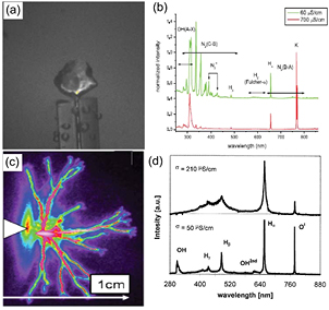
Figure 3. Photographs and optical emission spectra for plasma in a water bubble, (a) and (b), and for a streamer plasma in water, (c) and (d). (a) and (b) reprinted with permission from [112], (c) and (d) from [341] and [342], respectively, copyright 2009 [112], 2011 [341] and 1999 [342] IOP Publishing.
Download figure:
Standard image High-resolution imageAlthough the discharge processes are different for plasma in a vapor bubble and a streamer in a small vapor channel, they show similar reactive species in the bulk plasmas as presented in figures 3(b) and (d). The dominant species originate from the decomposition of water by plasma, atomic O, atomic H, OH radicals and sometimes also nitrogen related species due to residual dissolution of N2 in the studied liquid, although in most cases, nitrogen related species are neglectable.
As presented in figure 4(a), plasma in a vapor bubble will generate similar species to a plasma over liquid (except the species derived from the discharge gas, for example, N-containing species provided by discharges in air). Under some conditions, plasma localizes around the anode [112] or the cathode [113] bubble which is similar to the liquid cathode or anode case, and therefore it can be analyzed in the same manner as in the plasma over liquid case. However, the reactive species generated in the bubble can diffuse across the plasma–liquid interface and will enter the liquid when the bubble is broken [114], which frequently happens during operation and, as a result, the reducing efficiency should be relatively higher compared to the plasma over liquid.
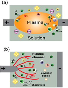
Figure 4. The physical and chemical processes in NM synthesis from (a) plasma in a bubble and (b) a streamer plasma in liquid.
Download figure:
Standard image High-resolution imageThe streamer plasmas in small channels, as described in figure 4(b), can produce shock waves and cavitation bubbles [115] in addition to the same reactive species as produced by plasma in a bubble. Shock waves can transfer energy to the liquid and produce cavitation bubbles in the liquid. Theses cavitation bubbles can experience a broken process and generate secondary small plasmas [116], which will enhance the yield of reducing species in the liquid.
Because both electrodes are immersed in the liquid, the final products might be contaminated by the electrodes' material. Therefore, the electrode materials and solution constituents must be carefully selected in order to decrease potential impurities as much as possible.
In addition to the aforementioned reduction of metal ions, the solvent decomposition is also used for NM synthesis from PLIs. Since plasma can generate rich reactive species, NMs might be formed by decomposing the solvents, such as carbon sphere formation from ethanol [117] and benzene [118] decompositions, and silicon nanocrystal surface engineering [65, 119] by functional groups produced from ethanol decomposition.
It is worth noting that in both plasma over and inside liquids, reactions in nonequilibrium can take place through thermal or electron impact activation.
2.2. Physical processes
The above discussion mainly concentrates on the chemical processes used to synthesize NMs from PLIs, but there are some cases where the physical processes are dominant. Two physical processes frequently used for NM synthesis in plasma–liquid systems are presented in the following sections.
2.2.1. Sputtering [120, 121].
As a representative example, figure 5 illustrates AuAgNP synthesis by sputtering in a plasma–IL system. An AuAg foil target is placed over the IL and a negative high voltage is applied to the target to generate an Ar plasma between the IL and AuAg target. As shown in figure 1(b), a high cathode voltage fall will be formed on the target after plasma generation. This cathode voltage fall will cause target sputtering by energetic ions (Ar+). Similar to traditional sputtering deposition, the sputtered target atoms will move toward the IL surface. Theses atoms will experience nucleation and growth to NPs on the liquid surface and inside the liquid due to the flexibility of the liquid, rather than forming a film on a solid substrate as in traditional sputtering deposition. The final AuAg composition and size can be controlled by the target composition and plasma parameters. The selection of an IL is based on its low vapor pressure which facilitates highly efficient sputtering and minimizes contamination in a low-pressure plasma.
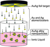
Figure 5. AuAgNP formation by sputtering AuAg in a plasma–IL system. Reprinted with permissions from [121], copyright 2008 RSC Publishing.
Download figure:
Standard image High-resolution image2.2.2. Evaporation [122, 123].
In addition to the sputtering process, evaporation of metal electrodes is also used in the synthesis of NMs, as shown in figure 6. In this case, a thin metal wire is partly immersed in an electrolyte solution as the cathode, while another inert metal, such as a Pt mesh, also immersed in the solution is used as the anode. When a gradually increasing voltage is applied to the cathode, joule heating generates water vapor which can cover the immersed part of the thin wire. A short-lived cathode spot can be ignited at the thin wire as voltage increases to the breakdown voltage of the water vapor. As a result, cathode spots exist on the thin wire surface. The localized temperature at the cathode spots is very high (several thousands to tens of thousands of °C) which can result in the fast evaporation of the cathode material, leaving craters on the cathode surface. This has been confirmed by checking the morphology of the thin wire surface after plasma operation [124, 125]. Consequently, the evaporated cathode materials will move to the liquid surface and they will be cooled down during their movement and finally quenched in the liquid, leading to the final formation of NPs. The quality and size of the NPs depend on the applied voltage as well as the electrolyte type and concentration.

Figure 6. Metal NP formation by evaporation of the electrode material. (a) Photographs of plasma evolution in an electrolyte solution under a certain voltage and (b) the mechanism of evaporation for the metal electrode. Modified with permission from [123], copyright 2007 American Institute of Physics.
Download figure:
Standard image High-resolution image3. Nanomaterials synthesized by plasma–liquid interactions
With reference to table 1 and [77], we find that the maximum E° of the reducing species produced by PLIs are larger than those of most metals and semiconductors in the periodic table, thus, in principle, NMs of most metals and semiconductors can be synthesized from PLIs. Thanks to the efforts of many research groups, the production a great number of different NMs has been achieved in the last two decades. We review these recent developments and progress in the following sections in terms of type of material. Each type of material is related to different configurations of plasma–liquid systems.
3.1. Noble metals
Au, Ag, Pt and Pd are usually categorized as noble metals and, except for Ag, they are resistant to corrosion and oxidation in moist environments. They have been used as jewelry and currency since ancient times. When their size approaches less than 100 nm, they display exotic optical, electronic, etc, properties, allowing numerous fundamental studies and engineering applications. AuNPs and AgNPs have extraordinary optical properties, such as the well-known LSPR which is a charge oscillation of the collective electrons at the NP's surface excited by light. LSPR can be tailored by particle size, composition and shape, giving AuNPs and AgNPs a great number of potential applications, such as surface-enhanced Raman scattering [126], nanomedicine [127] and biological sensing [39]. Although Au is chemically stable, AuNPs were found to have a fascinating catalytic ability for many oxidation reactions [128, 129] when the AuNPs are supported by  or TiO2, and this catalytic ability is closely correlated with the size of the AuNPs. PtNPs and PdNPs also possess unique catalytic abilities for CO oxidation [130, 131], hydrogenation [132, 133], etc. The NPs of these noble metals will play pivotal roles in the development of new technologies. Therefore, the synthesis of these noble metal NPs with a low cost, high quality and large scale yield is necessary for scientific research and practical applications. The PLI method provides a simple route to realize these aims.
In fact, these noble metals are dominant in metal NMs synthesis using PLIs because of their strong resistance to corrosion and oxidation, and their higher electrochemical series (i.e. the ions of noble metals capture electrons more easily). Some representative examples are presented in the following.
The synthesis of Ag nanowires was reported in 1999 from an arc discharge generated over an aqueous solution of NaNO3 with two silver filament electrodes, one over and the other immersed in the solution [134]. In 2005, Koo et al [42] fabricated PtNPs without any additional capping agent (a material covering the surface of the NPs to avoid aggregation) by exposing an atmospheric-pressure alternating-current (ac) H2/He plasma on an aqueous solution of  (figure 7(a)). The transmission electron microscopy (TEM) image in figure 7(b) indicates that the average size of PtNPs is about 2 nm and they demonstrate a nanocrystalline nature. The authors also found that the average size of PtNPs increased from 2 to 5 nm when the solution temperature changed from 10 to 40 °C. In that paper, the authors concluded that
  was reduced by atomic H with the assistance of H+, produced from the H2/He plasma. This is, in part, correct, however, the
  should be reduced not only by atomic H, but also by the other reducing species mentioned in section 2.1.1.
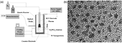
Figure 7. (a) The experimental set-up for the plasma–liquid synthesis of PtNPs and (b) a representative TEM image of the synthesized PtNPs. Modified with permission from [42], copyright 2005 The Royal Society of Chemistry.
Download figure:
Standard image High-resolution imageAfter the work of Koo et al [42], the noble metals of AuNPs [43, 46, 67, 71, 73, 135–142], AgNPs [46, 69, 143–147], PtNPs [67] and PdNPs [148–153] were intensively explored using plasma over liquid configurations.
Sankaran's group [46, 69] obtained AuNPs and AgNPs from a dc microplasma–liquid system with an H-shapes glass cell by reducing metal ions either originating from the solution or from anodic dissolution of Au (Ag) foil. Fructose was present in the solution to prevent agglomeration and precipitation of the particles. They found that the NPs were only formed near the plasma cathode as shown in figure 8(a) in the anodic dissolution. They attributed the NP formation to the plasma-provided-electron reduction of Au or Ag ions either from anodic dissolution or the pristine metal salt solutions. Recently, a similar experiment was performed by replacing the immersed metal anode with a plasma [154–156]. As shown in figure 8(b), AgNPs were only formed near the plasma cathode part from the AgNO3 solution, while there were no observable AgNPs in the plasma anode case, although the plasma anode can provide reducing species as described above. The reduced Ag might be oxidized to  or AgO since the plasma also generates oxidizing species. In addition to reaction
  reactions
 (E° = +0.60) might also occur in the solutions due to the negative sign of Gibbs free energy. It is interesting to note that AuNPs can be formed near both the plasma anode and cathode when using an aqueous solution of HAuCl4 in the same experiment (figure 8(c)). The AuNPs are concentrated near the plasma anode while the AuNPs near the plasma cathode display a slight concentration gradient. Thus a question arises: how do we understand the differences between the formation processes of AgNPs and AuNPs under similar plasma conditions? We suggest that the nature of the metal ion in the solution might give some insight into this question. Ag ions in the solution take the form of Ag+, while Au ions mainly take the form of
 ![${{\left[\text{AuC}{{\text{l}}_{x}}{{\left(\text{OH}\right)}_{4-x}}\right]}^{-}}$](https://content.cld.iop.org/journals/0022-3727/48/42/424005/revision1/d510380ieqn054.gif) (x ≥ 2 at low pH values, x < 2 at high pH values) [91, 92]. Therefore, they will move in the solution in different directions under the same applied electric field. Consequently, AuNPs and AgNPs are formed near the plasma anode and plasma cathode, respectively. Of course, there also exists a certain amount of
(x ≥ 2 at low pH values, x < 2 at high pH values) [91, 92]. Therefore, they will move in the solution in different directions under the same applied electric field. Consequently, AuNPs and AgNPs are formed near the plasma anode and plasma cathode, respectively. Of course, there also exists a certain amount of ![${{\left[\text{AuC}{{\text{l}}_{x}}{{\left(\text{OH}\right)}_{4-x}}\right]}^{-}}$](https://content.cld.iop.org/journals/0022-3727/48/42/424005/revision1/d510380ieqn055.gif) near the plasma cathode and Ag+ near the plasma anode in spite of the electric field-driven movement of ions. Whether the reductions happen or not is determined by the electrochemical series of Au and Ag, the concentrations of Au and Ag ions, and the yields and types of species produced at the plasma anode (mainly Cl2 for
near the plasma cathode and Ag+ near the plasma anode in spite of the electric field-driven movement of ions. Whether the reductions happen or not is determined by the electrochemical series of Au and Ag, the concentrations of Au and Ag ions, and the yields and types of species produced at the plasma anode (mainly Cl2 for  ) or cathode (mainly H2 for HAuCl4). From table 1, one can see that
  is more easily reduced than Ag+. In addition, the ion mobility of
 ![${{\left[\text{AuC}{{\text{l}}_{x}}{{\left(\text{OH}\right)}_{4-x}}\right]}^{-}}$](https://content.cld.iop.org/journals/0022-3727/48/42/424005/revision1/d510380ieqn058.gif) is smaller than that of Ag+, resulting in a slower concentration decrease of
is smaller than that of Ag+, resulting in a slower concentration decrease of ![${{\left[\text{AuC}{{\text{l}}_{x}}{{\left(\text{OH}\right)}_{4-x}}\right]}^{-}}$](https://content.cld.iop.org/journals/0022-3727/48/42/424005/revision1/d510380ieqn059.gif) at the cathode than Ag+ at the anode by the applied electric field. Therefore, AuNPs were observed at both plasma electrodes, while AgNPs were only found at the plasma cathode. At present, there is a lack of understanding of the influence of the metal ions' nature on the metal NP synthesis process and the quality of the final products. Attention must be paid to this subject in future works.
at the cathode than Ag+ at the anode by the applied electric field. Therefore, AuNPs were observed at both plasma electrodes, while AgNPs were only found at the plasma cathode. At present, there is a lack of understanding of the influence of the metal ions' nature on the metal NP synthesis process and the quality of the final products. Attention must be paid to this subject in future works.
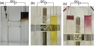
Figure 8. Photographs of aqueous solutions in H-shaped cells. (a) AgNP synthesis from Ag foil anodic dissolution induced by a cathodic microplasma. The plasma treatment time was 6 min and fructose was present in the solution to prevent agglomeration and precipitation of the particles [69]. (b) AgNPs and (c) AuNPs synthesized from aqueous solutions of AgNO3 and HAuCl4, respectively, using microplasmas as both the anode and cathode simultaneously. The plasma exposure time was 5 min [154]. Modified with permission from [69, 154], copyright 2010 IOP Publishing and copyright of the authors, respectively.
Download figure:
Standard image High-resolution imageRecently, Chen et al [71] synthesized AuNPs from an aqueous solution of HAuCl4 with deoxyribonucleic acid (DNA) as the capping agent by using a pulse plasma at a pressure of 20 KPa. The authors found that uniform-sized AuNPs could be formed rapidly when the plasma was irradiated on the solution. DNA can act as a capping agent for the formation of AuNPs by being electrostatically conjugated on the surface of the AuNPs. Two kinds of DNA were used based on their different adsorption energies on the Au surface, i.e. 30 mer DNA consisting of guanine or cytosine bases (denoted as dG30 or dC30). The results imply that the size and assembly of AuNPs can be tuned by the DNA type and concentration, as shown in figures 9(a) and (b), which subsequently modulates the spectroscopic properties of the AuNPs, i.e. tailoring the LSPR of the AuNPs. It is well known that Coulomb repulsion and van der Waals attraction exist between the metal NPs in the solution [157]. The imbalance between these two forces can cause NP growth by coalescence or NP self-assembly. The authors suggested that the DNA can tune the forces between the forming AuNPs by conjugating on the surfaces of the AuNPs. Depending on the concentration and type of the DNA, the final size and morphology of the AuNPs can be tuned, as illustrated in figure 9(d).
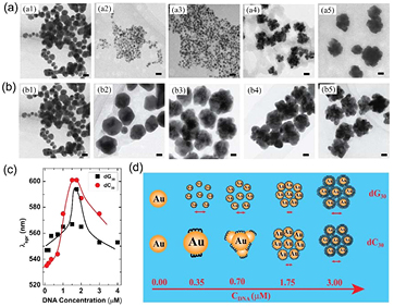
Figure 9. TEM images of AuNPs synthesized with 30 mer DNA consisting of (a) guanine (dG30) and (b) cytosine (dC30) with concentrations of 0, 0.35, 0.70, 1.75 and 3.00 µM for (a1) to (a5) and (b1) to (b5). The scale bar is 20 nm. (c) UV–vis absorption spectra of AuNPs synthesized with different concentrations of single-stranded dG30 and dC30. (d) A schematic of the final morphology tuned by DNA concentration and type. Modified with permission from [71], copyright 2012 Elsevier.
Download figure:
Standard image High-resolution imageAlthough the synthesis of metal NPs from aqueous solutions using plasma is very convenient, the high vapor pressure of water limits its use to plasmas operating at pressures from several tens of kPa to atmospheric pressure. Therefore, the plasma is limited to a small size which limits the yield of metal NPs. Thanks to ILs which have a very low vapor pressure, plasma–IL system operate at low pressures where traditional large-sized processing plasmas can be applied. Endres' group, co-working with Janek's group, performed the first AgNP synthesis by the method of reducing  dissolved in an IL of 1-butyl-3-methylimidazolium trifluoromethylsulfonate ([BMIm]TfO) [44, 45]. Subsequently, many studies have synthesized noble metal NPs from plasma–IL systems, such as the work by the groups of Endre [58, 158], Hatakeyama [43, 67, 148, 159–161] and Liu [47, 139, 162]. On one hand, NPs synthesized from a plasma–IL system do not need any additional surfactant to stabilize and their size can easily be tuned using the plasma parameters at low pressure. On the other hand, the conjugation of ILs on the surface of NPs is very difficult to eliminate when one wants to change the surface function of the NPs by changing the surface conjugated molecules. Most importantly, the solubility of many metal salts in ILs is lower than that in water, and to synthesize some metals we need a specific metal salt or specific IL to initiate the dissolution. The derivatives produced from the decomposition of the IL by plasma might contaminate the formed NPs. The reducing species generated from the plasma usually move more easily in water-based solutions than IL-based ones. Thus, we should address the above critical issues before we can intensively exploit plasma–IL systems for metal NP synthesis.
Plasma in liquid is also used in the synthesis of noble metal NPs. AuNPs have been synthesized by reducing  by plasma in aqueous solutions [48, 49, 163–166]. Without considering other mechanisms, Hieda et al [48], Sato et al [49] and Bratescu et al [164] considered that only the H radicals produced by the plasma act as the reducing species. Interestingly, Sato et al [49] investigated the dynamics of AuNPs formation during plasma ignition with time-resolved TEM. As illustrated in figure 10, the reduction of
  by plasma forms a loose self-assembly (100 nm or more) of small Au nanoclusters (less than 1 nm) at the very first stage, perhaps due to van der Waals attraction (not mentioned by the authors). In the second stage, with discharge plasma time lapses, the pH value of the solution decreases due to the major contribution of HNO3 formation from the interaction between the plasma and N2 as well as O2 dissolved in the solution and the minor contribution of water vapor decomposition
  At low pH values, the self-assembly of Au nanoclusters disassembles. Then the Au nanoclusters form spherical AuNPs (perhaps due to growth by coalescence) with smaller sizes than the previous assembly. The pH value decreases with increasing discharge time and when the pH value is lower than a critical value, the surface Au atoms of the formed spherical AuNPs are dissolved into the solution. This has been confirmed by measuring the time evolution of the
  concentration, which shows a valley-like shape. Finally, size-decreased spherical AuNPs as well as anisotropic AuNPs are formed in the solution due to the nonequivalent dissolution rate of different Au facets. In addition, based on the results of x-ray photoelectron spectroscopy, time-of-flight secondary ion mass spectrometry and UV–visible (UV–vis) absorption spectroscopy, Bratescu et al [164] found that the surfaces of synthesized AuNPs are partially oxidized when synthesized in solution with a pH value of 12, while the surfaces are surrounded by gold chloride compounds when synthesized in solution with a pH value of 3.
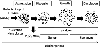
Figure 10. The dynamic process of AuNP synthesis from plasma in liquid. Reprinted with permission from [49], copyright 2009 Elsevier.
Download figure:
Standard image High-resolution imageIn addition to the use of chemical processes for NP synthesis in plasma–liquid systems, AgNPs [122, 123] and AuNPs [123] have been formed using evaporation of metal wires by discharge plasmas in electrolyte liquid or water. It was found that the type of liquid medium or composition can influence the particles' size and size distribution. Moreover, physical sputtering has also been used in a plasma–IL system. Torimoto et al [120, 121] first reported that AuNPs and Au/AgNPs can be formed by physical sputtering of a target Au or Au/Ag foil in a set-up as shown in figure 5. After these inspiring works, the physical sputtering method flourished in NPs synthesis [167–172]. The influence of sputtering conditions and IL composition on the final products has also been investigated. Hatakeyama et al [173] found that the size of NPs is independent of the discharge time, pressure and current, and the electrodes' distance, while it is strongly related to the target and IL temperatures, and discharge voltage. Wender et al [174] observed that the size and size distribution of NPs correlate with the IL structure, in particular with the surface composition of the IL, but are independent of the surface tension and viscosity. This sputtering method is suitable for almost all metals and can be used to synthesize metal NPs and alloys with tunable compositions. But, similarly to the NPs synthesized by chemical processes in plasma–IL systems, the resultant products might be contaminated by the IL and this problem must be overcome in future works.
3.2. Magnetic materials
Magnetic NPs, with both a nanoscale size and magnetism, offer exciting opportunities for a wide range of applications, including data storage [175], magnetic fluids [176, 177], catalysis [178], magnetic resonance imaging [179, 180] and biomedicine [181, 182]. In the last few decades, various approaches have been developed to synthesize magnetic NPs, including co-precipitation, thermal decomposition and/or reduction, micelle synthesis, hydrothermal synthesis and laser pyrolysis techniques [183]. Based on its low cost and the simplicity of its experimental set-up, the PLI method has recently demonstrated promise for the fabrication of magnetic NPs with a low cost and high speed.
NiNPs have been synthesized from discharge plasmas generated on a nickel cathode (immersed in  [184],
  [123] and NaOH [125, 185] solutions) and the NiNPs were observed in the solution as well as on the surface of the Ni cathode. A scanning electron microscope (SEM) image of NiNPs in the solution synthesized by Toriyabe et al [123] is shown in figure 11(a), showing a NP size of hundreds of nanometers with a relatively wide range distribution. Further investigation has suggested that the mean size of synthesized NiNPs decreases as the discharge voltage is increased. Subsequently, Akiyama et al [185] tuned the size of NiNPs by simply altering the solution (NaOH) concentration since the applied discharge voltage strongly depends on the solution concentration at a constant power input. Moreover, it was found that if the cathode was covered by a quartz glass tube, the size distribution and oxidation of the synthesized NPs were much suppressed (figure 11(b)). The authors attributed this to partial discharge on the cathode caused by the cathode covering, which limits the overheating of the Ni cathode [125].
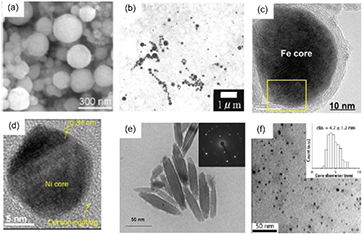
Figure 11. (a) SEM and (b) TEM images of NiNPs synthesized from Ni cathode evaporation in  and NaOH solutions, respectively. TEM images of (c) Fe@C NPs and (d) Ni@C NPs synthesized from PLIs in ethanol. (e) A TEM image of iron-related NPs synthesized from an aqueous solution of FeCl3·6H2O and polyethylene glycol. (f) A TEM image of FeOx NPs synthesized by multi-microplasma–liquid interaction. (a) Modified with permission from [123], copyright 2007 American Institute of Physics. (b) Modified with permission from [125], copyright 2011 Springer. (c) Modified with permission from [190], copyright 2011 Elsevier. (d) Modified with permission from [191], copyright 2013 The Japan Society of Applied Physics. (e) Modified with permission from [201], copyright 2011 Elsevier. (f) Modified with permission from [204], copyright of the authors.
Download figure:
Standard image High-resolution imageUsing pulse discharge plasmas generated between the tips of two corresponding Fe rods, micrometer γ-Fe synthesis has been reported in liquid ammonia [186] and iron carbide NPs (orthorhombic Fe3C and monoclinic  ) encapsulated by multilayered graphite sheets were also formed in ethanol by adding Ar gas and an ultrasonic cavitation bubble into the plasma zone [187, 188]. In an experimental set-up similar to [186], NPs of
  [189] and onion-like carbon-encapsulated Co, Ni and Fe (Co@C, Ni@C and Fe@C) [190, 191] were fabricated from aqueous solutions of cationic surfactant (1-hexadecylpyridinium bromide monohydrate, CPyB) and ethanol, respectively. This fabrication method takes advantage of both anodic dissolution and cathode evaporation as mentioned in section 2 and the yield should be enhanced in contrast to the process which only uses either anodic dissolution or cathode evaporation. The utilization of a cationic surfactant and ethanol allows surface modification, resulting in the tailoring of the size, stability and oxidation of NPs. Due to the coexistence of reducing and oxidizing species at the plasma–liquid interface, the resultant NPs should be a mixture of pure metal and metal oxidation. The authors of [189] also found that the
  NPs (~19 nm) were a mixture of Fe, FeO and
  and the purity of
  increased with increasing CPyB concentration. A purity of 98% for
  NPs can be obtained in an aqueous solution of CPyB (0.84 g in 200 ml distilled water). TEM images of Fe@C and Ni@C synthesized from ethanol are shown in figures 11(c) and (d), respectively. The synthesized NPs are coated with a few layers of carbon, formed from the carbon precursors produced by plasma-induced ethanol decomposition. Interestingly, the results of x-ray diffraction (XRD) and energy-dispersive x-ray (EDX) spectroscopy of the NPs indicate that there was no observable oxidation of the core metal. This non-oxidization of NPs might be due to the presence of ethanol which can scavenge the plasma-induced strong oxidizing species of OH radicals and generate reducing species (H and H2) as described in equation (6) [192, 193],


By encapsulating magnetic NPs in carbon, the NPs showed high coercivities: 296 Oe for Fe@C and 189 Oe for Ni@C, compared to those of bulk Fe (90 Oe) and Ni (70 Oe) [191]. (The unit of coercivity was mistaken as T in [191], we correct it to Oe in this review.) In addition, the results of the exposure of human lung epithelial A549 cells to Fe@C, Co@C and Ni@C NPs show a low cytotoxicity of these NPs [190]. Their high magnetic properties and low cytotoxicity make these NPs possible candidates for manipulation in biomedical applications. Pure FeNPs (>100 nm) [194] and pure CoNPs (>90 nm) [195] were also reported to be generated in an arc discharge over a liquid of ethylene glycol with two Fe or Co electrodes, where the ethylene glycol might play the same role as ethanol in [190, 191]. Using the molten salt LiCl–KCl–CsCl (over 300 °C) as the solution, FeNPs [196], CoNPs [197] and NiNPs [198–200] were synthesized from the dissolution of corresponding metal anodes under plasma exposure to the molten solution. However, the high processing temperature leads to a broad size distribution. To control the size and size distribution, a disk anode was rotated. This can change the plasma exposure spot with rotation, decreasing the delivered quantity of reducing species onto the exposed spot [198]. As a result, smaller sized NPs and a more uniform size distribution can be obtained with a higher speed rotation of the anode.
In addition to the consumption of the electrodes, the solution is also used as a precursor to synthesize magnetic NPs as in the aforementioned case of AuNP synthesis. Figure 11(e) shows rice-shaped NPs which were synthesized from an aqueous solution of  and polyethylene glycol with a pulse plasma generated between two tungsten electrodes [201]. The XRD pattern of these NPs indicates that the NPs consisted of
  and iron oxide-hydroxide (β-FeO(OH)). The formation of Co (0) [202] and Co (II) oxide [203] NPs was reported in experimental set-ups similar to [201] by simply replacing the solution with aqueous solutions of
  and sodium dodecyl sulfate or
  The conclusion of the formation of pure CoNPs needs to be re-examined due to the reactivity of cobalt and the presence of strong oxidizing species.
FeOx NPs can also be rapidly synthesized by atmospheric-pressure multi-microplasmas generated over an aqueous solution of FeCl2, dextrane and dimercaptosuccinic acid [204]. The plasma acts as the cathode, while a graphite rod immersed in the solution is used as the anode. The as-synthesized FeOx NPs were purified by removing the excess of ions and ligand molecules using dialysis or size exclusion chromatography. Ultra-fine FeOx NPs (≤5 nm) with a narrow size distribution were obtained after the purification process, as shown in figure 11(f). Rudimentary magnetic resonance imaging assessments confirmed the 'positive' contrast enhancement effect when the synthesized FeOx NPs were used as the contrast agent.
3.3. Cu
CuNPs with controllable shapes have shown significant catalytic [205], optical [102, 206] and conducting properties, from which many fundamental and technological research fields might benefit. However, Cu is very reactive when its size decreases to nanometers. It is difficult to fabricate pure metallic CuNPs using a solution-based process without very strong reducing agents and a carefully selected protective capping material. In order to avoid possible oxidation from the ambient, the strong reducing agent of hydrazine has been used in the synthesis of pure metallic CuNPs [207, 208].
As we found in section 2, PLIs can simultaneously generate strong reducing species as well as strong oxidizing species in aqueous solutions. One might consider that it is infeasible to synthesize pure metallic CuNPs from PLI and, with or without unsuitable capping agents, many efforts have produced partially oxidized CuNPs [58, 209–213]. However, the formation of CuNPs from PLIs might be possible if we select appropriate capping agents and note the competition between the reducing and oxidizing species generated from the PLIs. Progress has already been made in the selection of suitable protective capping agents [214–216].
CuNP synthesis has been performed in an atmospheric-pressure ac plasma generated between two Cu rods (one over and the other in the aqueous solution) [214]. The authors found that the utilization of pure deionized water leads to the formation of spindle-like Cu2O/CuO nanostructures, while a solution of ascorbic acid or a mixture of ascorbic acid/cetyltrimethylammonium bromide (CTAB) results in the formation of metallic CuNPs, which was attributed to the protective effect of ascorbic acid on the nascent Cu seeds. Interestingly, as shown in figure 12(a), the surfactant CTAB showed a critical influence on the self-assembly of spherical CuNPs (with diameters of 700 nm–1 mm). Under reduced pressure (30 Torr), spherical CuNPs can also be formed from a pulse discharge plasma generated between two Cu rods immersed in pure ethylene glycol, whereas when deionized water was mixed with ethylene glycol, the products became needle-like CuO, polygon Cu2O and square Cu2O NPs depending on the water content [215]. These different morphologies were ascribed to the influence of the different thermal conductivities of the liquids used in the formation process of the NPs.
Figure 12. (a) A TEM image of a self-assembly of CuNPs synthesized from PLIs in an aqueous solution of ascorbic acid/ CTAB. (b) TEM images of the anisotropic shapes of CuNPs synthesized from an aqueous solution of ascorbic acid/gelatin/CuCl2 with a 10 min treatment. (a) modified with permission from [214], copyright 2004 Elsevier. (b) modified with permission from [216], copyright 2013 IOP Publishing.
Download figure:
Standard image High-resolution imageInstead of consuming the electrode material, CuNPs formation from PLIs by reduction of dissolved metal ions has also been reported [216]. An aqueous solution of ascorbic acid/gelatin/CuCl2 was used as the Cu source and the NPs were formed from a pulse discharge plasma generated between two tungsten electrodes submerged in the solution. XRD results of the products indicate a decrease in oxidization with increasing discharge time. Based on thermogravimetric analysis, the authors assumed that the gelatin played an important role in protecting the CuNPs. As the discharge time increased, the gelatin fractions produced by plasma decomposition and the solution temperature were increased, while the pH value was decreased. Thus, the synthesized CuNPs were protected due to the scavenging oxidizing species of the gelatin fractions [217] together with the relaxation of the random coil of gelatin [218] at low pH values and high temperatures. Figure 12(b) shows the synthesized multi-shaped CuNPs. It is worth noting that the CuNPs are polydisperse rather than monodisperse colloids. Future work should pay attention to the formation of shape-controlled monodisperse CuNPs for advanced applications.
3.4. Metal oxides
In contrast to the pure metallic NPs of reactive metals, the formation of corresponding metal oxides from PLIs is relatively easy due to the existence of strong oxidizing species. Various kinds of metal oxide NPs fabricated from PLIs have been reported [61, 219–234]. In the following, we will give two representative results for PLI-induced metal oxide NPs.
An ac plasma was generated between a Cu filament and an aqueous solution of NaNO3 and another Cu filament was immersed in the solution as the counter electrode [233]. The Cu ions came from the anodic dissolution of the immersed Cu filament and the evaporation of the other Cu filament and reducing species generated by PLIs reduced these Cu ions to form NPs. Figure 13 shows TEM images of products obtained from this ac plasma over liquid system. As shown in section 3.3, the oxidation state of the final products depends on the available capping agents. Without any surfactant, the as-synthesized products were small CuO particles and grew into rice-shaped CuO nanorods (figures 13(a) and (b)). However, the small products grew into Cu2O NPs or CuNPs when ascorbic acid or hydrazine hydrate were added into the NaNO3 solution. One possible explanation is that the oxidizing species produced by PLIs can be scavenged by the additives and the different abilities of the scavengers result in different oxidation states of the products.

Figure 13. TEM images of products from PLIs after synthesis of (a) 30 min for CuONPs, (b) 1 week for CuONPs, (c) 2 weeks for Cu2ONPs and (d) 2 weeks for CuNPs. The PLIs were performed by generating an ac plasma over an aqueous solution of NaNO3. Two Cu filaments were used as the electrodes (one over and the other inside the solution). There was no additive in the solution for CuONP synthesis, but ascorbic acid or hydrazine hydrate were added to the solution for the Cu2ONP and CuNP syntheses. Modified with permission from [233], copyright 2005 American Chemical Society.
Download figure:
Standard image High-resolution imageZnONPs can also be formed from plasma in liquid [234]. A Zn wire (as the cathode) and a mesh made of Pt wire (as the anode) were submerged in an aqueous solution of  When a certain voltage was applied, plasma was generated at the immersed part of the Zn wire. A medium power input resulted in the formation of flower-like ZnONPs (figures 14(a) and (b)), while a high power input lead to the formation of aggregated ZnONPs (figure 14(c)). Figure 14(d) presents the mechanism of the synthesis. The Zn wire is oxidized to ZnO on its surface after plasma generation. At a low power input, the surface is below the melting point and some
  can be formed around the Zn wire through the reaction
 and then the
  transfers to the low temperature zone and decomposes into ZnO through
 These ZnOMPs grow preferentially along the [0 0 0 1] direction [235, 236] to form flower-like ZnONPs. However, at a high power input (>300 W cm−2, data taken from [234]), the temperature of the Zn wire reaches its melting point. Rapid evaporation supplies Zn and ZnO, resulting in the aggregation of ZnO particles, as shown in figure 14(c).
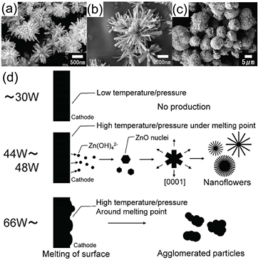
Figure 14. SEM images of products obtained from plasma inside liquid, under the experimental conditions of  concentration and discharge voltage/power of (a) 1.0 M, 66 V/44 W, (b) 0.5 M, 80 V/48 W and (c) 0.01 M, 200 V/168 W. (d) A schematic of ZnO synthesized from plasma in liquid. Modified with permission from [234], copyright 2011 Elsevier.
Download figure:
Standard image High-resolution image3.5. Alloys
It is well known that NMs usually lack stability due to their large volume fraction of grain boundaries. In addition to surface functions using various ligands, the alloying of NMs is one alternative strategy for stabilizing NMs [237, 238]. The metal can come either from the electrode materials or from the working solutions. In this manner, PLIs can also be used to fabricate alloying NMs.
A displacement reaction has been used to synthesize FePt [196, 239]. FeNPs were first formed from an Ar plasma-induced cathodic discharge generated over molten FeCl2/LiCl–KCl–CsCl (573–773 K) and then PtCl2 was added to the FeNP dissolved molten solution. Continuous plasma treatment lead to the displacement reaction of  then a process of later solid phase interdiffusion resulted in the formation of FePt (~100 nm). In fact, the XRD data indicate that the first-step synthesized FeNPs were actually dominated by the
  phase and the final products were a mixture of Fe/Pt/FePt/
 The authors suggested that the oxidation of the FeNPs confirmed by the XRD data was probably caused by the water washing process during the extracting period. Presumably pure
  NPs can be obtained by optimizing the ratio of FeCl2 to PtCl2 and the discharge time. The synthesis of CoPt [197, 198], CoPt3 [197] and SmCo [240] NPs using a similar method was also reported.
By generating a dc plasma between an  plate anode and an Fe rod cathode (both immersed in ethanol), FePt alloy NPs with broad size distributions from several to several hundreds of nanometers were synthesized [241]. An ultrasonic system was used to produce cavitation bubbles between the electrodes to facilitate the discharge. Therefore, the resultant products were formed by plasma discharge in liquid ethanol with an ultrasonic cavitation field. Based on XRD and TEM analyses, the authors concluded that the products were carbon encapsulated and most of the cores had an average composition of paramagnetic
  Figure 15 presents the hysteresis loops of the (a) as-synthesized and (b) 923 K annealed carbon encapsulated Fe–Pt alloy NPs. For the as-synthesized product, the coercivity is 6.4 k Am−1 and the magnetization saturation is 16.7 Am2 kg−1 at room temperature. The coercivity and the magnetization saturation change to 73.6 k Am−1 and 13.5 Am2 kg−1, respectively, after 923 K annealing. The small decrease of magnetization was accounted for by the possible redistribution of chemical elements (Fe–Pt) during the annealing (toward Pt-rich composition), and the coercivity change was related to the conversion of the disordered fcc structure to the ordered fct structure, as confirmed by XRD analysis.
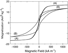
Figure 15. Hysteresis loops of the (a) as-synthesized and (b) annealed (at 923 K) Fe–Pt NPs synthesized from PLIs operating from a  plate anode and a Fe rod cathode in ethanol. Modified with permission from [241], copyright 2010 Springer.
Download figure:
Standard image High-resolution imageBimetallic Ag–PtNPs were also reported to be formed by a unipolar pulse plasma between a Ag cathode and a Pt anode in an aqueous solution of sodium dodecylsulfonate (SDS, 10 mM) and NaCl (0.1 M) [242]. The reducing species produced by the plasma reduce the Ag and Pt ions coming from the electrodes, resulting in the formation of Ag–Pt NPs in the solution. Figure 16(a) shows a TEM image of the Ag–PtNPs fabricated by 30 s plasma treatment. The NPs have a narrow size distribution with an average size of 5 nm. A high-resolution (HR) TEM image and selected area electron diffraction (SAED) patterns of the synthesized Ag–Pt are presented in figures 16(c) and (d). These HR TEM and SAED results indicate that the bimetallic NPs were in the form of an immiscible nanocomposite with a distinct boundary between the phases of Ag and Pt. Thus, the synthesized NPs were Ag–Pt bimetallic NPs rather than a usual alloy. Similar to this work, wurtzite-type ZnMgS synthesis was reported from a pulse plasma generated between two ZnMg rod electrodes inside liquid sulfur [243].

Figure 16. (a) A TEM image of Ag–PtNPs, (b) a HR TEM image showing many small islands of Pt (dark areas) on a layer of Ag and (c) the SAED patterns of the fcc plane reflection of Ag–PtNPs. The NPs were synthesized from a unipolar pulse plasma generated between a Ag cathode and Pt anode in an aqueous solution of sodium dodecylsulfonate (SDS, 10 mM) and NaCl (0.1 M). The discharge time was 30 s. Modified with permission from [242], copyright 2012 IOP Publishing.
Download figure:
Standard image High-resolution imageIn addition to using the chemical processes in PLIs, the physical sputtering process can also be used to synthesize alloy NPs, such as AuAg [121, 244, 245] and AuPd [246] by using the experimental set-up as shown in figure 5. The alloy can be formed by sputtering a multi-metal-composed target with Ar plasma at a low pressure. The sputtered metal clusters are collected by the IL just below the target. The IL provides a nucleation and growth field for the clusters and also acts as a stabilizing agent for the formed NPs. Because it is simple to change the target, there is potential to extend this method to the synthesis of various metal alloys.
3.6. Semiconductors
Since semiconductor quantum dots (QDs) were discovered by Ekimov et al [247] in the early 1980s, they have attracted much attention due to their size- and shape-dependent electronic and optical characteristics. These unique properties render QDs suitable for versatile applications such as in transistors, solar cells, LEDs, diode lasers, medical imaging and quantum computing [248–255]. Stimulated by these promising applications, many approaches have been developed to synthesize semiconductor QDs [256, 257].
In principle, it is also possible to form semiconductor QDs using PLIs. However, there are only a few reports on semiconductor QD synthesis by PLIs. This is partially due to the fact that it is difficult to find suitable liquid precursors containing semiconductor elements, for example, many Si-containing liquids are unstable and sometimes toxic. Therefore, suitable precursors are limited.
Silicon electrodeposition on a substrate has been reported using Si-containing organic solutions [258, 259], ILs [260, 261] and molten salts [262–264]. Thus, semiconductor QDs can also be formed if the substrate in the electrodeposition system is replaced by a gaseous plasma. In fact, efforts have been made to synthesize Si and Ge [58, 265, 266] QDs in a low-pressure plasma–IL system, and TEM images of the synthesized SiQDs and GeQDs from three types of ILs are presented in figure 17. The results indicate that the size of SiQDs and GeQDs are similar when using 1-ethyl-3-methylimidazolium bis(trifluoromethylsulfonyl)imide ([EMIM]Tf2N), while the size of GeQDs is dramatically decreased when using 1-Ethyl-3-methylimidazolium tris(pentafluoroethyl)trifluorophosphate ([EMIM]FAP). The authors did not explain this phenomenon. Probably, the anions of Tf2N and FAP can serve as capping ligands [267] for the synthesized QDs and this assumption can be tested by EDX mapping of the QDs.
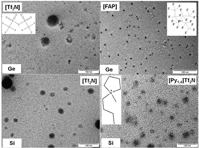
Figure 17. TEM images of SiQDs and GeQDs synthesized from a low-pressure plasma–IL system. SiCl4 and GeCl2 dissolved in ILs served as the anode. The ILs were 1-ethyl-3-methylimidazolium bis(trifluoromethylsulfonyl)imide ([EMIM]Tf2N), 1-butyl-1-methyl-pyrrolidinium bis(trifluoromethylsulfonyl)amide ([Py1,4]Tf2N) and 1-Ethyl-3-methylimidazolium tris(pentafluoroethyl)trifl uorophosphate ([EMIM]FAP), and the structures of Tf2N, FAP and [Py1,4]Tf2N are displayed in the image. Reprinted with permission from [265], copyright 2013 Elsevier.
Download figure:
Standard image High-resolution imageStrangely, there are no reports of SiQD synthesis by the PLI-induced reduction of Si-containing aqueous solutions, although there are strong reducing species with an E° as high as −2.87 V (table 1) in PLIs. Due to the strong reducing species, reactions such as  (E° = −1.37 V [268]) and
  (E° = −0.99 V [90]) are possible in PLIs and SiQDs might be formed from these reactions. In addition, it is possible to use ILs as a flexible substrate for synthesizing SiQDs in low-pressure plasmas, since Si sputtering [269, 270] and the decomposition of Si-containing gas or liquid precursors [271–276] are feasible.
3.7. Novel carbon-related materials
In the early 1990s, a method based on arc discharge induced carbon evaporation was developed for producing C60 [277] in He and multi-walled carbon nanotubes (MWCNTs) [278] in Ar. This method was later modified to produce a variety of polycyclic aromatic compounds [51, 279] and C60 [51] by generating an arc discharge plasma between two graphite [279] or pyrographite [51] electrodes in liquid toluene. It was believed that the precursors used to form the products originated from graphite electrode erosion for a low dc discharge voltage (24–28 V) [279], while for a high ac discharge voltage (10–20 kV), the precursors seemed likely to have originated from both the decomposition of toluene and the erosion of the electrode [51].
Stimulated by their unique properties and the great number of potential applications for novel carbon-related NMs, the simple method of a discharge plasma in liquid was used in many experiments in the last few decades. By simply modifying some part of the prototype, success has been achieved in producing MWCNTs [280–283], carbon onions [52, 284–286], carbon nano horns [287, 288], carbon NPs [117, 118, 289–295] and graphene nanosheets [117, 296–299]. An example is presented in figure 18. Two graphite electrodes were submerged in deionized water and a discharge voltage of 16–17 V (30 A) was applied to the electrodes. A discharge plasma was generated in the water by decreasing the electrodes' gap to certain distance as shown in figure 18(a). Figures 18(c) and (d) present low-resolution (LR) and HR TEM images of the products floating on the water surface. The products clearly consist of spherical carbon onions as well as polyhedral, nested, onion-like particles. Since the water was used as the discharge medium, the products must be formed from the precursors produced by the interactions between the plasma and electrodes. The synthesized novel carbon onions might be beneficial for potential applications such as solid-state lubrication [52] and supercapacitors [53].
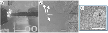
Figure 18. (a) A photograph of an arc discharge in water for producing carbon onions, the scale bar is 12 mm. (b) LR and (c) HR TEM images of the formed carbon onions, the scale bar is 10 nm. Samples were taken from the floating material on the water surface after their production. Reprinted with permission from [52], copyright 2001 Nature.
Download figure:
Standard image High-resolution imageMore recently, nanodiamonds have been obtained from an atmospheric-pressure microplasma operated in the gaseous phase of Ar/H2/ethanol [300]. This result suggests that it is possible to fabricate nanodiamonds from a microplasma generated over or inside liquid ethanol, although no relevant report has been published so far. Therefore, we should pay more attention to microplasma–liquid ethanol systems; perhaps nanodiamonds can also be produced by this system by optimizing the plasma parameters.
4. Perspectives on future research
The prospects of NM synthesis by PLIs are promising and exciting as they offer the rapid and easily controllable synthesis of a variety of NMs. However, there are several issues that must be addressed in future works. These include: (1) size- and shape-controlled synthesis, (2) oxidization prevention for reactive metals and (3) removal of impurity materials and large-scale production.
4.1. Size- and shape-controlled synthesis
The physical and chemical properties of NMs are closely dependent on their size and shape, and therefore size- and shape-controlled synthesis of NMs is great of importance [39]. Reports on the size-controlled synthesis of NMs from PLIs have been presented [49, 72, 143, 164, 185, 301–304], while reports on shape-controlled synthesis are scarce, and even the few reported shape-controlled syntheses lead to a mixture of NMs with several shapes [49, 136]. To advance this field of research, the size- and shape-controlled synthesis of NMs from PLIs is necessary. We can address this subject from two directions: the liquid and the plasma.
Solution-based NM synthesis has provided us with ample strategies for size- and shape-controlled synthesis. The formation of NPs in a solution is illustrated in figure 19 [305] based on the theory of LaMer and Dinegar [306]. The solute is the feedstock for the NPs, say, Aun (n ≥ 1) formed by reducing an aqueous solution of HAuCl4 with a reductant. The solute concentration builds up as the reduction reaction proceeds. When the solute concentration reaches a critical value, the system becomes heterogeneous by a process of nucleation. The rate of nucleation depends on the solute concentration at which the system starts to nucleate. The number of formed nuclei increases with time and consequently results in a rapid decrease of solute concentration. When the solute concentration is below the critical concentration, nucleation stops and NP growth begins. If there is no surfactant, the formed NPs will finally aggregate to reduce the free energy of the system. This mechanism provides us with a route to obtain size-controlled monodisperse NPs. If the amount of precursors is constant, the final size of the formed NPs is related to the number of nuclei, which can be changed by tuning the nucleation time using the reducing speed and the reaction temperature.
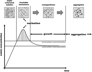
Figure 19. An illustration of the nucleation and growth of NP formation in a solution. Reprinted with permission from [305], copyright 2004 The Royal Society of Chemistry.
Download figure:
Standard image High-resolution image
It is well known that the rate of chemical reaction is related to the temperature, pH value, etc. Thus, the rate of nucleation might be tuned by the reaction environment, such as the ratio of reactants, the temperature and the pH value. In fact, the effect of temperature has been shown in a H2/He plasma–aqueous  solution [42] and by sputtering a gold electrode with a discharge plasma in liquid nitrogen and water (0 °C) [302, 307]. The former case showed that the sizes of the synthesized PtNPs were 2 and 5 nm at temperatures of 10 and 40 °C, respectively. Similarly, the sizes of the formed AuNPs in the latter case were ~1.5 nm in liquid nitrogen and ~3.5 nm in water, and these sizes are obviously smaller than those in the similar works performed at room temperature (sizes usually >10 nm). In addition, the size and assembly of NPs synthesized from PLIs can also be tuned by the choice of surfactant type and concentration [71].
The seed-mediated [41, 308], plasmon-mediated [309] and template-based [310–312] growth of anisotropic NMs are popular techniques in solution-based processes. The electrochemical method also has the possibility of synthesizing gold nanorods [102, 313, 314]. It has been found that surfactants play an important role in adjusting the growth rate of different facets of NMs, for example, CTAB is usually present in gold nanorod synthesis [315]. Thereby, we can apply these valuable strategies to the synthesis of anisotropic NMs from PLIs, since the PLI method is just a modified solution-based system, by replacing the reducing agents with PLI-induced species. Moreover, the formation of gold nanorods from PLIs [160] using CNTs as templates proves the feasibility of these concepts.
Differing from solution-based synthesis, the plasma-induced reducing species are usually not of only one type but several, as discussed in section 2. The difference in reducing ability of the species in PLIs provides us with a way to tune the nucleation and growth of NMs by varying the plasma parameters. For example, in a plasma over a HAuCl4 dissolved IL system, when a negative voltage was applied to the IL, small-sized AuNPs were obtained, while large-sized AuNPs were formed when a negative voltage was applied to the counter electrode [159]. It was understood that the yields of the reducing species induced by the PLIs were changed by changing the voltage polarity. The discovery of the short- and long-lived reducing species in plasma–aqueous solution systems [71] allows us to optimize the discharge time, by which the rates of nucleation and growth as well as the after plasma ageing growth might be controlled. Our own work has also indicated that the shape of the synthesized AuNPs can be tuned by the discharge time in a plasma over an aqueous solution of HAuCl4/DNA (unpublished, 30 mer DNA consisting of guanine bases). Apart from the discharge time and voltage, other parameters such as gas atmosphere and pressure can also be used to adjust the yields of reducing species. For example, if we use  or ammonia as the working gas, ample atomic hydrogen and some hydrazine
  [97] will be produced by the plasma and the components of the reducing species will be different from an Ar plasma–liquid system. As a result, the nucleation and growth of NPs in the solution will be changed by changing the gas atmosphere. At present, there is still a large demand for plasma-parameter-induced size- and shape-controlled synthesis of NMs, which will become of even greater interest in the future.
4.2. Oxidization prevention for reactive metals
As described in section 2, the interactions between a plasma and an aqueous solution can produce reducing species and, at the same time, oxidizing species. Therefore, in order to synthesize NPs of pure reactive metals such as Fe, Cu and Zn, oxidization in the process should be prevented by method. Surface coating using an inertial material is one simple means by which the coated NPs become oxidant resistant, stable and safe if used in vivo. The coating can be carried out by using either a carbon-rich liquid or a carbon electrode in the PLIs [190, 191]. It is also possible to protect the NPs by eliminating the oxidizing species in PLIs using an oxidizing species scavenger either produced by the PLIs themselves or from an outside additive. Moreover, the stability of NPs can be increased by alloying them with other metals [237, 238, 316–318] and, at the same time, specific properties such as strong catalytic ability can be achieved. We should point out that it is possible to synthesize NPs of pure reactive metals if the working gas for the discharge plasma is oxygen free and if the liquid is oxygen free or a molten metal salt, but the synthesized NPs are still very susceptible to oxidation from oxygen in the surroundings when they are transferred.
4.3. The removal of impurities and large-scale production
Impurities can enter the final products during NM synthesis from PLIs in several ways. If the NMs are formed from the metal ions in the solution, undesirable impurities may arise from the electrode through chemical reactions, physical sputtering, or evaporation. The parameters for controlling these effects are usually specific to an individual experimental set-up. Therefore, extensive research is required to find the optimal conditions to prevent or decrease the impurities based on the physics and chemistry underlying the plasma–liquid system.
It is suggested that a preliminary attempt should involve the electrode design. Coating the electrode with an inertial material such as carbon or quartz might be useful to prevent some liquid-based chemical reactions at the electrode. This method must use a pulse, radio frequency power or dc source with a high voltage. Alternatively, the impurities from the electrodes can be excluded if an electrodeless discharge plasma (such as an inductively coupled plasma) is used.
The formation of NMs from PLIs containing surfactants is inevitably accompanied by the decomposition of surfactants. The resulting fragments of surfactants as impurities might have a positive or negative effect on NM formation, which should be carefully studied.
In addition, plasmas used in PLIs are usually operated at atmospheric pressure or several tens of kPa, the sizes of the plasmas are limited to several millimeters, at least in one dimension, due to Paschen's law. For large-scale production of NMs from PLIs, the plasma area should be increased. The recently developed plasma arrays [22, 319–324] might be a good choice since the plasma area is greatly increased by integrating many microplasmas into one array. We can also use other large-area atmospheric-pressure plasmas [325–333] which are based on different designs. Although the plasma area can be relatively large in a plasma–IL system at low pressures, the dissolution rates for most metal salts are smaller in ILs than those in aqueous solutions, which limits the application of the plasma–IL systems in the large-scale production of NMs.
5. Conclusions and outlook
In this review, we have summarized the recent advances and current conditions of the NM synthesis from PLIs. A theoretical analysis of the NM synthesis process is presented by analyzing experimental data. In addition to the theoretical analysis, practical applications of PLIs in several NM synthesis methods are also presented.
A discharge plasma making contact with a liquid provides a plasma–liquid interface where many physical and chemical processes take place. These processes includes decomposition, sputtering, and evaporation of the liquid and the electrode materials, producing complicated reactants including reducing as well as oxidizing species, and NMs can be formed by reactions between the reactants and the precursors originating from either the liquid or the electrodes. In particular, reducing and oxidizing species produced by plasma–aqueous solution interactions are summarized: long- and short-lived reducing species exist and their reducing abilities are roughly in scale with their standard reduction potentials. These findings indicate that it is possible to control NM nucleation and growth by tuning the yields and ratios of the yields for different reducing species. In addition to the utilization of chemical processes, physical processes, such as electrode sputtering and evaporation, are also presented for PLIs. Moreover, a wealth of data is provided for PLI applications in NM synthesis ranging from noble metals to graphene nanosheets. The solid experimental data and theoretical analysis suggest that the PLI method is a fascinating alternative for synthesizing various NMs.
To improve the application of NMs synthesized from PLIs, the physical and chemical properties of the NMs should be tuned following the different requirements of various application environments. This aim can be achieved by tuning the size and shape of NMs. PLIs provide a larger parameter space compared with solution-based synthesis, that is, both the solution and the plasma, from which we can tailor the size and shape of NMs by tuning the nucleation and growth processes. The tailoring of plasma parameters allows us to control the yields of different reducing species, thus controlling the final size and shape of the NMs.
Although much has been achieved in the PLI-induced synthesis of NMs to date, the detailed spatial and temporal evolutions of the processes taking placing in the solution, the plasma–liquid interface and the bulk plasma are still not well understood. Therefore, in situ probing is required to disclose the underlying secrets of PLI-induced synthesis. After determining the detailed processes, we should be able to elaborately tune the specific reactions in PLIs by changing the corresponding parameters and finally obtain NMs with desirable sizes and shapes.
Furthermore, as past works have mainly focused on the synthesis of NMs from PLIs, more detailed studies need to be implemented on monodisperse synthesis and the property diagnostics for advanced applications of synthesized NMs in catalysis, solar cells, biomedicine, etc.
Acknowledgments
This work was partially supported by the National Natural Science Foundation of China (Grant Nos: 11405144, 11304132, 61376068 and 21322609), the Science Foundation Research Funds Provided to New Recruitments of China University of Petroleum, Beijing (QZDX-2014-01) and the Thousand Talents Program. QC is greatly indebted to Dr Marc-André Fortin of Université Laval and Dr Naoki Shirai of Tokyo Metropolitan University for their kind permission to reprint their TEM images.