
Abstract
Single- and four-core MgB2 wires have been manufactured by internal magnesium diffusion (IMD) into boron. Initial hydrostatic extrusion was applied for single-core Cu sheathed wire and mostly rolling deformation for assembled four-core wires with Inconel or GlidCop sheath. The highest critical current density (Jc) was measured for the wire with boron densified by cold isostatic pressing by 1.9 GPa. Rolled tapes have exhibited critical current anisotropy increasing with the tape's aspect ratio. Low critical current degradation of IMD wires by twisting has been observed, which can be utilized for effective reduction of AC losses. High engineering current densities of IMD wires are promising for the generation of magnetic fields between 1 and 3 T at cryogen-free conditions, which can be utilized for future MRI systems or wind power generators.
Export citation and abstract BibTeX RIS
1. Introduction
There are several technological processes which can be applied for the manufacture of composite MgB2 wires [1–5]. The commonly used powder-in-tube (PIT) technique has several approaches differing in the initial precursor powder used: (i) in situ (Mg + B) [1], (ii) ex situ (MgB2) [2], (iii) mechanical alloying (Mg + B + MgB2) [3] and (iv)MgB4 + Mg [4]. Giunchi et al have introduced the so-called 'magnesium liquid infiltration' process using B powder surrounding the central metallic Mg rod [5]. The core density of ex situ MgB2 wires is influenced dominantly by the applied sheath material, fill factor and used deformation. It can reach maximally 90% of the theoretical one (2.6 g cm−3) [6]. High core porosity is typical for the in situ route due to the volume shrinkage during the transformation of the Mg + B mixture into MgB2 compound. The volume ratio of (VMg + 2VB)/VMgB2 is 1.3, which corresponds to a ∼30% volume reduction during the in situ process [7]. Therefore, several new techniques allowing higher filament densities of MgB2 wires were tested recently [4, 8–10]. Wires fabricated by internal Mg-diffusion are characterized by dense and compact MgB2 core with considerably higher current density than the wires prepared by the in situ process [8]. Consequently, they make higher engineering current densities possible, which is important for future applications [9].
This contribution presents selected electrical and mechanical properties of MgB2 wires made by internal magnesium diffusion into boron.
2. Experimental details
Pure Mg wire of 2.9 mm in diameter surrounded by B powder of 99% purity inside a 5/7.5 mm Ti tube was rotary swaged to 6.5 mm and then inserted into the Cu tube of 6.7/9.15 mm. Initially, the assembled billet was isostatically pressed (CIP by 1.77 GPa/15 s) and then hydrostatically extruded (HE) from 9.0 mm composite into 6.0 mm wire. Extruded wire was then two-axially rolled (TAR) to the size of 4.2 × 4.2 mm2, heat treated at 300 °C/45 min and groove rolled down to 1.08 × 1.08 mm2 (named IM1Cu wire) [11]. In addition, two short samples of IM1Cu wire were isostatically pressed by 1.9 GPa and rolled to tapes of thickness 0.69 mm and 0.48 mm having the aspect ratio (b/a—width to thickness) of 2 and 3, respectively.
Two types of four-core wires have been assembled from as-rolled IM1Cu wires. One of 1.38 × 1.38 mm2 inserted into Inconel 600 tube of 4/5 mm (IM4Inc) and the second of Cu etched IM1Cu wires of 1.3 × 1.3 mm2 assembled into GlidCop AL-25 tube 3.2/4.5 mm (IM4Gli). The four-core wires were then rolled down to ∼1.0 mm size. One piece of IM4Gli wire was drawn to the diameter of 0.86 mm and subjected to twisting with variable twist pitches. Short wire samples (≈70 mm) were finally heat treated (HT) at 640 °C/1 h in pure Ar. Optical microscopy and Vickers microhardness measurements HV0.05 (5 g, 20 s) were used for cross-sectional study of the HT wires. The following fill factors (% of MgB2) were measured after HT in IM1Cu (figure 1(a)), IM4Inc (figure 1(b)) and IM4Gli (figure 1(c)): 9.4, 5.7 and 7.5%, respectively.
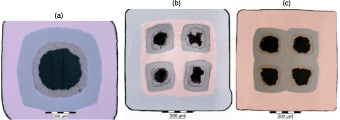
Figure 1. Cross-section of heat-treated single-core MgB2/Ti/Cu wire (IM1Cu) of 1.08 × 1.08 mm2 (a), four-core MgB2/Ti/Cu/Inconel (IM4Inc) 1.0 × 1.0 mm2 (b) and MgB2/Ti/GlidCop (IM4Gli) of 0.94 × 0.94 mm2 (c).
Download figure:
Standard image High-resolution imageMagnetic measurements were performed for single-core wire (≈5 mm) in a 14 T physical property measurement system with vibrating sample magnetometer (PPMS-VSM) with field direction longitudinal to the wire axis and temperatures between 4.2 and 25 K. Critical current density was determined from the hysteresis loops, recorded with sweep rate of 6 mT s−1, using Bean's formula [12]. Transport critical currents were measured at liquid He temperature and external field between 3.5 and 8.0 T using the 1 μV cm−1 criterion. Moreover, multi-pulse current measurement was used for the short samples between 4.2 and 20 K [13]. AC loss measurements were performed on untwisted and twisted IM4Gli wire by the calibration-free method at the temperature range 18–40 K, constant frequency of 72 Hz and external magnetic field of 37 mT in RMS [14, 15]. The electro-mechanical properties of the four-core wires were measured by a tension test instrument at 4.2 K and constant external magnetic field B = 6 T [16].
3. Results and discussion
3.1. Critical current densities
Critical current densities (Jcm) at variable temperatures (4.2–25 K) and external fields (up to 9 T) obtained by VSM measurements are shown by figure 2 together with Jct (4.2 K) from the DC transport measurement between 4 and 8 T.
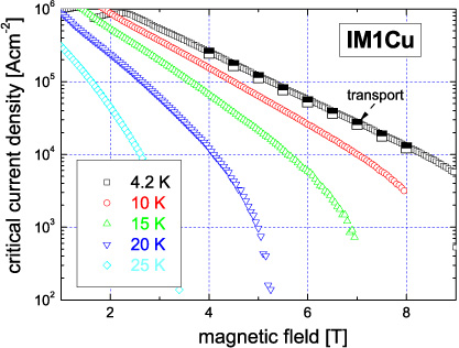
Figure 2. Critical current densities of IM1Cu wire obtained by VSM measurements and by DC transport current.
Download figure:
Standard image High-resolution imageOne can see very good agreement between the Jcm(B) and Jct(B) measured at 4.2 K, which was not observed for the PIT in situ made MgB2. Usually, the in situ MgB2 wire shows different field dependences for Jcm and Jct. A relatively good agreement of Jcm and Jct was obtained at a low field, but as the field increased to around 8 T (at 4.2 K) the Jcm began to drop much faster than the Jct due to the different current paths for the magnetic and transport current measurements [17]. Consequently, different Jcm(B) are measured when the field direction is parallel or perpendicular to the wire axis due to anisotropic structure of the in situ MgB2 wires [18].
The estimation of induced electric field during the magnetization was performed for IM1Cu wire by equationE ≈ (d/2)dB/dt, where d is the outer diameter of MgB2 core and dB/dt is the applied sweep rate (6 mT s−1) [19]. The estimated electric field of 1.8 × 10⁻⁸ V cm−1 correlates well with the E ≈ values calculated for variable dB/dt, ranging from 1 to 18 mT s−1 [19], but it is much lower than the electric field criterion applied for transport measurement (10−6 V cm−1). Taking into account the large n index of IM1Cu wire (∼40 at 6 T), the comparison of transport and magnetization Jc is reasonable. Identical Jcm(B) and Jct(B) dependences measured at 4.2 K for IM1Cu wire (shown in figure 2) demonstrate the isotropic character of MgB2 made by IMD.
Figure 3(a) shows broken IM1Cu wire with clearly visible central hole, MgB2 area and Ti barrier, and figure 3(b) shows a metallographic view with a compact and hard MgB2 layer of average thickness ∼70 μm. Average microhardness of HV 0.05 = 1600 MPa was measured in this layer after HT at 640 °C/1 h, which is considerably higher in comparison to in situ MgB2 with HV 0.05 = 350−500 MPa HT at 650–800 °C/0.5 h [20].
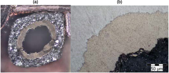
Figure 3. Cross-section of broken single-core IM1Cu wire (a), and metallographic view to MgB2 layer with uniform structure after heat treatment at 640 °C/1 h (b).
Download figure:
Standard image High-resolution imageFigure 4(a) compares the critical current densities at 4.2 K for undoped MgB2 (extrapolated to zero field) obtained by the presented IMD process with PIT: I in situ, E ex situ, M mechanical alloying [21] and also with thin MgB2 film made by molecular beam epitaxy (MBE) [22]. More than one order of magnitude higher Jc are obtained by IMD in comparison to the in situ PIT process. IMD wire IM1Cu subjected to pressing by 1.9 GPa shows an additional Jc increase of 40%, which correlates with the increased core hardness HV0.05 of the MgB2 layer from 1600 to 1750 MPa. This confirms the importance of boron powder density for the final current carrying capacity of the MgB2 compound made by IMD. Also of interest is the identical slope of Jc(B) for I and IM1Cu, which is different in comparison to E, M and MBE. The best Jc(B) dependence is obtained for well textured 200 nm thin MgB2 film made by MBE with larger Jc for the B direction in the c-axis of MgB2 grains (perpendicular to MgB2 film) and a lower one for B perpendicular to the c-axis [22]. Jc extrapolated to low field region (B < 2 T) indicates comparable current densities for E, IM1Cu and MBE approaching 107 A cm−2 at self-field and ∼106 A cm−2 at 2 T. Therefore, these three techniques seem to be promising for the low field application of MgB2. Figure 4(b) compares the engineering current densities (Je) measured for IM1Cu, IM4Inc and IM4Gli wire at 4.2 K. Although the fill factors of these wires are quite low (5.7–9.4%), Je values (104 A cm−2 at 3.5–5 T) are high enough to be interesting for possible medium field generation at 4.2 K. Further optimization of IMD wire composition (e.g. increased MgB2 content) is able to increase Je to higher values.

Figure 4. Comparison of critical current densities of MgB2 obtained by IMD, powder-in-tube (PIT) and by molecular beam epitaxy (a), engineering current densities (Je (4.2 K)) measured for IM1Cu, IM4Inc and IM4Gli wire (b).
Download figure:
Standard image High-resolution imageFigure 5(a) shows the critical currents for IM4Gli wire measured by pulse currents (PCs) between 4.2 and 20 K and external fields of 1–9 T [13]. Comparison of Ic obtained by DC and by PC measurement at 4.2 K and B = 4−8 T (see figure 5(a)) shows good agreement. The corresponding engineering current densities are plotted by figure 5(b):Je = 104 A cm−2 measured at magnetic fields between 2.5 and 5 T for the temperature range of 4.2–20 K makes this conductor suitable for cryogen-free applications and for generating low magnetic fields 0.5–3 T, for example in MRI systems [23] or for large wind power generators [24].

Figure 5. Critical currents of IM4Gli wire measured by pulse currents at temperatures 4.2–20 K and external fields 1–9 T (a) and corresponding engineering current densities Je(B) (b).
Download figure:
Standard image High-resolution image3.2. Critical current anisotropy
Critical currents of IM1Cu tapes with thickness 0.69 and 0.48 mm were measured in the parallel and the perpendicular field direction. Figure 6(a) presents the ratio ka = Ic−par/Ic−perp for these tapes having aspect ratio (width to thickness) b/a = 2 and 3. It is apparent that the current anisotropy of IMD tape increases with the field magnitude and also with b/a ratio.
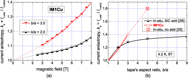
Figure 6. Critical current anisotropy ratio ka = Ic−par/Ic−perp for IM1Cu tapes with the aspect ratio b/a = 2 and 3 (a) and ka (8 T) versus b/a for PIT in situ and IMD tapes (b).
Download figure:
Standard image High-resolution imageThis indicates that some preferential orientation of MgB2 grains was formed during the Mg-diffusion into the boron layer. The texture of rolled Mg particles and consequent Ic-anisotropy affected by the additions into the Mg + B mixture has been already shown for in situ MgB2 tapes [25, 26]. Figure 6(a) shows a similar behaviour for flattened Mg core surrounded by boron powder. The anisotropy of the in situ MgB2 and IMD is compared in figure 6(b), where the ka ratio at 8 T is plotted versus the aspect ratio b/a. In the case of no addition into MgB2, the ka is increasing linearly with b/a for IMD tapes and likewise for in situ tape with b/a = 5 [25], which follows the same tendency. Carbon addition through SiC particles increases the upper critical field of MgB2 apparently [27]. At fixed intrinsic anisotropy  , the current anisotropy ka is a function of the reduced magnetic field b = B/Bc2 [28] and is also affected by the texture induced by rolling deformation. An increase of Bc2 reduces b = B/Bc2 and consequently a decreased ka(B) is measured at the given scale of external field [26]. Figure 6(b) confirms the same mechanism of Ic-anisotropy for the rolled in situ and for IMD MgB2 tapes. This is explained by the preferred orientation of MgB2 caused by axially unsymmetric Mg-diffusion into boron from the flat Mg core and/or flat Mg particles.
3.3. Current degradation by twisting
In relation to possible AC applications, the low loss of MgB2 is an important issue. This could be decreased effectively by a proper twisting of MgB2 filaments reducing the filament's coupling. But the twisting process introduces torsion stress into composite wire and it may reduce the critical current considerably [29]. Therefore, IM4Gli wire of 0.86 mm has been twisted with variable twist pitches Lt = 2.5−50 mm, heat treated and measured at 4.2 K. Figure 7(a) shows the Jc(B) characteristics of twisted wires compared to untwisted wires. The small Jc degradation caused by twisting up to short twist (2.5 mm) is surprising. Consequently, Jc = 104 A cm−2 measured at B = 7.6 T in untwisted wire is shifted only slightly to B = 7 T for Lt = 2.5 mm. Figure 7(b) compares the normalized critical currents versus the Lt/dw ratio (dw is the wire diameter) for two different in situ samples and IM4Gli wire.

Figure 7. Jc(B) characteristics of twisted IM4Gli wires (a), comparison of critical current degradation of IM4Gli wire with two in situ wires (b) and magnetization AC losses versus the temperature for differently twisted wires measured at 72 Hz and external field 37 mT (c).
Download figure:
Standard image High-resolution imageIt has been already shown that critical degradation by twisting depends on the wire composition, filament structure and heat treatment conditions [29]. Reduction of the current carrying capability in twisted in situ wires is attributed to the reduced filament's density prior to final heat treatment [29]. Figure 7(b) shows the corresponding critical current degradation for in situ 4- and 30-filaments wires sheathed by AgMg and GlidCop, respectively. The mechanically stronger GlidCop sheath makes it possible to apply shorter Lt than the softer AgMg one. The IM4Gli wire shows 90% of the original Ic for Lt/dw = 10 (Lt = 8.6 mm). The smaller sensitivity of IMD wire to twisting can be attributed to the lower sensitivity of boron powder density reduced by torsion stress in comparison to the Mg + B powder mixture used for the in situ process. Figure 7(c) presents the measured magnetization AC losses versus temperature for twisted IM4Gli wires at frequency 72 Hz and external field 37 mT. The plateau of losses at temperatures near to 18 K indicates the presence of coupling currents. AC magnetization losses of all samples increase with the temperature from 18 K up to a maximum at 32 K. This is caused by decreased critical current density Jc and subsequent penetration of the magnetic flux deeper into the filaments at the AC field of 37 mT, which results in a hysteresis loss addition to the coupling ones. The maximum of the AC loss represents full penetration of the magnetic flux at given temperature and AC field. One can see that the AC loss due to coupling current is considerably decreased by the applied twisting to Lt = 10 and 5 mm. The AC loss of this wire at 20 K is reduced by ∼60% for Lt = 10 mm (∼90% Ic) and by one order of magnitude in comparison to the untwisted one with Lt = 5 mm (∼80% Ic). Consequently, low critical current reduction by twisting and effective reduction of AC losses can be utilized for future filamentary IMD wires.
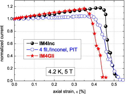
3.4. Tolerance to axial tension
Practical superconducting wires are usually tested by axial tension to unveil their strain tolerance, which is important for possible coil applications. Figure 8 shows normalized Ic(ε) dependences for the two presented IMD wires (IM4Inc and IM4Gli) and for one in situ four-filament wire sheathed by Inconel [30]. A nearly identical increase of critical current with the tensile strain has been measured for both IM4Inc and IM4Gli wires at ε < εirr. The less gradual Ic degradation of the in situ wire above εirr in comparison to IM4Inc and IM4Gli wires can be explained by the different MgB2 cores densities (HV 0.05 ∼ 1600 MPa for IMD, and ∼400 MPa for in situ [20]). A similar difference has been observed between in situ and ex situ MgB2 wires subjected to tensile stress, where better connected grains of the in situ wire showed more radical Ic decrease above εirr.
Figure 8. Normalized Ic(ε) dependences measured for IM4Inc and IM4Gli wires compared with Inconel sheathed four-filament in situ wire [30].
Download figure:
Standard image High-resolution image
Comparably designed in situ wire with Inconel sheath also shows less steep Ic increase below εirr than does IM4Inc. The IM4Inc wire also has higher irreversible strain of 0.43% in comparison to the in situ one of εirr = 0.38%. Nishijima et al have compared the strain tolerance of two MgB2/Fe wires made by in situ PIT and IMD processes [31]. The IMD-processed wire showed larger irreversible strain and smaller strain sensitivity than the PIT-processed one (εirr is 0.67% and 0.54% for IMD and PIT wires, respectively), which has been explained by a porous structure of the MgB2 made by the PIT process. It should be noted that different HTs have been used (670 and 800 °C) for the compared wires [31], which also influences the mechanical strength of the iron sheath. Similarly, in our case HTs at 640 and 850 °C have been applied for IMD and PIT, which affect the strain tolerances of the compared conductors as already shown for filamentary MgB2 wires with variable sheaths and HT conditions [32].
4. Conclusions
Single- and four-core MgB2 wires have been made by the process of internal magnesium diffusion into boron. The identical in-field dependences of current density obtained by magnetic measurement (at which the induced current are circulating across the MgB2 core) and by transport measurement (with only longitudinal current flow) demonstrates the uniform character of the MgB2 layer made by the IMD process. High critical current densities could be reached by this process in low external fields, which is not possible by the in situ PIT process. It was shown that the boron powder density influences the current carrying capacity of MgB2 wires made by IMD. The same mechanism of critical current anisotropy has been found for in situ and IMD tapes, which is explained by the preferred orientation of MgB2 caused by axially unsymmetric Mg-diffusion into boron from the flat Mg core and/or flat Mg particles. The small critical current degradation of IMD wire by twisting can be utilized for effective reduction of AC losses. High engineering current densities are interesting for the generation of magnetic fields of 1–3 T at cryogen-free conditions, which can be utilized in future MRI systems or wind power generators.
Acknowledgments
This work was supported by the Slovak Scientific Agency under projects APVV-0495-10 and VEGA 2/0121/12.