
Abstract
Magneto-rheological (MR) dampers are a promising type of semi-active control device for various dynamic systems. Recently, low-cost MR dampers without any sealing structure have been required. Motivated by the desire to overcome the need for the costly dynamic seals of conventional MR dampers, a new type of metal foam MR damper is proposed in this study and the dynamic response performance is also investigated. The metal foam is firmly adhered to a working cylinder to store the unexcited MR fluids. In the action of a magnetic field, MR fluids will be extracted from the metal foam and fill up the shear gap to produce the MR effect. Three time parameters related to response time are introduced to further describe the dynamic response process. The results show that, due to the period required for extracting the MR fluids out from the metal foam, the time to produce the damper force of the metal foam MR damper is longer than for conventional fluid-filled MR dampers. The response time of the metal foam MR damper will change with different currents and shear rates. Given a constant shear rate, in a small range of currents (0–1.5 A), the response time decreases rapidly as the operating current increases; however, there is a slower change rate in larger ranges. To evaluate the effect of shear rate on response time, shear rates ranging from 2 to 10 s−1 are tested, and the results demonstrate that with increasing shear rates the response time decreases.
Export citation and abstract BibTeX RIS
1. Introduction
Magneto-rheological (MR) fluids, typically composed of high concentration micron-sized carbonyl iron (CI) particles and water or oil, are one kind of smart material that exhibits fast, reversible and tunable transition from a free-flowing state to a semi-solid state of chain-like structures on the application of an external magnetic field for a few milliseconds (Carlson and Sproston 2000).
Over the past few decades, MR fluids have received a lot of attention in research and applications (Klingenberg 2001, Kordonsky 1993), among which MR dampers have been widely used in vibration controls of civil engineering structures, automobile suspension systems, railway vehicles, MR finishing etc (Tse and Chang 2004, Zhou et al 2002, Gordaninejad et al 2010, Lam and Liao 2003, Sung and Choi 2008, Yu et al 2009, 2011, Liao and Wang 2003, Rizzo et al 2007, Stephen 2007). However, the working cylinder of a traditional MR damper must be full of MR fluids, therefore, one key barrier to widespread commercial application of the device is the relatively high cost compared to conventional passive ones. Carlson (Carlson 1999, Carlson and Sproston 2000, Michael and Carlson 2001) specified the major cost factors in MR fluid devices including dynamic seals, surface finishing of moving piston rods, precision mechanical tolerances and the volume of MR fluids. The design of current MR dampers requires a high quality of seals to stop the leakage of MR fluids. Besides, with moving the piston rod, the suspended magnetic particles of MR fluids getting into the sliding contact of the seal will cause serious damage to the surfaces.
As mentioned above, Carlson (Carlson 1999) introduced the idea of using a sponge as an absorbent matrix to contain MR fluids for an MR damper. The sponge wrapping around the piston of the damper avoids MR fluids leaking out of seals and keeps them in position. However, the sponge idea suffers from some major problems: the relatively large thickness of sponge required to ensure a sufficient amount of MR fluids, which would significantly reduce the magnetic field strength; the relatively small amount of MR fluid used repeatedly under excited conditions would cause the drop of the MR effect; the durability of the sponge used under high shearing conditions is also a question. Therefore, Liu (Liu 2010, Liu et al 2010) proposed that a stronger type of porous material, namely, metal foams, should be used to store the MR fluids for the MR actuator. The unexcited MR fluids stored in the metal foam are extracted to fill the gap with the help of the external current. It is also proved that the change of characteristics of MR fluids flowing through is small enough to be ignored (Liu and Jin 2011).
While the previous studies on MR dampers with metal foam have shown some promising results, no MR damper has really been designed with the idea of using metal foam to store and release MR fluids to reduce the cost.
Considering the above mentioned development of MR dampers, it would be beneficial to use metal foam for an MR damper to avoid leakage from sealing in further applications. With this motivation, we aim to design and implement a low-cost MR damper without any sealing. In this paper, a new type of MR damper, called a metal foam MR damper, which can be applied to areas wherever a direct shear mode of operation would be used, is put forward and fast response time is also investigated. They are particularly appropriate for less demanding, low-force applications where a high degree of control is desired. The design of and prototype experiments with the dynamic response performance of the metal foam MR damper will be presented. Three time parameters, τdelay,τref, τresponse, are defined to further investigate the dynamic response characteristics. The possible influencing factors of response time for metal foam MR damper such as excitation currents and shear rates are explored. Finally, in view of MR fluids flowing mechanism in metal foam MR damper, the behavior of the longer response time compared with traditional MR damper is discussed.
2. Metal foam magneto-rheological damper
Figure 1 displays the schematic and a photograph of the metal foam MR damper. The number of turns of the coil is 1635 of 0.5 mm diameter copper wire, 20# steel is used for the working cylinder and the piston rod to obtain high levels of magnetic saturation and low residual magnetization, while the relatively low-magnetic 45# steel is for the cylinder end cap. The porous foam nickel is adhered to the inside of the working cylinder before injecting the MR fluid. The magnetic field route is composed of the cylinder, metal foam, shear gap and piston. To make sure the magnetic field lines go along the expected route, both ends of the cylinder are fixed with a piece of 2 mm bronze. The basic specifications of the electromagnet are shown in table 1. The other dimensions can be obtained by the ratio in table 1.

Figure 1. Metal foam MR damper: (a) schematic of the designed damper; (b) photograph of the designed damper.
Download figure:
Standard imageTable 1. Main parameters of the metal foam damper.
| Maximum stroke (mm) | Number of coils | Turns of coil | Shear gap (mm) | Diameter of cylinder (mm) | Effective length of piston (mm) |
|---|---|---|---|---|---|
| ±60 | 1 | 1635 | 1 | 44 | 90 |
The working principle of a metal foam MR damper can be demonstrated as follows: the MR fluids in the metal foam MR damper are constrained by gravity and capillary action in the metal foam when the magnetic field is off. Most commonly, this metal foam is made from an open-celled metal material with porosity 80% or more. As shown in figure 2, the porous metal foam storing MR fluids is adhered to the inner working cylinder of the damper. Application of the magnetic field causes the MR fluids in the metal foam to be extracted out and then fill up the shear gap to produce the MR effect. The amount of force produced is proportional to the MR fluids' volume moving with the piston. The velocity of the moving piston is a pre-set constant value. In contrast, as soon as the magnetic field is removed, with the help of gravity and the capillary force, some of the MR fluids are recycled by flowing back into the metal foam. The traditional MR damper needs to be filled with 90 ml MR fluids to produce an MR effect, but only 30 ml, one third of the MR fluids, is needed for the proposed metal foam MR damper, and it does not use any sealing structure, which can greatly reduce the cost and have broad applications.

Figure 2. The principle of the metal foam MR damper: (a) a sketch of the inner structure when B is off; (b) a sketch of the inner structure when B is on.
Download figure:
Standard imageAs mentioned above, three processes can be found in this design: firstly, MR fluids are extracted out from the metal foams and then begin to fill the shear gap, then the MR effect is produced. Thus, it is feasible to change the response of the metal foam MR damper by adjusting the current. There are many other differences compared with the usual MR damper as referred to by Liu (Liu 2010), especially with regard to the dynamic response.
2.1. Experimental setup and methods
This section details the experimental materials and setup, describing the system used in this study. The experimental damping force is also given to verify the performance of the test rig.
2.2. Materials
The specimen is MR Fluid-J01T from the Chongqing Instrument Materials Institute, the viscosity at zero magnetic fields is 0.8 Pa s, and the MR particle has typical dimensions of around 1–5 μm in diameter, as shown in figure 3(a). Figure 4 describes its magnetic characteristics and shear stress curve. When the magnetic field density B is 0.5 T, the shear yield stress is about 60 kPa. The porosity of porous foam metal nickel is 110 pores per inch (ppi), the initial permeability is 1.5 and thickness is 2 mm, which is the same as in (Liu 2010) and displayed in figure 3(b). According to Liu et al (Liu and Jin 2011), when MR fluids flow through the metal foam, the clogging in the flowing process can be neglected.

Figure 3. Photographs of experimental materials: (a) particle size distributions of MR fluids; (b) inner structure of the porous metal foam.
Download figure:
Standard image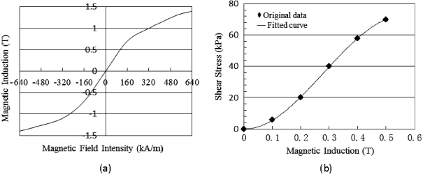
Figure 4. Magnetic characteristics of MR fluid-J01T: (a) B–H curve; (b) shear stress versus magnetic induction curve.
Download figure:
Standard image2.3. Experiment setup
Figure 5 presents a photograph of the entire test system. In addition to the metal foam MR damper, the system also has several other major components. The metal foam MR damper is driven by a DC motor (model: YJ01) whose speed can be adjusted by a controller with a speed encoder. A force sensor with an amplifier is used to measure the damper force delivered through the metal foam MR damper. The coil is activated by the power supply. The test signals are gathered and processed by the DAQ and PC with LabVIEW software. A timer was designed to synchronize the start of the magnetic field application and the measurement starting point. The strength of the magnetic field can be adjusted by changing the current.

Figure 5. Test rig of the metal foam MR damper.
Download figure:
Standard image3. Finding the response time
This section describes the experimental procedure to find the response time for the metal foam MR damper. To clearly explain the transient time, three time parameters are defined, and an example of the testing response time is shown to demonstrate the procedure.
3.1. Response time procedure
In order to interpret clearly the rising and falling response times of the metal foam MR damper, three time parameters are defined, τdelay,τref and τresponse. Here, τdelay is defined as the time period from current on to the damper force signal being detected (during which MR fluids are drawn out from the metal foam to the shear gap); τref is the time for the damper force to acquire 63.2% of the steady damper force . The reason for choosing 63.2% as a reference is given in Koo (Koo et al 2004) and Koo (Koo et al 2006); τresponse, which is the total response time, is defined as total time from current turned on to the first steady state achieved. (The reason for choosing the first steady state is discussed in the following section.)
Figure 6 illustrates the method for measuring the rising and falling response time. There are two channels for the DAQ card and LabVIEW software, that is, two signals will be received and recorded in the PC. One of them is for the damper force signal from the metal foam MR damper, which includes the response time of the force sensor, DAQ and computer. The other one represents the reference signal which is determined by the time when the switch is on and off; the response time of the DAQ and computer are also included in this signal.

Figure 6. Damper force versus time.
Download figure:
Standard imageAs different channels have different response times, each of them is tested before the experiment. The results show that, while providing a constant voltage, the time interval of these two signals is less than 1 ms. As the response time of the metal foam MR damper is in milliseconds, a time delayer with minimal scale in milliseconds is necessary.
For the sake of accurately evaluating the response time of the metal foam MR damper, the effect of operating current on response time is the first parameter to consider. Therefore, four operating currents, ranging from 0.5 to 2 A in increments of 0.5 A, are used, and the effect of shear rate on response time is also investigated, where the constant shear rates are 2 s−1,4 s−1,6 s−1,8 s−1 and 10 s−1, separately. It should be noted that due to the milliseconds response time for the MR damper, a relatively high frequency, 5.12 kHz, is required to precisely obtain the response time.
As can be seen in figure 6, there is not only one steady state during the test. It mostly depends on the working mechanism of the proposed damper as mentioned in section 2. Only the MR fluids reach the piston and move with it, producing the MR effect. The more the MR fluids move with the piston, the greater the damping force.
Therefore, in the following data processing, the defined time parameter, τresponse, is from the current being turned on to the damping force reaching the first steady state value, as mentioned in section 3.1.
3.2. Response time example
A typical experiment, as an example, is completed to explain the meaning of the time parameters. The relationships between damping force and currents are shown in figure 7. Here, the current in the loop is 0.5 A and the shear rate is 6 s−1. As can be seen from figure 7(a), with regard to the rising process, the delay time τdelay is 26 ms, time τref is 189 ms and the time τresponse is 250 ms. Meanwhile as to the falling response time, τresponse shown in figure 7(b) is 237 ms and the time τref is 57 ms. Moreover, in the conditions that the shear rate is 10 s−1, the rising time and falling time parameters as functions of current are also displayed in figure 8.
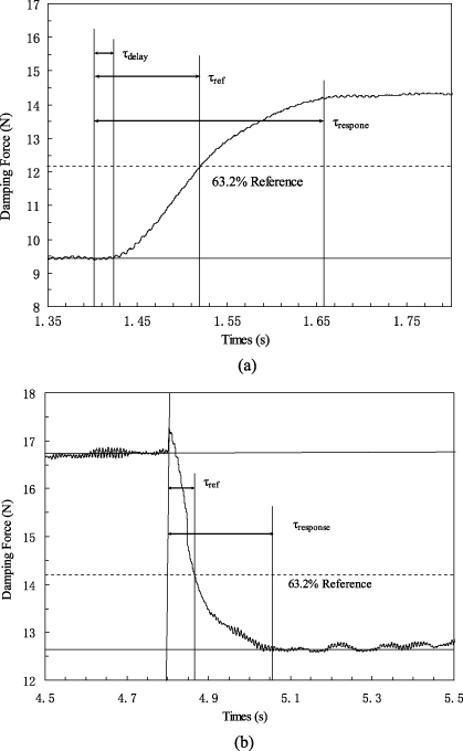
Figure 7. The typical definition of time parameters for the metal foam MR damper: (a) damping force versus rising time; (b) damping force versus falling time.
Download figure:
Standard image
Figure 8. Time parameters versus current at a shear rate of 10 s−1: (a) rising time parameters versus current; (b) falling time parameters versus current.
Download figure:
Standard imageAs can be seen from these figures, the delay time, τdelay, decreases with increasing current. Therefore, the dynamic response time of the metal foam MR damper can be adjusted by the external current.
4. Results and discussion
In the following sections, the response time of the metal foam MR damper will be shown from experimental results. The relationships between the response time and the operating currents and piston shear rates are presented.
4.1. Experimental results of response time for the metal foam MR damper
In order to make clear the relationship between the dynamic response time parameters and currents and shear rates, a set of experiments is carried out. Four different currents, that is, 0.5, 1.0, 1.5 and 2.0 A are employed. Referring to the influence of shear rates on the response time, the response time is tested for several shear rates, 2 s−1,4 s−1,6 s−18 s−1 and 10 s−1, separately. The results are displayed in figure 9 and 10.
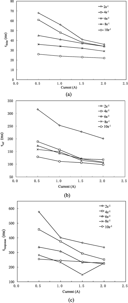
Figure 9. Experimental results of rising time parameters versus current: (a) τdelay; (b) τref; (c) τresponse.
Download figure:
Standard image
Figure 10. Experimental results of falling time parameters versus current: (a) τref; (b) τresponse.
Download figure:
Standard image4.2. Effect of current
Figures 9 and 10 exhibit the dynamic response time for each operating current with different shear rates. The three defined time parameters are discussed in detail as follows.
The delay time, τdelay, decreases with increasing currents. During the period of MR fluids being extracted from the metal foam to fill up the shear gap, the force on the MR fluids mostly depends on the magnetic field intensity, and it will increase with increasing magnetic field strength. According to Newton's second law, the acceleration of MR fluids also becomes larger, so does the velocity. Therefore, when magnetic field strength is increased, the response time will be shorter.
After MR fluids fill up the shear gap, τref, the time that the damper force begins to change until 63.2% of the maximum steady state damper force will also decrease with increasing current, which may be because, with increasing the current, the magnetic field intensity in the gap also becomes bigger, so magnetic particles in the MR fluids move more easily to form a chain and, consequently, the time becomes shorter. Considering the above mentioned, the total rising time, τresponse, also decreases with increasing the current.
However, the rising time includes the time the MR fluids are extracted out from the metal foam while the falling process does not, but the latter is still longer than the total rising response time, which can be seen in figure 11, where the shear rate is 2 s−1, as in the other operation conditions. This may be due to the residual magnetism effect in the metal foam when the magnetic intensity disappears.

Figure 11. Rising time versus falling time at a shear rate of 2 s−1.
Download figure:
Standard imageFurthermore, whether considering the rising or falling time, in a relatively small range of currents from 0.5 to 1.5 A, the response time firstly decreases sharply as the current increases; whereas, with currents beyond 1.5 A, the changing rate of the response time is not so quick and can even remain relatively constant. Compared with the larger current, when currents are small the magnetic particles dispersed in MR fluids are easy to move, therefore, the time spent being a chain is shorter.
4.3. Effect of shear rate
As seen from figure 9 and 10, we can see that whatever the rising or falling time, τdelay,τref and τresponse have the same change trend as increasing currents. That is, the response time will be shorter when the shear rate becomes faster. The faster the shear rate, the easier for the shear yield stress to be reached for MR fluids and, therefore, the shorter the response time for the metal foam MR damper.
However, for τdelay, in a large range shear rate from 6 to 10 s−1, the time does not obviously depend on shear rate.
5. Analysis of dynamic response time for the metal foam MR damper
This section discusses the dynamic response time of the metal foam MR damper in view of the mechanical flow of MR fluids in the metal foam MR damper.
Figure 12 demonstrates the reasons why the response time of the designed metal foam MR damper is much longer than for conventional ones. The three working stages mentioned in section 2 can also be found in these figures.

Figure 12. Analysis of response time for the designed MR damper: (a) no MR fluids in the shear gap, B = 0; (b) MR fluids are drawn out to fill the shear gap, B = B1; (c) the damping force begins to appear, B = B2 > B1.
Download figure:
Standard imageFigure 12(a) shows that when the current is off, the unexcited MR fluids are stored in the metal foam for zero magnetic field strength in the damper; once the current is turned on and there is magnetic induction to achieve B1, in the action of the magnetic force, MR fluids in the metal foam begin to be extracted out and fill up the shear gap, taking time τdelay, as explained in figure 12(b); figure 12(c) demonstrates that the response time, τref, notifies the change of damping force as soon as the magnetic induction comes to B2 and then finally to a steady state. It should be noticed that the magnetic induction B1 is smaller than B2 and the response times τdelay and τref are all included in the total rising response time τresponse.
Therefore, due to the period during which MR fluids are extracted from the metal foam of the metal foam MR damper, the dynamic response time from current being turned on to the damping force signal being detected and finally reaching a steady value is a little bigger than the conventional MR damper previously reported (Koo et al 2006, Kavlicoglu et al 2007, Sahin et al 2012).
6. Conclusions
A new type of metal foam MR damper is introduced and its dynamic response performance is investigated. Three time parameters are defined to demonstrate the dynamic response in detail; various operating currents and shear rates influencing the response time of metal foam MR dampers are particularly observed. The results indicate that, due to the period in which MR fluids are drawn out from the metal foam, the response time of the metal foam MR damper to produce the MR effect is longer than in conventional dampers. Furthermore, we also account for reasons for the longer response time in view of the MR fluids' flow mechanism in the metal foam MR damper.
The experimental results also show that the volumes of MR fluids needed in the metal foam MR damper are much less than in traditional ones, which greatly reduces the cost of MR dampers. Nevertheless, compared with the sponge MR damper reported by Carlson, the metal foam MR damper has the advantages of durability, longer life and better permeability, which may provide a new method for designing low-cost MR dampers.
Acknowledgment
This research is fully supported by the National Natural Science Foundation of China under grant number 51105256.