
Abstract
With the potential of commercially viable global wind power, the use of wind energy is expected to rise further, along with related problems. One issue is collision of the wind turbine blades with the tower during operation. Structural health monitoring is required to improve operational safety, minimize the risk of sudden failure or total breakdown, ensure reliable power generation, and reduce wind turbine life cycle costs. To this end, large numbers of sensors such as fiber Bragg grating and piezoelectric devices have been attached to the structure, which is uneconomical and impractical for large wind turbines. This study proposes a single laser displacement sensor (LDS) system in which all of the rotating blades can be cost-effectively evaluated. In contrast to the approach of blade sensor installation, the LDS system is installed in the tower to enable noncontact blade displacement monitoring. The concept of a noncontact sensor and actuator and their energy delivery device installed in the tower will enable various approaches for wind turbine structural health monitoring. Blade bolt loosening can cause deflection in an affected blade. Similarly, nacelle tilt or mass loss damage in a blade can result in changes in blade deflection, but the proposed system can detect such problems early on.
Export citation and abstract BibTeX RIS
1. Introduction
Renewable energy is considered to be a good alternative for handling issues related to fossil fuel and environmental pollution. Wind energy, as one such renewable energy alternative, has shown substantial growth. Some countries extensively support wind power and are trying to develop it as their major source of energy [1]. A positive trend can be seen, with 37.5 GW of wind power capacity having been installed worldwide in 2009, bringing the total cumulative capacity to 157.9 GW. Despite widespread financial crisis and economic recession, the wind power industry is growing rapidly.
However, operational accidents had also increased by a factor of 3.6 by 2010 compared to the year 2000 [2]. Blade rotor structures are composed of various components and subsystems that are susceptible to structural damage as well as bearing, spindle, or gearbox failure. Accidents are a threat to the wind turbine system itself and a public safety concern. According to the Caithness Windfarms Information Forum [2], the data from 1975 to 2011 for the world's major wind turbine farms show catastrophic wind turbine failures, including blade failure, fire, non-blade-related structural failure, and ice throw, accounting for 41.3%, 30.8%, 22.1%, and 5.8% of the total failures, respectively.
The facts show that approximately 63.4% of the structural damage in wind turbines leading to accidents has indicated some sudden deformity or displacement changes between the blade and the tower early in the turbine's life. Taking this into consideration, any such behavior in the wind turbine system could be considered a symptom of failure. Relative displacement monitoring of the blades in the tower could thus prevent catastrophic accidents like collision of the wind blades with the tower if such flaws could be detected in advance to allow for the implementation of necessary preventive measures. Also, since wind turbines generally have multiple blades, relative comparison of the distances between the blades and the tower is also an important diagnostic element that could help to prevent failures due to collision accidents.
In this note, a few possible failure events have been considered that could cause variation in the distance between the blades and the tower and lead to blade deflection and collision. Bolts of different shapes and sizes are used to fasten various structures. Bolt loosening is one of the causes of blade deflection [3]. Abnormal tilt of the nacelle and the rotor shaft can also cause all of the blades to deflect, causing collision as the blades come close to the tower due to the nacelle tilt [4]. Wind turbines with curved blades (e.g. Vestas, V112) can increase blade stiffness, which can be realized by composite manufacturing technologies [5]. In this case, the blade tip is closer to the tower than the tip of a straight blade, which also increases the risk of collision accident between the blades and the tower. The tip of the blade is sometimes damaged by lightning [6], which causes a mass difference among the blades that leads to a rotational imbalance [7], and is considered in this study as a leading cause of collision accidents. A wind power blade deflection monitoring system is proposed that consists of a cost effective, noncontact laser displacement sensor (LDS) that can be installed within the tower and provide real-time health monitoring of the wind turbine blades.
2. A blade deflection monitoring system using a laser displacement sensor
Structural health monitoring of wind turbines has received much attention for more than a decade [8]. Laser Doppler vibrometers (LDV) have been used to determine any faults in blades. However, LDVs have low signal-to-noise ratios. Also, the use of scanning or multiple LDVs [9–11] to cover a large area of the entire blade is practically impossible on an operating wind turbine, and an LDV is 30–200 times expensive than an LDS, depending on its measurable frequency band and scanning capability. In many recent studies, large numbers of fiber Bragg grating and piezoelectric sensors [12–15] have been attached to the structure, which is uneconomical and impractical for large wind farms. Wireless or wired data acquisition (DAQ) for the sensors embedded in a blade to the nacelle and tower has not yet been solved technically and the sensing system is often unreasonable because its price approaches the cost of the blade. Photogrammetry-based displacement monitoring during the operation is also an important approach [16, 17]. However, retro-reflective markers of a few hundred millimeters in diameter must be installed on the blades' outer surfaces, and proper illumination of the rotation blades is needed. Measurement using CCD cameras is only possible at night for sufficient contrast to be achieved, and they are inappropriate for offshore wind turbines.
On the other hand, the LDS system proposed in this note is very cost effective and practical compared to the LDV system, the sensor systems for blade-embedded sensors and photogrammetry. It could be easily installed in towers, and would enable easy measurement of blade displacement from the tower as a continuous condition monitoring system. To detect the deflection of wind turbine blades earlier, an economical LDS (OMRON, 3Z4M) is used, which is composed of a sensor head and a controller. The LDS head employs triangulation measurement principles, whereby the laser emitter projects an infrared laser beam that creates a spot on the rotating blade surface (figure 1). Reflected light from the surface is detected by the light receiver inside the sensor head, at a position in which no special surface preparation is needed for the reflected light because the light receiver detects some of the scattered light from the surface. The displacement values of the blades are acquired through use of a DAQ system (NI, Terminal block 2120 and Digitizer PCI 6221).

Figure 1. The laser displacement monitoring system (LDSH, laser displacement sensor head; ADC, analog to digital converter; DAQ, data acquisition).
Download figure:
Standard imageIn an actual operating scenario within a wind turbine system, the displacement is continuously monitored by impinging the laser beam of the noncontact LDS on the rotating blades in front of the tower. Supplemental material related to this article can be found online (at stacks.iop.org/SMS/22/027002/mmedia). Damage such as bolt loosening, nacelle tilt, or blade mass loss causes measurement irregularities or changes, allowing for the detection of such damage. This allows for preventive measures or repair action to be taken, which prevents serious accidents from occurring. The absence of such a system presents a public safety concern and the possibility of huge economic losses.
The proposed wind turbine blade deflection monitoring system could be installed within the wind turbine tower as shown in figures 2(a)–(c). In this configuration, the laser is directed from the LDS onto the rotating blade to acquire the displacement data. The blades are monitored during rotation, and any displacement relative to the reference data indicates blade deflection. The LDS used in this note can measure a maximum of 60 mm of displacement from the center distance of the measurement range, and has a maximum sampling frequency of 1 kHz. The laser beam size is 1.0 mm × 2.0 mm, and it provides 50 μm resolution. The displacement sensor uses a semiconductor laser as the light source, which has a wavelength of 780 nm and provides 5 mW of output power. The LDS head is 40 mm × 43 mm × 20 mm and requires a hole to be made in the tower wall for installation.

Figure 2. (a) Installation of the blade deflection monitoring system within a tower. (b) Inside an actual wind turbine tower. (c) Inside a wind turbine tower with the laser displacement sensor (LDS) installation.
Download figure:
Standard imageA long-range-capable LDS needs to be used in a large wind turbine system, such as those with more than 1 MW capacity, since the distance between the blade and the tower is also larger. The LDS resolution is comparatively lower in such cases. However, in the case of a large blade, the blade deflection is also comparatively larger; hence, suitable measurement is provided. For example, in the Vestas blade (2 MW V-80), the distance between the blade and the tower is 5.3 m when the blade passes in front of the tower. In such a case, an appropriate commercial LDS (SICK Sensor Intelligence, DT50) provides a 200–10 000 mm range of measurement, 1 mm resolution, and 40 mm maximum displacement.
The analog displacement signal measured by the LDS is calibrated to a digital signal through a DAQ board and the blade deflections are then monitored in real time compared with reference signals in a LabVIEW-platform-based PC. To reduce labor and cable costs, especially in large offshore wind turbines [18], wireless communication can be used between the DAQ module and the PC. For example, a boat with a PC can work as a mobile host checking the health of a wind farm. For this, the wireless communication module should cover a range of 40–50 m (figure 3).
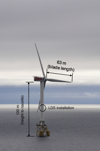
Figure 3. A large wind turbine installed at the Beatrice Wind Farm in Scottish waters (5 MW) [18] and the instrumentation concept of the proposed technique (photograph: Jan Oelker/Repower Systems SE).
Download figure:
Standard image3. Experimental proof-of-concept
3.1. Blade deflection due to bolt loosening
The wind turbine system consists of rotating blades and a power generation system for conversion of kinetic energy from wind into electrical energy. An experimental setup for a typical wind turbine system was designed for this experimental proof-of-concept (figure 4) that consisted of 1.05 m-long wind turbine blades with a rotating motor and a motor controller system. Also, some of the reference data were considered in the selection of a suitable rotation velocity. Data from a real 50 m-long wind turbine blade (2 MW KM43) revealed 70 m s−1 blade tip velocity and 20–30 rpm rotation velocity, and cycles of 2–3 s depending on the wind velocity [19]. Thus, 20 rpm was considered for the rotation velocity.
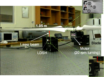
Figure 4. The experimental setup of the blade deflection monitoring system and the bolt-loosening damage.
Download figure:
Standard imageBolts were loosened using a wrench on one of the blades (blade 1), while the other two blades were kept intact. The laser impinges at a point 100 mm away from the tips of the rotating blades at 20 rpm when the blades pass over the LDS. Bolt loosening resulted in deflection of the corresponding blade, which was monitored and verified experimentally. The reference displacement and damaged blade displacement data were acquired before the bolt loosening for comparison to the present state. The reference data acquired before and after bolt loosening for all three blades are shown in figure 5(a). An enlarged view of blade 1 (figure 5(b)) shows a curved distribution due to the blade's airfoil shape. At the maximum camber of the blade, the incident laser beam was diffused and did not sufficiently reach the receiving end, which led to fault measurements at a few sampling points (figure 5(b)). Thus, the average of the leading edge (first measured value) displacement measurement and the trailing edge (last measured value) displacement measurement was used as the representative value for blade displacement upon comparison of the reference and current displacements.

Figure 5. Bolt-loosening monitoring at 100 mm from the blade tip: (a) blade displacement before and after bolt loosening and (b) the measured blade shape in displacement and comparison before and after nacelle tilt in the case of blade 1.
Download figure:
Standard imageTwo bolts in blade 1 (figure 4) were loosened by half and quarter rotations, respectively. Data were acquired by impinging the laser 100–500 mm away from the blade tip at 100 mm intervals. At 100 mm away from the blade tip, the averaged results of comparing the reference and bolt-loosening data showed a deflection of 4.16 mm closer to the tower. Since the data were obtained from various points 100–500 mm away from the blade tip, they were analyzed and compared as deflections versus the point of measurement distance from the blade tip (figure 6). Greater deflection was detected at the measurement point nearer the blade tip compared to points farther away, indicating decreased deflection close to the blade root. The degree of blade loosening could be clearly distinguished in the form of variation of the blade deflection, as shown in figure 6, in which the blades were loosened by half and quarter rotations.
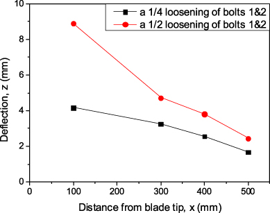
Figure 6. Variation in the amount of deflection upon half and quarter rotation loosening of the bolt and at different distances from the blade tip.
Download figure:
Standard image3.2. Blade deflection due to nacelle tilting
A nacelle is a housing that contains all of the generating components in a wind turbine, including the generator, gearbox, drive train, and brake assembly. As mentioned earlier, nacelle tilt also causes deflection in the blades, and any such abnormal tilt could result in a collision accident. In this experiment, the nacelle tilt effect was simulated by deflection of the motor support by 0.5 mm, as shown in figure 7(b), which created a 3 mm displacement of the nacelle, as compared in figures 7(a) and (b). The resulting blade displacements are plotted and compared in figure 8(a), which was taken from a measurement point 100 mm away from the blade tips. In contrast to the bolt-loosening effect that creates deflection only in the affected blade (figure 5(a)), nacelle tilting results in deflection of all the blades (figure 8(a)). The result was further analyzed and the resultant displacement comparison before and after the nacelle tilt in one of the blades (blade 1) is presented in figure 8(b). It shows that the 3 mm displacement caused by the tilt simulated in figure 7 resulted in a blade deflection of 45.5 mm towards the tower. As obtained from the result shown in figure 5, the deflection is greater at points nearer the blade tip and smaller near the blade root end (figure 9). From this experimental result, it could be concluded that such a phenomenon in which deflection occurs in all the blades simultaneously is the result of problems in the nacelle rather than just the individual blades.
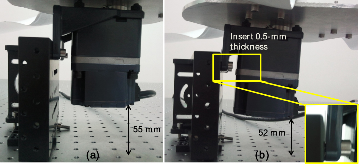
Figure 7. The experimental setup for nacelle tilt: (a) before nacelle tilting and (b) after nacelle tilting.
Download figure:
Standard image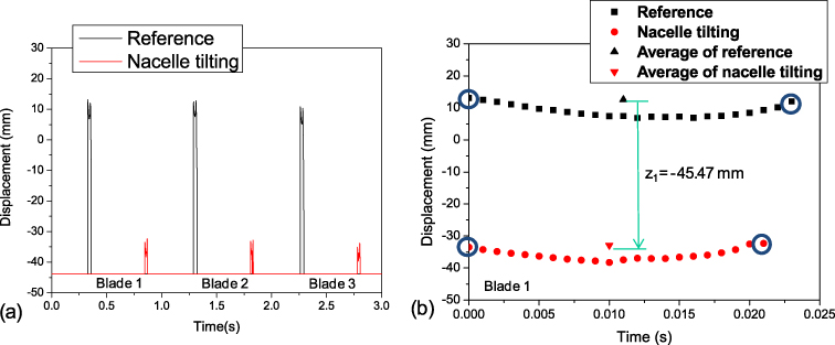
Figure 8. Nacelle tilt monitoring at 100 mm from the blade tip: (a) comparison of blade displacement before and after nacelle tilt and (b) variation in the displacement of blade 1 due to nacelle tilting.
Download figure:
Standard image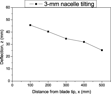
Figure 9. Comparison of the variation in deflection due to the nacelle tilt at different distances from the blade tip.
Download figure:
Standard image3.3. Blade deflection due to a mass loss-damaged blade
One of the problems discussed earlier is blade damage by lightning, which causes a difference in mass among the blades that leads to rotational imbalance. To simulate the mass loss effect, 30 g was removed from the upper surfaces of the blades (figures 10(a) and (b)). This experiment was conducted by considering points of measurement 200–500 mm away from the blade tip to exclude the 150 mm region with mass loss. The variation in displacement as a result of mass loss as compared in all three blades is shown in figure 11(a), showing measurements 200 mm away from the blade tip. The pattern of variation in blade displacement due to the mass loss effect differs from those due to bolt loosening and nacelle tilt. Figure 11(b) shows the displacement variation comparison of blade 1 before and after a 30 g mass loss. The averaged results show that the 30 g mass loss caused deflections of z1 = 3.63 mm, z2 =− 1.52 mm, and z3 =− 2.03 mm in blades 1, 2, and 3, respectively. The deflections at different mass losses with respect to the distance away from the blade tip or near to the root are compared in figure 12.

Figure 10. Blade 1: (a) cutting lines to simulate the mass loss in the surface opposite to the measurement surface and (b) after 30 g mass loss.
Download figure:
Standard image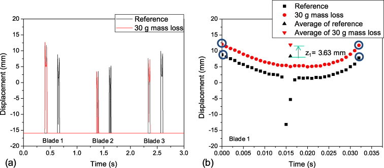
Figure 11. Displacement monitoring of the mass loss by blade tip damage at 200 mm from the blade tip: (a) comparison of blade displacement variation in different blades before and after 30 g mass loss; (b) 30 g mass loss in blade 1 resulted in −3.63 mm blade displacement.
Download figure:
Standard image
Figure 12. Deflection distribution monitoring result at different mass loss amounts and distances from the blade tip.
Download figure:
Standard image4. The effect of temperature on monitoring
The LDS technique has been well established over the last few years, and commercial sensors have sufficient life and environmental resistibility [20, 21]. An experiment was conducted to test the effect of temperature variation using a diurnal range. The experimental setup was the same as in the bolt-loosening experiment. As shown in figure 13, temperature variation itself had a negligible effect on the measurement repeated at three different ambient temperatures. Various commercial sensors are available with different operating temperature ranges. The LDS suitable for the small wind turbine specimen (OMRON, 3Z4M-J1222) has a range of 0–50 °C. Similarly, the LDS considered for a large wind turbine (SICK Intelligence, DT50) has an operational temperature range of −30 to 65 °C. Since the LDS has a lifetime of hundreds of thousands of hours, it requires replacement only once or twice over a turbine's 20-year operating lifetime.

Figure 13. (a) Laser displacement sensor response at various temperatures, (b) displacement comparison at different temperatures.
Download figure:
Standard image5. Conclusion
Wind turbine blades, which are generally made of glass fiber or carbon fiber composites, are very thick and massive structures. Many recent studies of structural health monitoring of wind turbines have relied on numerous built-in sensors and energy-harvesting elements attached to or embedded in the blades; this method is both uneconomical and impractical to cover blades of several tens of meters in practical use. This study proposed a single LDS system composed of an LDS head, a controller, DAQ, and a signal processing module that could effectively monitor the deflections of all rotating blades. The system is cost effective, as it costs only one thousand dollars. In contrast to approaches of sensor installation within the blades, the LDS system is installed in the tower and is used to monitor for any variation in blade displacement. The concept of noncontact sensors/actuators and their energy delivery device installed within the tower will make various approaches for wind turbine structural health monitoring possible.
An experimental proof-of-concept was conducted to test bolt loosening, nacelle tilt, and mass loss due to blade damage. Such failures caused variation in the blade deflection, and the proposed system was successfully and easily able to monitor these changes, as shown in the experimental results. The early detection of failure will be beneficial for inspection decision making and condition-based maintenance. However, since the detection of anomalous blade deflection was not straightforwardly able to ascertain the cause of failure, damage feature extraction and discrimination technologies should be further developed through high frequency, multi-point sensing, and so on.
The proposed system was negligibly affected by temperature variations, making it suitable for implementation in real-life scenarios. The cost effective, compact, and easy-to-install nature of the system also makes it more attractive for field implementation.
Acknowledgments
This study was supported by the Leading Foreign Research Institute Recruitment Program (2011-0030065) through the National Research Foundation of Korea funded by the Ministry of Education, Science and Technology and by a New & Renewable Energy grant from the Korea Institute of Energy Technology Evaluation and Planning funded by the Ministry of Knowledge Economy (20103020020010).