

Abstract
In this study we present an improved approach for the development of auxetics based on the use of deep reactive ion etching (DRIE) after a high-precision mask fabrication procedure. The whole process stands out for its precision (reaching nanometric detail), for the high aspect ratio (AR) attainable and for the possibility of promoting mass production. The quality of the proposed strategy is verified by the manufacture of an auxetic cantilever and bridged structures using two common planar auxetic geometries. The present process significantly increases the precision and AR of the micro-auxetics obtained when compared to state-of-the-art micromachining procedures and solves common challenges linked to structure adhesion to the substrate. The potential of the manufactured structures for the development of resonant structures is analyzed by means of finite-element-method- (FEM) based simulations, showing resonances in the megahertz range. A final application example, linked to monitoring cell culture processes upon auxetic scaffolds, is also proposed and analyzed by computational procedures. The initial cell culture results are also included and help to validate the scaffolds obtained and the materials used for future tissue engineering studies.
Export citation and abstract BibTeX RIS
1. Introduction
Auxetic materials and structures (or auxetic metamaterials) are those with a negative Poisson ratio and that display the unexpected property of lateral expansion when stretched, as well as an equal and opposing densification when compressed (Lakes 1987, Evans 1991, He 2005, Liu 2010). Natural materials (some minerals, skins, etc) and synthetic ones (foams, Gore-Tex®, etc) showing auxetic properties have been described, and very special attention has been paid since their discovery to the search and development of auxetic structures designed and controlled on a molecular scale (Wojciechowski 1987, Evans 1991, Griffin 2005). It is important to clarify that auxetics, which are understood as materials with a negative Poisson ratio, are not only a consequence of special geometries but also of interactions with external conditions and constraints such as negative pressure, proximity of certain phase transitions, specially woven materials, living tissue and their surroundings and polydispersions, among other possibilities described in the seminal papers of this field (Wojciechowski 1989, Hirotsu 1991, Wojciechowski 2003, Narojczyk 2010).
In any case, auxetic metamaterials are being progressively employed in the development of new engineering products, especially in the fields of smart expandable actuators, shape morphing structures and minimally invasive surgical or implantable devices. Regarding smart actuators based on auxetic metamaterials, it is important to mention recent progress linked to auxetic shape-memory alloys (SMA) for developing deployable satellite antennas (Scarpa 2010) and to research on the characterization of polyurethane foams with shape-memory behaviour and auxetic properties, promoted thanks to several post-processing stages (Bianchi et al 2010). In the area of biodevices, recent research has also assessed the behaviour of auxetic structures for implementing expandable stents (Tan 2011, Gatt 2014, Mizzi 2014), and their application to other implantable, surgical or even diagnostic biodevices is clearly a matter of research.
Several auxetic materials and potentially auxetic structures, normally grouped under the terms 're-entrant' (Almgren 1985), 'chiral' (Prall 1997) and 'rotating' (Grima et al 2000) in relation to the characteristics that promote the auxetic behavior, have been summarized in previous reviews and research. However, precise information regarding the values of Poisson's ratios is not always provided due to difficulties with modeling and manufacturing such complex geometries. Sometimes just a scheme of their folding process, when submitted to uniaxial stresses, is provided, which proves to be limited for precise design activities. Recent comparative studies have tried to provide additional information of relevant properties of different auxetic structures in order to assist with material/structure selection tasks for the development of auxetic-based devices (Álvarez Elipe and Diaz Lantada 2012).
Regarding the manufacture of auxetics, to our knowledge, the first successful attempt to obtain such auxetic structures in the microscale for achieving real metamaterials with a negative Poisson's ratio was made by soft lithography, leading to details and pores in the 100 micron range (Xu 1999). However, for adequately exploiting the potential of auxetic metamaterials, an additional degree of precision is needed. For instance, the manufacture of polymeric sheets with an auxetic nanostructure, the pore size of which can be real-time controlled just by applying uniaxial loads, can prove to be useful indeed for developing active selective membranes. Applications in the biomedical field (i.e. dialysis) and in energy (i.e. membranes for catalytic reactors) are worthy of exploration. By rolling such auxetic sheets even easily implantable devices (i.e. stents and anastomosis devices) for minimally invasive surgery procedures can be obtained (Xu 1999).
Tissue engineering with interactions at a cellular and even molecular level can also benefit from auxetic structures (Soman 2012), especially if these preliminary approaches are improved with micro- or nano-auxetics for obtaining increasingly smaller clearances between the cells being cultured. During a cell culture, uniaxial excitations of an auxetic scaffold lead to biaxial expansions and compressions of the tissue being grown, which promotes growth and can potentially control cell differentiation and tissue viability. However, using conventional photolithography or stereolithography for the manufacture of 2D auxetics with typical distances between the lattices of the auxetic structure of around 50 to 100 microns leaves important clearances between cells and prevents them from interacting at the single cellular level.
Not just mechanical applications that benefit from the special properties of auxetic metamaterials take advantage of the micromanufacture; also auxetic devices for optoelectronics and telecommunications require greater degrees of precision than those attainable by traditional micromachining. Some additional remarkable proposals for obtaining real mechanical metamaterials with the finest details reaching hundreds of microns include both subtractive approaches, such as UV laser ablation (Alderson 1999) and additive manufacturing procedures, such as stereolithography, digital light processing or direct laser writing (DLW) based on single- or multi-photon polymerization for enhanced precision (Kadic 2012, Bückmann et al 2012). Normally, 2D and 2D ½ auxetic structures are obtained by means of surface micromachining, chemical etching, laser ablation and typical mass-production processes imported from electronics and, in our case, by improved DRIE. More complex 3D auxetics with intricate geometries and inner details require three-dimensional additive manufacturing or 'layer-by-layer' processes, especially those support-less ones such as selective laser sintering or selective laser melting.
Seminal papers in the field of auxetic metamaterials, linked to the assessment of their vibratory response and resonant properties, have opened new paths toward the application of these geometries for the development of smart sensors and actuators. For instance, the modal analysis of auxetic butterfly cellular configurations has already been studied in depth (Scarpa and Tomlinson 2000), and applications have been also proposed in the aeronautic field (Lira et al 2011). More recently, the vibration of structures with chiral lattices has been reported and applied to impact damage detection using vibro-acoustic modulations (Klepka et al 2013). Novel and very comprehensive monographs on auxetic materials and structures have also paid attention to the vibratory behavior of auxetic rectangular plates that are similar to some of the designs used in our research (Lim 2015).
In this study we present an improved approach for the development of auxetics based on the use of DRIE after a high-precision mask fabrication procedure, which constitutes a relevant improvement of previous promising attempts (Muslija and Lantada 2014). The whole process stands out for its precision (reaching nanometric detail), for the high ARs attainable and for the possibility of promoting mass production. The quality of the proposed strategy is verified by the manufacture of an auxetic cantilever and of bridged structures using two common planar auxetic geometries, one re-entrant and one chiral. The initial static cell culture results are also included and help to validate the scaffolds obtained and the materials used for future tissue engineering related studies.
To our knowledge, the present process significantly increases both the precision and AR of the micro-auxetics obtained (almost by one order of magnitude) when compared to state-of-the-art micromachining procedures and solves common challenges linked to structure adhesion to the substrate layer. The potential of the manufactured structures for the development of resonant structures, which may be applied in high-precision sensors and actuators, is analyzed by means of FEM-based simulations, showing resonances in the megahertz range. A final application example linked to monitoring cell culture processes upon auxetic scaffolds is also proposed and analyzed by similar computational procedures. The cell culture results provide interesting guidance for further research using the obtained auxetic structures. The proposed application may be the basis toward self-sensing micro-/nano-auxetic tissue engineering scaffolds.
2. Materials and methods
2.1. Design process
Two-dimensional auxetic structures are usually based on re-entrant or chiral designs. In re-entrant designs the auxetic behavior is a consequence of a folding/defolding process, while in the chiral designs it is the outcome of rotation, leading to contractions/expansions. By means of example we have chosen a simple re-entrant geometry (firstly introduced by Almgren 1985) and a chiral geometry, both previously included in our systematic library of auxetic geometries (Álvarez Elipe and Díaz Lantada 2012).
The computer-aided design is accomplished using NX-8.5 (Siemens PLM Solutions), firstly by obtaining the unit cells and subsequently by using Boolean operations and two-dimensional matrix replications. The planar auxetics are designed in the XY plane for subsequent extrusion along the z-direction; so, the expected auxetic behavior should lead to transversal contractions along the y-axis when compressed along the x-direction, as well as expansions along the y-axis when tractions are applied along the x-direction.
The process presented in this study may be suitable for the manufacture of several types of planar auxetics, many of which are collected in our recently developed library, but we have selected the geometries shown in figure 1 due to their simplicity, well-understood behavior and versatility. It is important to note that their Poisson ratios can be tuned just by changing the relationships between length, width and unit cell angles (Lira et al 2009, Sun and Pugno 2013) and that they can be manufactured using both subtractive (typically 2D ½ micromachining) and additive approaches. In addition, such geometries can be used as a basis for 3D auxetic structures, either by rolling, stacking or using the same principle but with 3D unit cells, and they can be used for the final development of both planar and three-dimensional auxetic-based devices (Yang et al 2011).
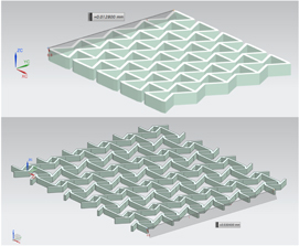
Figure 1. Two-dimensional auxetic structures selected for the present study: Re-entrant structure (upper geometry) and chiral structure (lower geometry). Taken from the CAD auxetic library, developed by Álvarez Elipe and Díaz Lantada (Prall 1997). Upper geometry inspired by Almgren (Klepka et al 2013).
Download figure:
Standard image High-resolution imageAs can be seen in figure 1, the re-entrant design is 12 × 12 × 1 μm3, and the chiral design is 30 × 30 × 1 μm3, with unit cells of 3 × 2.4 × 1 μm3 and 6 × 4.2 × 1 μm3, respectively. The smallest features (truss thicknesses) are around 450 nm. The dimensions are aimed at obtaining unit cells well below the size of most eukaryotic cells for enabling special biomedical applications and at bridging the gap between state-of-the-art micromachined auxetics (with features down to a few micrometers) and molecular auxetics (with features in the tens of nanometers range).
2.2. Manufacturing process
The manufacturing process for obtaining the prototypes of auxetic cantilevers and bridges with nanometric features is accomplished by means of DRIE. The DRIE process used here is based on previous research (Muslija and Lantada 2014), with some important modifications detailed further on. In short, plasma phase etching involves the generation of chemically reactive species accelerated under the effect of an electromagnetic field toward a target substrate, with protected and unprotected zones, thanks to a physical mask. The reactive species are formed by the collision of molecules in a reactant gas with a cloud of energetic electrons excited by a RF field. When the etching is purely chemical, the process is referred to as 'plasma etching'. When the ion bombardment of the silicon surface plays a relevant role, the process is called reactive ion etching (RIE). DRIE evolved from RIE to satisfy the need for an etch process capable of anisotropically etching high AR structures at mass-production rates. The process is similar to RIE, but the silicon substrate is typically cooled to a cryogenic temperature (−80 °C to −150 °C) for promoting condensation of reactant gases (SiOxFy), which protects walls from further etching and re-depositions, helping to obtain high ARs with vertical and smooth walls.
Using cryo-DRIE for silicon, the desired micro-auxetic structures with nanometric details are fabricated. A silicon on insulator (SOI) substrate with a silicon device thickness of 1.0 μm and a 4.0 μm thick box layer is used as support for the process. Due to the very small lateral dimensions of the auxetic structures (minimal bar width ∼300 nm), the layout is written by electron beam lithography (EBL) into a 200 nm thin negative resist (maN). Using a negative resist in this case has some relevant advantages: the EBL writing time is shortened significantly, as only the structure layout itself has to be written and not the whole surrounding area, as would be the case using a common positive resist (e.g. PMMA). Another benefit is the very good selectivity between maN and silicon, thus enabling the application of a considerably thinner resist layer (in comparison to more common PMMA), with the opportunity of writing especially sharp resist structures with high resolution via EBL. After EBL processing and development of the resist, the structures are etched into the device layer using the described cryo-process. Finally, the etched silicon structures are under-etched, removing the oxide layer with HF (wet etching) and thus generating freestanding bridges and cantilevers.
2.3. FEM-based simulations
The different geometries are simulated using the FEM capabilities of NX-8.5 (Siemens PLM Solutions) for studying the vibrating properties of the different auxetic geometries designed and manufactured for analyzing potential applications.
2.3.1. Material and mesh
Triangular 3-node planar elements with an element size of 0.2 μm and a thickness of 1 μm are used for meshing, which is carried out with help of the automatic meshing and refine tool from the software employed. Mechanical properties of conventional silicon have been used as bulk properties, including a Young modulus of 170 MPa, a density of 2330 kg m−3 and a Poisson ratio of 0.25, considering the material isotropic. Similar mesh and material properties have been applied to the re-entrant and chiral structures under study. For modeling the proposal of the application involving a eukaryotic cell attached to the bridged re-entrant structure (preliminarily modeled as a 5 μm diameter μm heigth ellipsoid), the cell has been meshed with tetrahedral 10-node elements with an element size of 0.5 μm. An isotropic material with a density of 1 g cm−3 and a very soft Young modulus of 40 MPa has been applied to the cell for a preliminary simplified structure and due to the computational limitations of the available resources and software used. Using a more precise model with an outer rigid membrane and an inner liquid environment would mean linking several domains and using a more complex solver that is beyond our current capabilities. In addition, the presence of liquids would mean the appearance of several vibration modes at very low frequencies, thus preventing us from obtaining the impact of a cell mass on the auxetic resonances. We have considered the typical extended spheroid form of cells growing upon planar scaffolds and considered them stiffer when extended upon a surface than in their spherical rest state, as usually perceived in planar cell culture processes. The value of Young's modulus is in the range of previous data linked to atomic force microscopy testing upon the stiffest parts of the cytoskeleton such as microtubules and intermediate filaments (Dufrene 2011). Additional details are included in the discussion section.
2.3.2. Boundary conditions
Fixed boundary conditions have been applied to one edge of the structures or to opposite edges so as to adequately resemble the cantilever and bridged auxetic structures, respectively. When dealing with the final application, a contact boundary condition has been applied to fix the cell surface to the auxetic structure in the contact zones.
2.3.3. Solver parameters and post-processing
From the different possibilities of NX-8.5 for carrying out FEM simulations, NX-Nastran solver and structural analysis type (solution type 103-Real eigenvalues). The solver proceeds by linear elimination using the Laczos method for calculating the eigenvalues, linked to mode shapes. Simulations are carried out at a default ambient temperature of 25 °C. It is important to remark on the compatibility between the design and simulation programs, as geometries can be directly imported for simulation without the typical limitations of universal format (.igs, stl, stp, etc) conversions and without the information loss that is normally involved.
Convergence analyses were carried out using both the h-method and the p-method. In the first case, the mesh was refined down to 0.05 μm size elements, thus adding more elements for checking results with improved accuracy. In the second case, the complexity of the shape functions was increased by changing from 3-node triangular elements to 8-node rectangular ones and to 6-node triangular elements. Using both approaches the changes that were noticed when comparing the frequencies obtained for the different vibration modes were lower than 4%. In consequence, we consider the obtained results accurate enough for design purposes.
Once the simulations are carried out, post-processing tools allow for easy detection of the resonant frequencies at which the different modes of vibration of the structures appear, help to analyze the effect of the boundary conditions (cantilever and bridged structures) and enable discussions about the proposed potential application. Details regarding the different prototypes obtained and the results from the simulations are presented in the following section.
2.4. Cell culture process
The hMSCs used in this work were isolated in a Percoll gradient from 1 or 2 milliliters of human bone marrow samples from anonymous healthy donors, provided by the hematology services of Hospital La Princesa, the Jiménez-Díaz Foundation and the University Biobank of Málaga, and expanded as described previously (Lennon et al 2006, Ogueta et al 2002). The cells were plated and incubated at 37 °C and 5% CO2 using DMEM-LG 10% fetal bovine serum (FBS) of selected batches and were collected by treatment with 0.25% trypsin-EDTA. The cell culture mediums were prepared by the research services of the Center of Molecular Biology 'Severo Ochoa' (CSIC-UAM). The auxetic scaffolds were UV irradiated, thoroughly washed using 2 ml of PBS three times and surface seeded with 60 000 hMSC per scaffold. As a control 60 000 hMSCs were seeded on coverslips coated with 5% gelatin. Cells were incubated in DMEM-LG-10% FBS during 24 hrs at 37 °C and 95% humidity. Then, preparations were washed with PBS and fixed in 3.7% formaldehyde in PBS during 30 min at room temperature (RT), washed again and kept until use with PBS at 4 °C.
The cell preparations described were permeated to analyze cytoskeleton morphology and nuclei, as indicated earlier (Romero-Prado et al 2006, Javed et al 2000). Briefly, the cells were permeated in 0.5% Triton X-100 in a C buffer containing 100 mM NaCl, 10 mM Pipes pH 6.8, 3 mM MgCl2, 3 mM EGTA and 0.3 M sucrose for 30 min at RT. Then, the cells were washed with PBS, fixed with formaldehyde and blocked with 3% BSA in PBS for 1 h at RT. Then, the samples were equilibrated to PBS with 0.5% BSA used to dilute the antibodies. We used mouse anti-alpha-Tubulin (1:2000, Sigma) in incubations of 1 h. The secondary antibody was a donkey anti-mouse labeled with Alexa 488 (1:500, Invitrogen), and the nuclei were labeled with 4',6-diamidino-2-phenylindole (DAPI) (1:5000, Calbiochem) in dark conditions for 45 min. After incubation, the preparations were washed, dehydrated with absolute ethanol (Merck) and mounted with Mowiol/Dabco (Calbiochem).
The cells were visualized in a fluorescence inverted microscope (Olympus IX81) coupled to a CCD camera. The advantages of using two different fluorescent dyes for each microscopy are remarkable; one is used for the visualization of the cytoskeleton, while the other one, as a DNA marker (DAPI), is used for locating the cellular nucleus. Merging the blue-labeled and green-labeled images has been accomplished as a post-process for improved readability and results presentation.
3. Results and discussion
3.1. Manufactured prototypes
The different prototypes of the micro-auxetic structures can be seen in the following figures. The re-entrant auxetic cantilevers and bridges are included in figure 2, while figure 3 shows the chiral structures. The prototypes perfectly resemble the initial designs, with unit cells of 3 × 2.4 × 1 μm3 for the re-entrant geometries and 6 × 4.2 × 1 μm3 for the chiral ones. Figure 4 shows some manufacturing details, with a truss width of 446 nm, a truss thickness of 1.027 μm and an overall AR of around 2.5. Figure 4 also shows several structures obtained upon a single wafer, which helps to obtain an idea about the possibilities of mass production. The precision obtained, reaching nanometric detail, is noteworthy and, to our knowledge, the two-dimensional auxetics presented are the most precise obtained so far using geometry controlled from the design stage. The stability and length of the cantilevers and bridges are also remarkable.
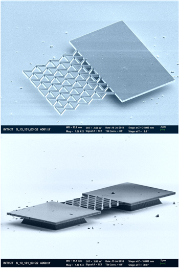
Figure 2. Cantilever and bridged re-entrant auxetic structures obtained.
Download figure:
Standard image High-resolution image
Figure 3. Cantilever and bridged chiral auxetic structures obtained.
Download figure:
Standard image High-resolution image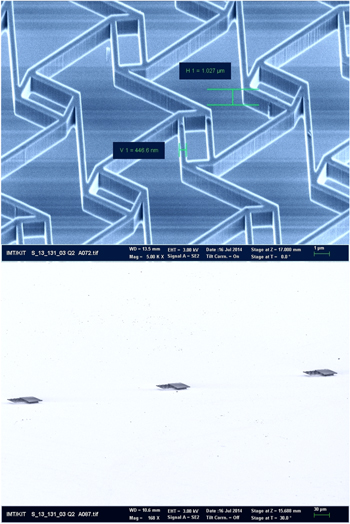
Figure 4. Detail of manufacturing precision measured upon a chiral auxetic structure (upper image). Overview of several structures manufactured using a single wafer (lower image).
Download figure:
Standard image High-resolution imageComparable precision has only recently been obtained with three-dimensional auxetic geometries using DLW (NanoScribe GmbH), currently the most precise additive manufacturing technology commercially available (Bückmann et al 2013, Hengsbach and Díaz Lantada 2014). Both procedures, the subtractive based on DRIE and the additive based on 3D photopolymerization by DLW, are complementary and enable the manufacture of different types of micro-auxetics. The additive procedures allow for the development of complex lattice structures with potential for a 3D cell culture, among other valuable applications. However, such processes are slower and difficult to apply for mass production with state-of-the-art resources. The DRIE process can be applied to obtain several hundreds of auxetic microstructures acting upon a silicon wafer of 10 × 10 cm2 in just a couple of hours once the process is adjusted. On the other hand, the additive procedures are slower, mainly aimed at prototyping complex concepts and usually allow for the manufacture of dozens of structures distributed upon a writing area of 300 × 300 μm2 in a process lasting around five hours. To mention an order of magnitude, the DRIE process is currently around 200 times faster than the DLW for the manufacture of micro-auxetic structures. It is also important to note that the typical length/thickness (l/t) ratio of cantilevers attainable by 3D photopolymerization processes reaches typical values of 7 to 10, while the cantilevers obtained in the present study reach l/t values of 40, which is important for the development of resonant microsensors and microactuators. However, the complexity of geometries attainable by DLW, together with the several types of materials that can be processed by such laser-based technology, cannot be matched by the DRIE process. In consequence, working toward the combination of such technologies is also an interesting path of study, which we will try to follow.
3.2. Simulation results
Regarding the resonant behavior of the auxetic structures analyzed using FEM-based simulations, figures 5–8 present interesting results, which are also summarized in table 1. The first ten mode shapes of the cantilever and bridged re-entrant micro-auxetics are presented in figures 5 and 7, respectively. In a similar way, the first ten mode shapes of the cantilever and bridged chiral micro-auxetics are presented in figures 6 and 8. Having a look at the frequencies of the different modes included in table 1 it is important to note that the bridged structures, being more rigid, lead to higher frequencies. The re-entrant prototypes, having a smaller size than the chiral prototypes, also lead to higher frequencies than the chiral structures. In all the cases, the frequencies calculated are in the megahertz range, according to the expected resonance values of the micrometric cantilever or bridged structures. Lower frequencies are linked to the bending modes, while the higher ones involve torsional or combined responses, typically linked to the more energetic modes of metamaterials and structures.

Figure 5. Mode shapes of the micro-cantilever re-entrant auxetic structure.
Download figure:
Standard image High-resolution image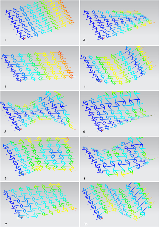
Figure 6. Mode shapes of the micro-cantilever chiral auxetic structure.
Download figure:
Standard image High-resolution image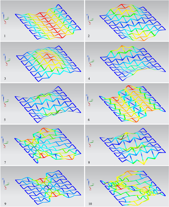
Figure 7. Mode shapes of the micro-bridged re-entrant auxetic structure.
Download figure:
Standard image High-resolution image
Figure 8. Mode shapes of the micro-bridged chiral auxetic structure.
Download figure:
Standard image High-resolution imageTable 1. Natural frequencies linked to the vibration modes of the different structures (MHz).
| Natural frequencies linked to the vibration modes of the structures (MHz) | ||||
|---|---|---|---|---|
| Mode number | Re-entrant cantilever | Re-entrant bridge | Chiral cantilever | Chiral bridge |
| 1 | 2.51 | 12.18 | 0.23 | 1.46 |
| 2 | 3.25 | 16.32 | 0.47 | 1.6 |
| 3 | 5.03 | 16.76 | 0.98 | 2.41 |
| 4 | 7.27 | 17.33 | 1.45 | 2.82 |
| 5 | 14.13 | 22.78 | 1.82 | 3.9 |
| 6 | 15.84 | 26.22 | 2.2 | 4.01 |
| 7 | 15.89 | 31.07 | 2.68 | 4.59 |
| 8 | 17.63 | 34.01 | 3.23 | 4.88 |
| 9 | 17.67 | 38.8 | 3.47 | 6.1 |
| 10 | 18.1 | 40.7 | 3.97 | 6.14 |
To our knowledge, such frequencies are the highest yet obtained for micro-manufactured auxetics, precisely following the geometry modeled with the help of a CAD program. Even higher frequencies reaching values of 15–130 MHz have been calculated for microfoils with periodic foam-based auxetic cores (Munteanu 2010). Applications proposed by Munteanu and colleagues for photonic and sonic crystals may also benefit from a computer-aided designed geometry, and our intention is to further improve the precision of the DRIE process for reaching higher values and for enabling the formation of full band-gaps, needed for controlling the transmission of vibrations over specified frequency bands for active control devices. Combining design-controlled auxetic geometries and quasi-periodic auxetic micro-foams is also an interesting area of study, although our proposal for application presented here is not linked to acoustic and electromagnetic wave control but to advanced tissue engineering scaffolds for interacting at a cellular level.
As previously introduced, during a cell culture process, the uniaxial excitations of an auxetic scaffold may lead to biaxial expansions and compressions of the tissue being grown, which can promote growth and potentially help to control cell differentiation and to improve final tissue viability. Conventional 2D auxetics, obtained by stereolithography or UV-photolithography are not precise enough for interacting at a cellular level, but our DRIE-based manufacturing process leads to unit cells with sizes even lower than those of eukaryotic cells, hence enabling real interaction at a cellular level. A possible application, linked to a resonant sensor for monitoring cell growth and tissue formation processes, has been analyzed with the help of FEM-based modeling, and some important results are presented in figure 9 and table 2, as further discussed in the following paragraphs.
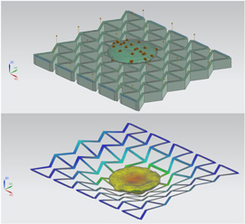
Figure 9. FEM model of a single eukaryotic cell attached to an auxetic scaffold (upper image).
Download figure:
Standard image High-resolution imageTable 2. Impact of a single cell attached to an auxetic scaffold on the natural frequencies.
| Mode | 1 | 2 | 3 | 4 | 5 |
| Freq. without cell (MHz) | 12.18 | 16.32 | 16.76 | 17.33 | 22.78 |
| Freq. with cell (MHz) | 11.02 | 13.64 | 16.03 | 17.19 | 21.43 |
Although the cell model is very simplified, we believe that it is adequate for addressing the impact of cell mass on the resonant frequencies and mode shapes of the bridged re-entrant auxetic and is useful for validating the potential use of these structures as cell-growth sensors. The fact is that the most influential aspect of cell presence upon the scaffold is linked to the overall mass change produced, as cell stiffness is much lower than that of the silicon structures, and therefore its effect on overall structure stiffness is expected to be very low. The related mass increase shifts frequencies to significantly lower values, as can be seen in table 2, which is of interest for the final application and will be of help for forthcoming in vitro validations with the real prototypes and for using precisely monitored cell culture processes. It is also important to note that the presence of the cell importantly changes the form of the different modes and the order of appearance of modes related to bending, torsion, stretching and combined behaviors. In fact, for comparison purposes, the bending mode of figure 9 is the second mode of the cell-scaffold structure, while the bending mode of figure 6 is the third mode of the re-entrant bridge. A frequency shift from 16.76 Hz to 13.63 Hz for the bending mode can be appreciated due to the presence of a single cell, which accounts for around an 18% change and helps to highlight the possibilities of these kinds of devices for monitoring cell growth.
The results are in accordance with those of recent developments linked to arrays of MEMS-based sensors already validated in vitro in which cell mass growth importantly shifted the resonant frequencies to lower values (Park 2010, Corbin 2014). Forthcoming validations will be based on combining advanced cell culture processes with laser-based measurements, as proposed by the aforementioned groundbreaking references. Our current main limitation is the difficult access to micro-manipulation technologies and accessory imaging facilities, which are necessary for the in vitro validation in dynamic conditions, although interesting static results are included further on.
In any case, we believe that our proposed systems present some interesting features when compared to other MEMS-based sensors: first of all, the overall cell culture areas are made of several repetitions of unit cells, which allow for individual interaction with the cultured cells and provide significantly larger cantilevers or bridged culture areas (i.e. 30 × 30 μm2 with unit cells of 4 × 6 μm2) than in previous devices. Secondly, the positive impact of the auxetic structures and the possibilities they open when compared to other possible sensors based on non-auxetic lattice scaffolds is noteworthy, as explained further on.
In fact, the proposed device is more of a self-sensing auxetic-based tissue engineering scaffold than a resonant sensor. Auxetic lattices have been found to be positive for promoting cell adhesion, gene expression and tissue formation (Soman 2012), which may additionally benefit from self-sensing properties. The vibrations of the auxetic lattices may promote bi-axial or multi-axial excitations to the cells and promote cell growth and evolution into tissue, which is different from those typically grown upon non-auxetic lattices.
For instance, cells cultured upon re-entrant cantilevers while exciting the bending and axial modes (modes 1 and 3, respectively) will be subject to bi-axial stretching and compression, which may promote cell aggregations in normal directions. However, if cultured upon chiral cantilevers while exciting modes 4 and 10, aggregations in the form of parallel fibers are expected, according to the mode shapes. Looking at the shape of mode 3 in the bridged re-entrant structure, spherical aggregations in the centre of the scaffold are expected. Mode shapes of the auxetic networks are quite different from mode shapes from non-auxetic lattices; therefore, their use as active tissue engineering scaffolds will promote singular cell responses, aggregations, gene expressions and morphologies of final cultured tissues, as cytoskeleton configurations are affected by roughness, substrate structure, vibratory patterns and other biochemical and mechanical cues of their microenvironments (Thomas 2010, Buxboim 2010). At the same time, shifts from resonances may be used for monitoring the tissue formation process, depending on the excited mode selected for promoting tissue formation. Finally, it is always possible to use the auxetic scaffolds just as support structures for cell attachment and growth forming patterns affected by the scaffold geometry and to only apply excitations for monitoring purposes.
Second resonant mode of the cell-scaffold structure at 13.64 MHz (lower image).
3.3. Cell culture results
Some interesting results from single cells interacting with different auxetic scaffolds, in this case using the re-entrant geometries with the bridged and cantilever options, are shown in the four images of figure 10. The cytoskeletons are stained in green and the nuclei in blue due to having a more complete perception of cell behavior and viability. The rounded forms of the blue nuclei show cells in perfect condition trying to climb, surround and stretch above the auxetic structures. The lower figures show a couple of cells located exactly upon the auxetic grid, and the sub-cellular-sized unit cells of the auxetic scaffolds can be clearly perceived, which helps to validate the potential use of present structures for interacting at a sub-cellular level.
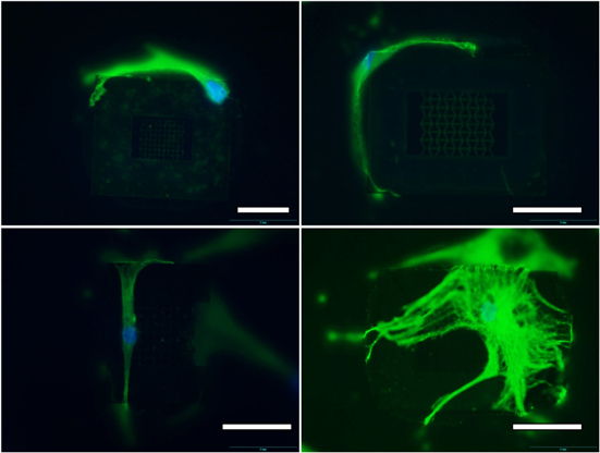
Figure 10. h-MSCs cultured upon different auxetic scaffolds. Different types of interactions between single cells and the smart auxetic structures are shown. Fluorescent dyes: Ph488 (green) for the cytoskeletons; DAPI (blue) for the nuclei. Scale: white bars = 15 μm.
Download figure:
Standard image High-resolution imageCompared to previous groundbreaking cell cultures processed upon auxetic re-entrant and foam-based scaffolds (Soman 2012 and Park 2013, respectively), our structures are at least one order of magnitude more precise and are capable of interacting with single cells, which may promote interesting applications linked to resonant sensors and actuators acting at the cellular level. In fact, the 12 × 12 μm2 auxetic cell culture area, in the case of the re-entrant structure, is even smaller than the conventional PDMS micro-pillars usually used for attaching single cells to precise locations for mechano-transduction studies (Palama 2012).
The images from figure 10 are just some examples that clearly show single cells interacting with the auxetic structures. We would like to mention that in the whole culture area, which included a matrix array of 16 micro-auxtetics manufactured upon a single silicon on an insulator chip, the ratio of damaged cells or those showing apoptotic behavior was lower than 5%, and none of the cells found upon the auxetic microstructures showed symptoms of damage. The stained nuclei are perfectly rounded and when placed upon micro-auxetic scaffolds, cells tend to develop an extended morphology, which can only be observed when the cellular energetic state allows for the polymerization of tubilin in fibers conforming to the cytoskeleton and reaching the cellular surface. Such a state shows the very special affinity shown by cells to the micro-auxetics. Although the micro-auxetics count with sharp edges, cells seem to take benefit from such features, as they use them to crawl upon the micromanufactured lattice structures. The holes of the auxetic lattices do not affect cells in a negative way, and no cells are found to fall through them, as the surface adhesion forces to the structures are much higher than the volume gravitational forces acting upon the cells. In addition, cells are relevantly larger than the unit cell sizes of the auxetic networks, as can be appreciated in the images.
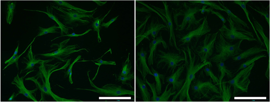
It is interesting to note that when interacting with the auxetic structures, the cells lose their typical more rounded or star-like geometries, obtained in control cultures over gelatin-coated coverslips (figure 11), and tend to migrate around the structure or to climb upon it. Cells stretching to dimensions of up to 50–60 μm and adopting linear or moon-like forms can be appreciated in the images of figure 10. Once upon the auxetic scaffolds, examples of cells spreading to cover areas of 30 × 30 μm2 are also found. These results also help to further discuss about the previous simulations carried out. Clearly, the forms of real cells upon scaffolds with complex geometries cannot be adequately represented by ellipsoid-like simpler geometries, which may be more appropriate for representing their forms in conventional 2D cell culture processes.
Figure 11. h-MSCs controlled upon a control gelatin-coated coverslip. Fluorescent dyes: Ph488 (green) for the cytoskeletons; DAPI (blue) for the nuclei. Scale: white bars = 15 μm.
Download figure:
Standard image High-resolution image
However, it is again important to highlight that the simulation results from the previous section are just aimed at validating the potential use of these auxetic scaffolds for monitoring cell-growth processes. The mass changes induced by single cells upon the scaffolds, either with more rounded or with more linear configurations, are similar. We expect shifts of frequencies in the same order of magnitude as those simulated, although additional dynamic cell culture tests are needed for final validation of the proposed auxetic scaffolds as cell-growth sensors. In any case, cell viability and culture results have helped to demonstrate the viability of the manufacture process, as well as the adequacy of the materials used, for further studies in the field of tissue engineering and repair, taking advantage of micro-manufactured smart auxetic materials and structures.
Our results show that the cells and the micro-auxetics are excellent companions for the artificial development of such complex networks and for potential tissue repair strategies. Toward future studies with similar studies, we would like to put forward some aspects of special relevance: MSCs are cells that remain attached to the vascular networks and constitute a set of co-workers for repairing the damages suffered by different tissues. In case of tissue damage, the hMCSs-seeded micro-auxteic scaffolds may constitute a biocompatible flexible support in order to allow the permeation of nutrients and debris, to promote oxygenation, to enable adaptation and to provide cellular communication systems capable of locally inhibiting the immune system and of activating tissue repair. Last but not least, the hMCSs-seeded micro-auxteic scaffolds offer interesting possibilities to study cellular mechanisms present in different types of tissue. The cell-material interactions may be extended to a triad composed by hMSCs (micro-auxetics) endoderm/exoderm-derived cells for studies linked to complex tissues and organs.
4. Conclusions
In this study we have presented an improved approach for the development of two-dimensional auxetic metamaterials based on the use of DRIE after a high-precision mask fabrication procedure. The quality of the proposed strategy has been verified by the manufacture of an auxetic cantilever and of bridged structures using two common planar auxetic geometries: one re-entrant and one chiral. The prototypes obtained help to validate the process after designing strategies to solve state-of-the-art limitations and to highlight its precision, reaching nanometric detail, and its adequacy for obtaining high ARs. The potential of the manufactured structures for the development of resonant structures, which may be applied in high-precision sensors and actuators, has been analyzed by means of FEM-based simulations, showing resonances in the megahertz range, which have been adequately documented. A final application example linked to monitoring cell culture processes upon auxetic scaffolds has been also proposed and analyzed by similar computational procedures.
The in vitro validation using h-MSCs provides interesting results and highlights the suitability of the manufacturing process and of the materials used for obtaining auxetic scaffolds capable of interacting at the sub-cellular level. We believe that our results show the most precise auxetic scaffolds, upon which cells have been cultured with success.
Acknowledgements
This work was carried out with the support of the European community. We appreciate the support of the European Research Infrastructure EUMINAfab (funded under the FP7 specific programme Capacities, Grant Agreement Number 226460) and its partner, the Karlsruhe Institute of Technology. We also appreciate the continued support from the Karlsruhe Nano Micro Facility (KNMF). We are also grateful to Dr Dieter Maas and to Dr Thomas Schaller for their kind help and support in the KNMF 2013-010-001672 and 2012-009-001150 proposals. We are also grateful for the detailed review and for reviewers' comments and improvement proposals, which have helped us to incorporate interesting references to take into account relevant issues and to enhance overall paper quality.