

Abstract
Resistive flex sensors can be used to measure bending or flexing with relatively little effort and a relatively low budget. Their lightness, compactness, robustness, measurement effectiveness and low power consumption make these sensors useful for manifold applications in diverse fields. Here, we provide a comprehensive survey of resistive flex sensors, taking into account their working principles, manufacturing aspects, electrical characteristics and equivalent models, useful front-end conditioning circuitry, and physic-bio-chemical aspects. Particular effort is devoted to reporting on and analyzing several applications of resistive flex sensors, related to the measurement of body position and motion, and to the implementation of artificial devices. In relation to the human body, we consider the utilization of resistive flex sensors for the measurement of physical activity and for the development of interaction/interface devices driven by human gestures. Concerning artificial devices, we deal with applications related to the automotive field, robots, orthosis and prosthesis, musical instruments and measuring tools. The presented literature is collected from different sources, including bibliographic databases, company press releases, patents, master's theses and PhD theses.
Export citation and abstract BibTeX RIS
1. Introduction
Flex sensors (or flexion or flection sensors, from the Latin flectere, 'to bend', also known as bend, bendable, angular displacement or flexible angular sensors) convert the change in bend to an electrical resistance variation, that is, they convert a physical energy into an electrical one.
Generally, we refer to flexion when considering the variation of a physical position that shortens a joint angle, even if the involved sensor is thereby extended, or straightening, which is the opposite mechanical movement. In an anatomical joint we consider the physical point of connection between two (or more) articulating bones but, generally speaking, the joint can be a point at which parts of an artificial structure are joined.
In general, measurements of flexion and extension can be provided by different kinds of sensors capable of furnishing direct or indirect measures of angle values. For example, the optical fiber Bragg grating sensor [1, 2] or the inertial measurement unit (IMU) family, comprising accelerometers [3, 4], gyroscopes [5], magnetometers [6] (or, preferably, combinations of these such as a tri-axial accelerometer with a tri-axial magnetometer [7], or two accelerometers and a gyroscope [8]). IMUs are a valid alternative for measuring angle variations, but they suffer from a basic problem due to cumulative integration drifts around the vertical axis. Alternatives are provided by electrogoniometers, which still suffer crosstalk problems [9], and electromagnetic motion capturing systems, such as the ones produced by Polhemus or Ascension [10], whose correct usage requires an electromagnetic free environment. Other possibilities are represented by elastic sensors [11], surface acoustic wave (SAW) sensors [12, 13], and polymeric stretchy capacitors (by Stretchsense, Onehunga, Auckland), but without meaningful support from the literature since their full properties are still under investigation.
Currently, video/optical coordinate capturing systems [14–16] represent the gold-standard apparatuses for measuring angular displacements, but they are bulky and too expensive.
In such a situation flex sensors represent an interesting alternative and can be applied not only to strictly measure the angles assumed by joints, but also to measure shapes, for instance, the contours of the shoulder [17], or any fixed/variable surface geometry [18, 19].
Among flex sensors, a special role is played by the passive resistive ones. They are made of electrically conductive patterns, engineered on top of or within a flexible substrate (schematized in figure 1) that is able to tolerate bending, vibration, thermal shock (within normal thermal excursion of usage) and stretching, without concern for electromagnetic interference or sensor occlusion.
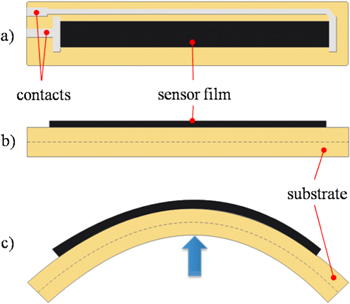
Figure 1. Scheme of a resistive flex sensor. (a) Top view: electrical contacts in grey, conductive film in black. (b) Lateral view: conductive film, in black, on top of a substrate, in a lighter color. (c) Bending the substrate causes a mechanical stress of the conductive pattern that leads to a change in its electrical resistance.
Download figure:
Standard image High-resolution imageThere is a growing interest in this kind of sensor, evidenced by an increasing market and witnessed by the number of released patents in recent years (figure 2).
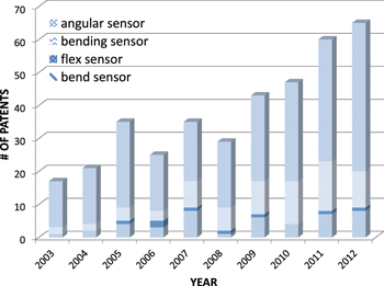
Figure 2. Number of licensed patents regarding flex sensors and their applications, in the years 2003–2012. The bar graphs reveal a trend that shows an increasing interest and market for this kind of sensor. Information was obtained from search engines of patents, but the same kind of sensor was found under synonymous adjectives: 'angular', 'bending', 'flex' and 'bend' sensor.
Download figure:
Standard image High-resolution imageThis survey focused on resistive flex sensors (RFSs hereafter) that are being increasingly applied in ever-widening fields, particularly centered on human body tracking and artificial devices (figure 3).
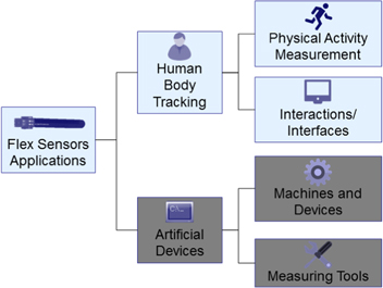
Figure 3. Tree diagram representation of the applications of flex sensors. Sections 5 and 6 consider the applications in human body tracking, particularly devoted to physical activity measurements and to the applications devoted to human interactions/interfaces with machines. The applications for artificial devices are treated in section 7.
Download figure:
Standard image High-resolution imageThere are several different RFS architectures and here we deal with the ones that are restricted to single axis bend sensing. We provide a review of their principle and manufacturing in section 2, their properties and models in section 3, and the way they are electronically interfaced in section 4. Section 5 is dedicated to some fundamental applications concerning biometric measurements of upper limbs (finger, hand, wrist, elbow and arm), head and torso (neck, lung, larynx, chest and back), muscle shape and lower limbs (knee, leg, ankle and foot). These applications are intended for medical purposes (rehabilitation, kinesiology, diagnostic, fitness), for human–machine interfaces, for gesture modeling and recognition. RFSs can be particularly useful in developing systems for interaction with and/or interfacing virtual/augmented reality ambience and for human–computer interaction possibilities. Section 6 is devoted to these aspects.
Finally, RFSs can find applications in a variety of other fields, ranging from measuring systems to musical instruments, from control systems in prostheses and orthoses to control systems in the automotive industry, and so on. Sections 7 and 8 review different applications.
2. Principle and manufacturing
As sensors, RFSs operate on the same principle as strain gauges (flexion of the material induces tension along one side of the bending radius and compression along the other side), but with a substantially greater sensitivity.
RFSs are fundamentally based on the variable resistive characteristics of a conductive material, typically in an ink form, so as to become a part of that conductive ink business market that had generated about $1.6 billion by the end of 2014, growing to $2.8 billion by 2024 [20]. Recently, new forms such as powder, paste or film ones, have been growing in importance, possibly mixed with a resin, and/or with fillers and/or binders and/or additives, diluted in a solvent or a thinner if necessary, and engineered with different sorts of substrates.
2.1. Conductive component
With regards to the conductive component, the most commonly adopted one is based on carbon elements. We can refer to carbon powder [21–24], ink [25], particles [26], nanoparticles [21, 27], nanotubes [28], or carbon's allotropic form as a graphite [29, 30]. Transition metals can be used too, such as silver [31–35], copper [29], nickel [36], platinum [37], and palladium [38]. Others are electro-conductive rubber [39], carbon-loaded rubber [40], and some conductive polymers such as the ionic metal composite (IPMC) [41], and Poly(3,4-ethylenedioxythiophene) (or PEDOT or sometimes PEDT) [42], whose poor solubility can be partly circumvented with the PEDOT:PSS composite (figure 4) [43].
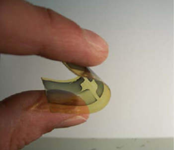
Figure 4. A flex sensor made with composite conductive material (Poly(3,4-ethylenedioxythiophene): PSS or PEDOT:PSS). The figure shows the really appreciable flexible characteristic of the sensor. The dark region represents the conductive pattern. Reproduced from [43], copyright 2009 Elsevier.
Download figure:
Standard image High-resolution imageClearly, the adopted conductive material and the way it is layered determine the basic electrical properties of the sensor. In this way, sensor resistance is highly susceptible to any defects along the conductive surface. This is particularly significant when the conductive material is deposited not in the commonly adopted form of a thin film, but as sensor yarns (i.e. as in [44], where glass yarns coated with PEDOT:PSS were integrated within braided fabric).
2.2. Substrate
The flexibility of the sensor mostly depends on the intrinsic properties of the substrate and its defect-free good adhesion with the conductive component. The substrate can be realized by means of different materials based on polymers, among which the most significant are polyvinylchloride (PVC) [32], polypropylene (PP) [25, 34], polypyrrole (PPy) [22], styrene-ethylene/propylene-styrene (SEPS) [34], and kynar (a brand name for polyvinylidene fluoride—PVDF) [25]. Among polymers, elastomers are adopted due to their elastic properties, so we have silicone rubber [45, 46], polyurethane (PU) rubber [47], and Evoprene™, a thermoplastic elastomer compound [21]. In addition, it is worth mentioning the polyester family, used by several research groups. Such a family includes polyethylene naphthalate (PEN) [29, 35], polymide (PI) [32, 35, 43], which is capable of thermal isolation [36], polydimethylsiloxane (PDMS) [48] of the silicones group, polyurethane [47] (a synthetic resin), Mylar (used to make heat-resistant plastic films), and the most common, polyethylene terephthalate (PET) [25, 32]. During recent years, a number of researchers have even adopted artificial tissues as substrates, so to make the flex sensors 'directly' wearable. We should also mention cotton [33], cotton/Lycra [49], Lycra [22], polyester/Lycra [26], Belltron®/Lycra® [50], tightly woven polyester, nylon fabric [21], and Spandex, which is a type of stretchy polyurethane fabric [31]. Unusual but interesting substrates are paper [30, 32], cardboard [30] or even human epidermis [51].
2.3. Elements engineering
The electrical conductive element(s) can be engineered with the substrate according to different techniques, preferably low-cost to guarantee an affordable final device. Additive systems, headed by general printed electronic systems, are preferred, and strategically considered by several important companies such as BASF SE, Emagin Corp., Kovio Inc., Toppan Forms, Sipix Imaging Inc., Printechnologics GMBH, Polyic Gmbh & Co. Kg, Novaled AG, Nano Solar Inc., Aveso Displays, Blue Spark technologies, and E Ink Holdings Inc.
Fundamental printing methods are ink jet [35, 52], spray, screen [32], flexographic or gravure [53, 54] and transfer printing [55]. Other systems include photonic flash sintering [29], injection by air pulses [46], melt-mixing [21], percolation [56, 57], and electrochemical polymerization [43]. With respect to manufacturing standard methods, the aforementioned ones allow lower costs, shorter execution times, and the possibility of a pattern on both flat and even curved substrates, and with every sort of geometry, in an array [58] (figure 5(a)), matrix [59] or shaped form [60], or with any other distribution of conductive areas (figure 5(b)).

Figure 5. Flex resistor sensors with a nonstandard distribution of the conductive film. (a) This figure represents an array of three flex sensors (black rectangular areas) manufactured on a unique substrate. The conductive area of the third flex sensor (the one on the right of the figure) has got a middle 'slot' used for alignment purposes [58]. (b) This picture shows a shoe sensor using three sensor elements to sense when and how the foot hits the ground and how the balance and weight transfer happens (courtesy of Flexpoint Inc.).
Download figure:
Standard image High-resolution image2.4. Coating
RFSs can be made without any coating, known as base, bare or uncoated flex sensors, or a final protective coating can be realized by means of a dielectric epoxy coating [32], silicon rubber [27, 46] or simply adhesive rubber [25], polyester or polymide (Flexpoint Inc.). The coating material usefully provides an overall chemical and mechanical protection.
2.5. Working principle
The concentration by weight of the conductive material with respect to the substrate, and its nature (powder, ink, paste or film), play key roles in the final electrical performances of the sensor. In the most common case of a conductive ink made of carbon particles in a binder, a cracked ink surface (figure 6) allows the cracks to open when placed in tension, due to the elongation of the material surface, causing the crack faces to separate and so increasing the resistance. When the material is returned to the flat position, the distance between the cracks' faces shrink and the resistance decreases. Cracks do not really repair themselves but their relative distance changes according to the bending angle; this makes the binder system in the ink critical, since if the bond is weak the ink flakes off the substrate and the sensor becomes useless.
Figure 6. Scanning electron microscope (SEM) image of a series of micro-cracks on the conductive film. Such discontinuities become larger with bending, typically in a submicrometer range, and are responsible for the increase in the electrical resistance of the flex sensor.
Download figure:
Standard image High-resolution imageWithout micro-cracks, the sensor offers better durability but lower resolution [61]. Given such behavior, the conductive material has to be placed upon the convex side of the bent surface, otherwise flexion would act in compression rather than in stretching. To obtain a bidirectional behavior, that is, the capability of the sensor to change its resistance when bent both back and forth, the conductive material has to be engineered on both surfaces of the substrate [62]. Or bidirectional sensing can be realized by two back-to-back flex sensors [63–66].
Given all the aforementioned characteristics, the electromechanical properties of RFSs can be tailored to meet the needs of many specific applications.
2.6. Manufacturers
Originally, this type of sensor was developed by AGE Company (Abrams/Gentile Entertainment, New York) only and used in the so-called 'PowerGlove' (by Mattel), a sensory glove capable of measuring finger flexion. For some years there was no way of obtaining some of those sensors unless they were removed from the glove itself. Nowadays, RFSs have been commercialized by different brands, among which are Spectra Symbol (www.spectrasymbol.com, with 'FlexSensor4.5' commercialized by the online retail store Sparkfun.com), Abrams-Gentile (www.ageinc.com), Flexpoint Sensor Systems, Inc. (www.flexpoint.com, with the proprietary 'Bend Sensors®' carbon/polymer based ink) and Images SI Inc. (www.images.com, that furnishes the 'Bi-Flex Sensors™' capable of bidirectional behavior). The RFSs mostly commonly adopted and reported in the literature are those produced by Flexpoint Inc. and Image SI Inc. (figure 7).
Nowadays, the typical commercial RFS can be purchased for as little as tens of US dollars.
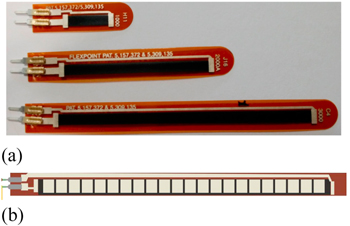
Figure 7. (a) Three flex sensors, by Flexpoint Inc., with different lengths of 1, 2 and 3 inches (2.54, 5.08 and 7.62 cm), respectively. The blue plastic parts, visible at the bottom of each sensor, act as protective layers for the electrical contacts. (b) The 4.5 inches flex sensor by Inage SI Inc. Courtesy of Flexpoint Inc..
Download figure:
Standard image High-resolution image3. Properties and models
The main electrical characteristics to take into account for RFSs are sensitivity, repeatability and reproducibility of the measurements, recovery time, linearity in response, and power consumption.
The main mechanical properties to take into account are weight, pliability, strength, robustness and reliability.
Other valuable characteristics are its scaling features, its functionality in harsh environments, ease of removing/replacing/applying, and cost effectiveness.
3.1. Electrical characterization
An RFS is a passive device which does not require any bias or source power to work. When the sensor is flexed the substrate is consequently compressed and the conductive layer stretches, thereby increasing the overall resistance up to a maximum value corresponding to the maximum measurable angle of deflection. The electrical value can have a reactive (in particular capacitive) component, as previously demonstrated with an accurate RLC model (figure 8(a)), which can be developed to fit the electrical response of flex sensors under fast deformation movements. However, this reactive component has a negligible value (figure 8(b)) [67].
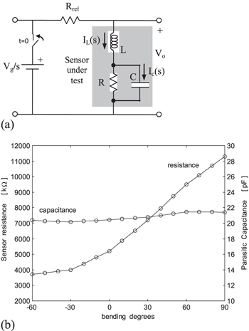
Figure 8. (a) Schematic representation of the equivalent circuit adopted to simulate the sensor electrical behavior under resistance variation. (b) Plot of the sensor resistance/parasitic capacitance vs bending angle degrees [67].
Download figure:
Standard image High-resolution imageFocusing on the real (resistive) component, an RFS can be characterized in terms of its resistance value R versus the flexing/bending angle ϑ (R versus ϑ), practically realizable by wrapping the RFS around a pivot with a fixed curvature radius [68–70] or on top of a varying-curvature surface [19, 71–73]. In general, the smaller the radius r of curvature and the more the involved conductive area of the sensor in the deflection is, the greater the RFS electrical resistance R will be. In order to give the full picture, it is also possible to relate the RFS resistance R versus the applied bending force F (R versus F) [74], or to the portion of the total length of the RFS (effective length, l) effectively subjected to the flexion/bending (R versus l) [75]. Attention has to be paid to drift problems, since an RFS can vary its resistance over time even when in mechanically stationary conditions [19, 71, 76].
Many authors utilize an RFS in series with a fixed resistor, thus forming a voltage divider, reporting RFS characteristics in terms of output voltage V (rather than resistance R) versus bending angle ϑ (V versus ϑ) [70, 76–81], and in this way strictly linking the result to the value of the fixed resistor, as investigated in [82].
The most interesting characterization relies on the 'R versus ϑ' curve which will be discussed further in section 3.1.2.
3.1.1. Characterization setups
Generally, manufacturers furnish a 'qualitative' rather than 'quantitative' 'R versus ϑ' curve, so that ad hoc electrical characterization is mandatory.
The measurement setups that have been used in the literature to characterize RFSs vary from being completely manual to fully automatized. In its easiest implementation, the setup can be realized by means of a specially designed fixture that allows the sensor to be flexed in arcs [38, 72], or by means of a simple cylinder with a fixed diameter [76] for the sensor to be wrapped around, or through a bending apparatus with a hinged joint controlled through a goniometer [83]. These setups require tedious time-consuming procedures and are potentially sources of inaccuracy [84]. An accurate measure requires a fully automatic bending apparatus equipped with a hinged joint that is able to rotate [76], or a pushed/pulled sliding trolley on a linear guide moved by a stepper motor [73].
3.1.2. Resistance profile and new setup
As already mentioned, measurements can be carried out by bending the RFS around a varying-radius pivot (e.g. cylinders with different radii), or around a fixed-radius pivot (e.g. a hinge).
In the first occurrence (pivot with a varying-radius r or, equivalently, curvature k = 1/r), different works demonstrated an exponential trend decreasing in resistance as the curvature k was increased (respectively k within: 0–25,4 mm−1 [71]; 285–1500 mm−1 [72]; 0–0.02 mm−1 [73]), with negligible hysteresis. As a noticeable result, the work in [40] found that the 'R versus r' curve is not meaningfully affected if the RFS does not perfectly adhere to the pin around which it is wrapped during measurements, therefore the 'perfect adhesion' of the RFS on top of the joint being measured is not a mandatory requirement.
In the second occurrence (pivot with a fixed radius), the 'R versus ϑ' curve presents a nonlinear trend, but different authors report different types of nonlinearity. In [68], the nonlinearity was found to be polynomial, within the 0°–170° range, with very low sensitivity for angles of <45°. In [25], the authors found a second-order polynomial behavior within the 0°–100° range, without evidencing low sensitivity for any particular angular range. In [85], the nonlinearity curve fitted two different second-order polynomial curves for angles <30° and >30°, respectively, with very low sensitivity for angles <30°.
In order to take 'a step ahead' towards a reliable answer regarding the kind of nonlinearity, here we have meticulously carried out measurements on several RFSs, adopting a fully automated and highly suitable mechanical setup (figure 9). It was used to ten times, iteratively bending different RFSs inward (0°–120°) and backward (120°–0°) to known angles and measuring resistance outcomes in 5° steps.
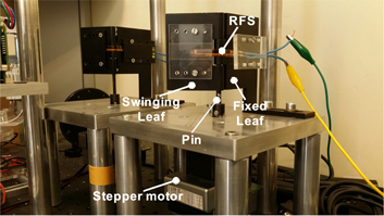
Figure 9. Fully automatized setup. The RFS bends according to rotation of the stepper motor that controls the swinging of one leaf of the hinge. In the foreground the 1.2 cm pin hinge, in the background the 0.8 cm pin hinge.
Download figure:
Standard image High-resolution imageThe core of the setup was an anodized metal 0.1 μm-tolerance mechanical hinge, which allows the swinging motion of one leaf with respect to the other, fixed to a supporting base. The mobile leaf is welded to a cylindrical pin with the axis of rotation of the hinge. We utilized three tailor-made hinges differing in pin diameter (0.8 cm, 1.0 cm and 1.2 cm). The swinging motion was realized by means of a stepper motor (PD series by Trinamic, Hamburg, Germany) fixed to the cylindrical pin so that its rotation moves the unfixed leaf. The entire setup was fixed to a professional passive dumped optical bench (Newport Corporation, CA, United States) to avoid any vibration affecting the measurements [86].
Every 5° in bending, the swing was paused for 2 s, during which six resistance values were collected via a multimeter (34405A by Agilent, Santa Clara, CA, USA) and averaged to minimize noise errors. Both motor and multimeter were managed by a pc-running routine in Labview (system design software by National Instruments, Austin, TX, USA), in order to automatize the setup.
We carried out tests on several samples by Flexpoint Inc. and Images Co., with different lengths (1, 2, 3, and 4.5 inches), and which were differently overlaminated (polyester, polymide and no-overlaminated respectively).
The results obtained from sensors by Flexpoint demonstrated some variability even among sensors of the same type and length, but with a unique common trend. As an example, figure 10(a) shows the behavior of seven twin samples by Flexpoint. They were 2 inches long, not overlaminated, tested on a 0.8 cm pin, and range resistance differences among sensor results were evident. However, figure 10(b) shows a similar trend for the resistance values when normalized. Similar considerations result for measurements made around hinges with pins with different radii (0.8 cm, 1.0 cm and 1.2 cm, respectively), as the example of figure 10(c) shows.

Figure 10. Electrical resistance versus bending angle characteristics of seven 2 inch Flexpoint not-overlaminated sensors, wrapped around a 0.8 cm fixed pivot in (a) absolute and in (b) normalized resistance values. These behaviors reveal that the sensors present more evident sensibility over 30 degrees in bending; (c) 2 inch Flexpoint, not overlaminated, sensor wrapped around different pivot sizes. These behaviors indicate the sensibility increases inversely with curvature radii (as reasonably expected); (d) 4.5 inch Images sensor demonstrating a pretty linear behavior.
Download figure:
Standard image High-resolution imageIn all the occurrences, inward and backward resistance values succeeded in being superimposed, even after loading and unloading of the samples under test, in a way that that no hysteresis could be measured because they are 'embedded' within the 'natural' standard deviation of the measures. We found a slow but quite linear resistance increase for bending angles of less than about 30° (R2 > 0.891), while a rapid and linear increase in resistance occurred for angles greater than 30° (R2 > 0.994), with a sort of 'piecewise' behavior. However, the 'R versus ϑ' curve of all the RFSs by Flexpoint can be usefully approximated by a quadratic polynomial curve (R2 > 0.999). In a recent work we demonstrated how a nonlinear 'R versus ϑ' curve behavior of RFSs cannot depend on the mechanical features of the RFS but strictly depend on the electrical ones [87].
Interestingly, there are some solutions which can be implemented to linearize the nonlinear behavior, at least within the 0°–90° range, as realized in three different works. The first solution consists of fixing a thin polyvinyl chloride (PVC) foil over the sensor carbon layer and realizing a current divider with a parallel resistance [88], leading to a linear regression coefficient of R2 equal to 0.9915. The second solution consists of cutting the original rectangular sensitive part of the sensor to obtain a triangular shape, which allowed a linear regression value of R2 up to 0.9893 [86]. The third solution considers other shapes of the RFSs, rather than the standard rectangular one, determining the kind of strip geometry which can lead to the maximum linearization [89].
In contrast to the RFSs by Flexpoint, the RFSs by Images demonstrated an inborn linearity, with R2 up to 0.997 (figure 8(d)). However, this advantage is paid for in terms of a lower sensitivity since the resistance roughly 'only' doubles going from flat to a 90° bend angle, compared to the resistance of the RFSs by Flexpoint, which varies up to thirty times. As a result, the RFSs by Flexpoint are better suited to applications which require higher sensitivity, and RFSs by Image are better suited to applications where the linearity is mandatory.
Only one work investigated sensor resistance variation versus applied force, obtaining a 'R versus F' curve [74]. It realized flow measurements by means of 4.5'' sensors by Spectra Symbol and determined a cubic fitting curve for forces within the 0–4 N range.
In general, RFSs are used at room temperature conditions, but for particular applications when the temperature can meaningfully vary, the RFS resistance R behavior with respect to the temperature T ('R versus T' curve) must be taken into account. The work in [25] addressed this problem, working with indigenously made silicon-overlaminated RFSs, based on carbon electrically conductive ink engineered onto polyester plastic sheets. The authors found a 30% resistance variation with temperature increasing from 40 °F (4.4 °C) to 120 °F (48.9 °C).
3.1.3. Step response decay and measurement uncertainty
RFSs exhibit step response decay, that is, a variation in resistance over time after a step transition to a different bending angle. This response decay depends on the specific RFS of the specific manufacturer. In particular, 4.5'' RFSs by Abrams–Gentile and by SpectraSymbol were found to show high value decay after 30 s, >22% [71, 90] and >31% [71] respectively. RFSs by Flexpoint have decay values depending on the coating (whether present or not) and length. Specifically, two works state that an over-lamination (with polyester or PVC) enhances the RFS signal stability over a time of 30 s so obtaining a value of decay (≤1%) lower than the RFS bare counterpart (>5%) [88, 90]. In [90] the RFS percentage decay after 30 s results worsen with length (0.9% for 4.5''; 8.25% for 3''; 18.20% for 2''), but this result is different to results reported by others (8.9% for 3''; 5.7% for 2''), obtained in [71, 88]. Table 1 summarizes values of decay for different RFSs. In view of the above results, the RFSs with higher decay can be better suited to sense angle changes rather than magnitude angle values.
Table 1. Step response decay after 30 s, for some flex sensors, different in length and coating and from different manufacturers.
| RFS type | length [inches] | 30 s decay [%] |
|---|---|---|
| Abrams-Gentile | 4.5 | 22.19a; 24.4b |
| SpectraSymbol | 4.5 | 31.8b |
| Flexpoint—bare | 4.5 | 0.9a |
| Flexpoint—bare | 3 | 8.25a; 8.9b |
| Flexpoint—bare | 2 | 18.20a; 5.7c |
| Flexpoint—bare/modified* | 2 | 1.0c |
| Flexpoint—polyester | 2 | 0.47a |
*Unplasticised polyvinyl chloride (PVC) foil fixed over the carbon active layer. a[90], b[71], c[88].
As well as any other type of sensor, RFS presents measurement uncertainties, that is, a dispersion of values in determining a bending angle. These uncertainties can originate from the measurement procedure, manufacturing inaccuracy or sensor placement. In particular, commercial RFSs suffer from a sensible layer which can be (more or less) inhomogeneous, and a change in the sensor longitudinal placement, that is, a change in the portion of the sensible area under bending affects the sensor output response [75, 76].
Some solutions have been proposed to reduce these uncertainties, such as the utilization of two sensors at a time to take the same measurement, combining the respective readings [65] with a simple multivariate regression model [91], or the adoption of the extended Kalman filter (EKF) to reduce problems due to sensor noise [80].
3.2. Physico-biochemical characteristics
From a physical point of view, attention has to be focused on the mechanical properties of RFSs, in particular on their weight, durability/robustness and environmental stability.
Manufacturers claim high robustness in their RFSs, stating that they are capable of flexing and extending millions of times. No proofs of such lifetime are provided, but RFSs were nevertheless adopted to measure liquid flow rates continuously for three weeks without maintenance [92], and were used as goniometer tracers for index finger, wrist, and elbow on 21 subjects over the course of six months without requiring replacements [91].
Base RFSs demonstrated aquatic environmental stability when adopted in a test flume, with the intent to map out the flux of dissolved chemicals and solids [93] typically under at most 3 m of water [92]. Stability was not recorded with respect to temperature variations to which RFSs are rather extremely sensitive [25], so we should assume they can be adopted as temperature sensors too.
However, when necessary, environmental stability enhancements can be realized by means of extra protection, obtained by over-laminating or over-molding with a supplementary layer added to the standard sensor coating. This extra protection can also help to reduce the sensitivity to mechanical scratches that can meaningfully affect the electrical properties. However, any additive layer can reduce, even substantially, the sensor sensitivity.
A key question is how the mechanical properties of the substrate influence the electrical behavior of the RFSs. This is to allow some predictability in performances. This aspect has been treated in just one work [87], which demonstrated that the more the substrate is bent the more the resistance of the conductive part increases, in a linear way. Any nonlinearity in the electrical behavior (as treated in section 3.1) is only dependent on cracks in the resistive element during mechanical stress.
From a biochemical point of view, it is interesting to use the properties of RFSs, adopting them under human or animal skin, realizing e.g. a pervasive monitoring implantable device for wireless capsule devices [94] or 'CardioMEMS', which was recently developed [95]. In fact, permanent or semipermanent insertion can provide a better quality of life for those who have experienced severe physical trauma, when it is mandatory to record a stream of data from particular joints so as to continuously monitor reduced motor activities, and/or to drive electromechanical prosthesis. Only one work has addressed this problem, performing in vitro analysis, and it was demonstrated that only specific RFSs (polyimide-encapsulated ones) can be potentially used for this purpose because they showed low pyrogenic effects, with no relevant cytotoxicity, and displayed a low proinflammatory profile [96].
4. Conditioning circuitry
Resistance values obtained from RFSs have to be processed to obtain useful signals for different purposes, so that they must undergo some form of conditioning electronic circuitry. In general, the wider the resistance range and the higher the linearity of the response of the sensors, the more straightforward and less noisy the realization of the signal conditioning circuitry can be, generally made of front-end, signal treating and data transmission electronics. With this in mind, we have to take into account the different behavior of commercial RFSs since, for instance, the Flexpoint ones demonstrate nonlinear behavior but large resistance ranges, while the Image SI ones behave more linearly but with a reduced range of resistance variation.
Suggested front-end circuitry from the manufacturers consists of a simple voltage divider configuration, which has been the most commonly adopted one, as in [25, 62, 91, 97–101], feeding a unit or variable gain op-amp for a high resistance input isolation buffer. The value of the resistor, forming the divider together with the RFS, is suggested from manufacturers to be as close as possible to the base resistance of the sensor. Conversely, a recent work [70] suggests adopting the value of such a resistor equal to the geometric mean between the extreme RFS resistance values, corresponding to flat and maximum flexion conditions respectively, so as to maximize the signal sweep for the maximum allowed flection degrees. A different, but rarely adopted, front-end uses a half-bridge configuration [102] with a balanced supply. According to the aforementioned known temperature sensitivity (see section 3.1), a temperature-compensated front-end circuit can be conveniently adopted by means of a bridge configuration [25, 33, 74, 79, 103, 104]. A recent work suggested an unusual front-end solution where the resistive values of sensors are determined through the time requested to charge a series capacitor connected to the comparator of the adopted microcontroller [85]. Other proposals converted changes in resistance of RFSs to changes in voltage by means of a constant current source [80, 105]. A microcontroller (through a multiplexer if necessary, as in [98]) can treat signals received directly from the aforementioned front-end solutions or from a buffer op-amp [63, 97, 106, 107], or from an instrumentation amplifier [74, 79, 108], eventually filtered [108], so as to make them ready to be further processed by a computer. The microcontroller includes an AD conversion that, considering a maximum flexion range of 120°, can convert to a 12-bit digital value to detect small variations in movements [109]. As examples of microcontrollers, in [110] an MF624 data acquisition card was adopted (by Humusoft, Prague, Czech Republic) which accessed at a sampling rate of 1 kHz; in [111] a rfPIC12C509AG microcontroller sampling at 9600 Hz was used; in [112] a 16C711 PC; in [113] a 18F4550 PIC; in [98] a 16F690 PIC (by MicroChip, Arizona, USA) controlling a front-end multiplexer to acquire signals cycling among 19 RFSs, the same number as in [114] when an ATmega1280 processor, as a part of an Arduino Mega microcontroller (by SmartProjects, Italy) was adopted. Different versions of the Arduino platform were utilized in [75] (the Arduino Uno, with ATmega328 chip), and in [115] (the Arduino Leonardo), while the work in [116] reported on an Arduino microprocessor but no version was provided. The signal treatment can include a comparison to input resistance variation data to the resistance profiling data and compute corresponding output [74].
In general, it is suggested that close attention is paid to the wire connections because, on most RFSs, longer connections can meaningfully increase noise in the AD conversion process.
In order to realize portable systems, it is convenient to adopt a wireless low-power consumption link towards the receiver. Different wireless standard protocols, within local area networks (LAN) or body area networks (BAN), can be suitable for short range wireless communication, realizing what is currently known as the wireless body sensor network (BSN) protocol [117]. However, RFSs are generally adopted for applications with low data-rate requests, which are low in power demand too. Therefore, the most commonly adopted wireless links have been realized via Bluetooth [68], IEEE 802.15.4 [82, 118], ZigBee/XBee [82, 98, 107, 116, 119–122], WiFi [123], standard FM with FSK modulation [112], or via a nonstandard protocol based on ASK modulation [75, 124] or on–off key (OOK) modulation [85].
5. Physical activity measurements
Human body complexity makes the task of obtaining its spatiotemporal information highly challenging, but some of the most relevant applications of RFSs have been oriented toward human body tracking. These sensors allow an unobtrusive, ubiquitous, easy to use, fast, cost-effective, low-power way to track segments of the body, even continuously over extended periods, without reducing freedom of movement. This can be effective both for physical activity measurements and for interaction of the body with the surrounding environment.
Body tracking was introduced for clinical purposes to evaluate the capabilities of human joints (in particular the range of motion—ROM), overall body posture and physical activity in general. A dated work [125] compared the clinical body tracking realized by visual estimation versus goniometry, underlining the high variability of the former and the low accuracy of the latter. These methods are still routinely adopted, but they can be advantageously replaced by the use of RFSs, as demonstrated in kinesiology [91], physiotherapy [126], rehabilitation [59, 102, 127, 128], telehealth [129] or long-term monitoring [130], and in the control of orthoses [105, 106, 131–136] or prosthetic limbs [89, 108, 137, 138].
RFSs have generally been mounted on supportive stretch fabric clothes worn by the users, so as to allow measurements of human physical activity relative to every segment of the body. Because of their small form-factor, RFSs are especially suitable for tracking small body segments, such as fingers, elbows and knees, primarily for one degree of freedom (DOF) movement. Combinations of two or more sensors allow the measurement of multiple DOFs, such as wrist, torso, shoulder and ankle.
The interested reader can find a survey about human motion tracking systems especially developed for rehabilitation purposes, in [127], and a comprehensive analysis of joint structure and function in [139].
The following sections concern the measurements of upper limbs (fingers, wrists, hands and elbows), of head and torso (larynx, thorax, shoulder), and of lower limb (knees, semitendineous muscle, ankles and feet) movements.
5.1. Upper limb
Measurement of the physical activities of the upper limb with resistive flex sensors involves mostly the hand, which is by far the most investigated part of the entire body. The hand is a masterpiece of highly articulated mechanical joints so that measuring its motion is a very challenging matter. Hand data have been generally collected by means of a so called sensory glove (also known as an instrumented, goniometric or data glove), which is a nonobtrusive glove equipped with sensors. The key aspects of such a glove are the sensor placing, the glove material, and the number of DOFs to be investigated, considered in the following.
The most commonly adopted kinematic hand model considers 27 DOFs for the hand [140]. Assuming the joints to be spherical, four DOFs are for the index, middle, ring and little fingers: the metacarpo-phalangeal (MCP), the proximal-interphalangeal (PIP) and the distal-interphalangeal (DIP) joints, capable of three flex/extension DOFs and one abdu/adduction DOF. Five DOFs are for the thumb: the metacarpo-phalangeal (MCP) and the inter-phalangeal (IP) joints, capable of three flex/extension and two abdu/adduction DOFs. Six DOFs are for the wrist (rotational/translational capabilities) (figure 11). Therefore, theoretically, 27 sensors, one for each DOF, are necessary.
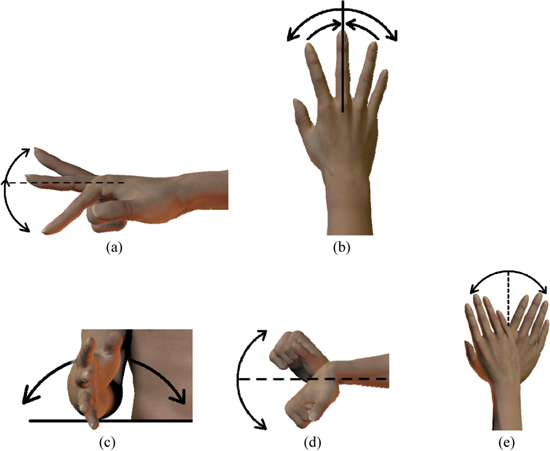
Figure 11. (a) Flexion–extension and (b) abduction–adduction capabilities of the fingers, (c) neutral (between pronation–supination), (d) flexion–extension and (e) radial–ulnar deviation capabilities of the wrist.
Download figure:
Standard image High-resolution imageTo perform finger flex/extension tracking, RFSs are singularly placed upon the dorsal aspect of the finger joints following their movements. Each sensor is embedded in a sheath, sleeve or pocket, made of nylon [141] or Lycra® [88], so as to be free to follow the joint flexion without side drifting, and generally sewn on the dorsal aspect of a glove (one exception can be found in [131], where sensors were applied in the internal part of the glove by means of light-strips). In contrast to flex/extension, measurement of abdu/adduction capabilities of fingers has been a challenging task, due to the difficulty in effectively locating the RFSs. Up to now, two proposals have been considered: 1) laying each sensor along its narrow (few μm) side between two adjacent fingers passing on top of the hand web spaces [131] (figure 12(a)); 2) fixing both ends of each sensor on top of the dorsal part of two adjacent fingers so as to realize a half circle which varies its radius with the splaying of the fingers (figure 12(b)) [88, 142]. The first proposal is mechanically hard to realize, the second proposal obstructs object grabbing actions, and neither proposal has ever been investigated from the point of view of measurement reliability.

Figure 12. Resistive flex sensors are used to measure abduction and adduction capabilities (lateral movements) of fingers. In (a) sensors are placed passing along the top of the web spaces [10], in (b) sensors are placed forming an arc/circle [88, 142].
Download figure:
Standard image High-resolution imageEvidence-based practice shows that the glove must be lightweight, minimally invasive, stretchable, and comfortable. A crucial parameter is the tightness so as to guarantee that the sensors are tightly pressed over the fingers to capture the finest flexion angular change [62]. Different materials have been investigated, mostly Lycra®-based, such as a pliable [78] or stretchable grade of Lycra® [88], a mix of 93% Lycra®/7% Nylon blend [71], a Lycra®/cotton combination (spandex) [79, 141], a polyamide/Lycra® combination [76]. Others are neoprene [102], stretchable velvet [143], silk [144], a lightweight thin leather golf glove [145] and even a sheep skin [131] or a material used by bikers (by Fox Head Inc., Irvine, CA) [110].
However, RFSs can be used without a supporting glove, just inserted into an elastic textile tube anchored using Velcro and thick foam rings to keep them next to the finger [102], or inserted into a thin sleeve attached to the back of the finger with a double-sided toupee tape adhesive [71].
Actually, lateral movements of the thumb have usually been approximately considered only related to the trapeziometacarpal joint, neglecting the ones due to the thumb metacarpophalangeal joint. Without considering the wrist, the model reduces to 20 DOFs. This number can be further decreased by taking into account intra-finger, angle-range and one-axis constraint equations among joints [146], since fingers cannot make any arbitrary movements. Additional reductions are possible focusing only on a limited set of movements not involving all the hand capabilities. Therefore, in the literature sensory gloves have been set up with different sensor numbers.
Just one RFS was used to track a coarse middle finger movement made by the patient to report a perceived pain sensation when subjected to a DigitestTM electric pulp tester [147]. One RFS aided in providing a closed loop control of a limb [148]. One RFS was used between thumb and index fingers to monitor hand closing [149]. One RFS was placed on the dorsal aspect of the forefinger of a glove, utilized as a smart attender calling system for patients capable of activating a voice module flexing the finger so to alert caregivers [150].
Only two RFSs were inserted into a sensory glove for monitoring hand rehabilitation [151] or for driving a prosthetic hand [152].
A therapy system developed for upper arm rehabilitation in children was based on three RFSs on the thumb, index, and middle fingers [102], and three RFSs were sufficient to discriminate grasp movements in [153].
Four RFSs were utilized for the first commercialized glove, 'Power Glove' by Mattel Intellivision, dedicated to the Nintendo game console, and four joint angles were measured for microsurgical procedure analysis [145]. In [110], a glove for bikers was equipped with four RFSs to capture the flex/extension of three digits and the addu/abduction movements of the thumb. Again, four RFSs were adopted in support of the assessment of a finger joint angle interpretation method [154], as well as to develop an electrical stimulation grasp-assistive glove to be used in robotic stroke therapy [141].
Five RFSs were necessary to realize an updated version of the 'Power Glove', named the 'P5 Glove' by Essential Reality Inc., which enhanced the precision of its predecessor, reaching 0.5° in angle, and five RFSs integrated into a manifold system designed for capturing gestures [155], as well as for a finger posture wearable monitor [71].
Six RFSs were integrated into a system to support impaired individuals by allowing them a limited ambulatory function [131], and they were also used to monitor finger flexion and palmar and dorsal flexion of the wrist for neurorehabilitation purposes [76].
Seven RFSs were utilized to design an unrestricted upper-extremity rehabilitation system [79].
Nine RFSs equipped the so-called 'SignSpeak Glove', in addition to 11 contact sensors and one accelerometer, to realize a sign-to-speech conversion [156].
Ten RFSs aided hand gesture recognition projects [157, 158], equipped the so-called 'BabyGlove' to assess hand motion control development in infants [68], and ten RFSs were necessary to design a mastering glove to control robots through hand gestures [159]. In [144], a study tested the astronauts' hand dexterity and mobility during extravehicular activity while dressed in different kind of gloves, with five metacarpophalangeal and five proximal interphalangeal joints recorded by means of ten RFSs. The 'PneuGlove' was a pneumatically actuated glove used to assist an impaired hand to control a virtual hand playing a set of keys [160]. Such a sensory glove provided measurements of each digit by means of ten RFSs, and pneumatic actuation by means of servovalves.
Fourteen RFSs were integrated into a sensory glove system for the assessment of human finger movements in neurophysiological settings [88], and were part of novel array structures in a goniometric glove [58].
Complete sensory gloves with twenty RFSs were used for clinical hand assessment [78], and were utilized in a robotic hand system working under a master–slave configuration [109]. Twenty RFSs were part of a complex sensory glove including 16 tri-axial accelerometers and 11 force sensors too, for arthritis rehabilitation applications [59].
Finally, the 'CyberGlove', by Virtual Technology (San Jose, CA, USA), is a commercial product equipped with 18 or 22 (the number depending on the version, the 22 DOFs including palm arch measures) proprietary sensors, presumably carbon-ink based, furnishing an angle resolution of less than 1°.
Few works report the utilization of a glove equipped with sensors dedicated to the wrist motion capabilities [76, 161, 162], and only one concerns a sensory glove used to measure hand capabilities of small primates rather than humans [104].
Table 2 illustrates a full picture of RFSs embedded in sensory gloves, reporting the number of sensors used, the kind of measurements which have been performed, and the manufacturer companies.
Table 2. The number of sensors that have been adopted in a sensory glove, the glove's purposes (measure of flex/extention and/or abdu/adduction capabilities of fingers and/or wrist), the manufacturing company, and the work in which the sensory glove has been used.
| RFS(s) # | Manufacturer/Reseller | Type of measure | Finger(s)/wrist | Reference |
|---|---|---|---|---|
| 1 | Flexpoint | flexion/extension | middle | [147] |
| 1 | Abrams/Gentile | flexion/extension | index | [148] |
| 1 | Spectra Symbol | abdu/adduction | thumb-index | [149] |
| 1 | Spark fun | flexion/extension | index (onto all joints) | [150] |
| 1 | Flexpoint | flexion/extension | wrist | [162] |
| 2 | Spectra Symbol | flexion/extension | index, middle (onto MCP, PIP) | [151] |
| 2 | Abrams/Gentile | flexion/extension | thumb, index | [152] |
| 3 | Abrams/Gentile & Flexpoint | flexion/extension | thumb, index, middle (onto all joints) | [102] |
| 3 | Images SI | flexion/extension | thumb, index, middle (onto all joints) | [153] |
| 4 | Abrams/Gentile | flexion/extension | thumb (IP), index (DIP, PIP, MCP) | [145] |
| 4 | Spectra Symbol | flexion/extension | thumb (onto MCP, IP) index, middle (onto MCP, PIP) | [110] |
| abdu/adduction | thumb | |||
| 4 | Spectra Symbol | flexion/extension | index, middle (onto all joints) | [154] |
| 4 | Flexpoint | flexion/extension | thumb (IP, MCP) index (PIP, MCP) | [141] |
| 5 | not provided | flexion/extension | thumb, index, middle, ring, pinky | [155] |
| 5 | Abrams/Gentile Spectra Symbol Flexpoint | flexion/extension | thumb, index, middle, ring, pinky (onto all joints) | [71] |
| 6 | Abrams/Gentile | flexion/extension | index (MCP, PIP) middle (MCP, PIP) | [131] |
| abdu/adduction | index-middle, middle-ring | |||
| 6 | Flexpoint | flexion/extension | thumb (IP), index (MCP, PIP, DIP) wrist | [76] |
| 6 | not provided | flexion/extension | index, middle, ring, pinky (onto all joints) | [161] |
| abdu/adduction | (2 x ) wrist | |||
| 7 | Abrams Gentile | flexion/extension | thumb, index, middle, ring, pinky (onto MCP, DIP joints) | [79] |
| abdu/adduction | wrist | |||
| 9 | not provided | flexion/extension | thumb, index, middle, ring, pinky (PIP) wrist | [156] |
| abdu/adduction | thumb-index, wrist | |||
| 10 | not provided | flexion/extension | thumb, index, middle, ring, pinky (2 x onto all joints) | [157] |
| 10 | Flexpoint | flexion/extension | index, middle, ring, pinky (MCP, PIP) thumb (MCP, IP) | [144, 158, 160] |
| 10 | not provided | flexion/extension | index, middle, ring, pinky (MCP, PIP) thumb (MCP, IP) | [68, 159] |
| 14 | Flexpoint | flexion/extension | index, middle, ring, pinky (MCP, PIP) thumb (MCP, IP) | [88] |
| abdu/adduction | thumb-index, index-middle, middle-ring, ring-pinky | |||
| 14 | Flexpoint | flexion/extension | index, middle, ring, pinky (MCP, PIP, DIP) thumb (MCP, IP) | [58] |
| 20 | Images SI | flexion/extension | index, middle, ring, pinky (MCP, PIP, DIP) thumb (MCP, IP) | [78] |
| abdu/adduction | thumb-index, index-middle, middle-ring, ring-pinky | |||
| 20 | not provided | flexion/extension | index, middle, ring, pinky (MCP, PIP, DIP) thumb (MCP, IP) | [109] |
| abdu/adduction | thumb-index, index-middle, middle-ring, ring-pinky | |||
| 20 | Flexpoint | flexion/extension | index, middle, ring, pinky (MCP, PIP, DIP) thumb (MCP, IP) | [59] |
| abdu/adduction | thumb-index, index-middle, middle-ring, ring-pinky |
Sensory gloves are valuable when they guarantee repeatability and reliability of measurements. The repeatability is defined both in terms of range (R, the highest-lowest angle value difference among repeated measures) and standard deviation (SD). The reliability, that is, the degree of consistency between successive measures of the same joint movement, is based on the intraclass correlation coefficient (ICC) value. The best values reported for noncommercial gloves have been R = 3.25°, SD = 1.07° [58] and ICC ≅ 1 [118]. It is interesting to compare these results with the usually adopted method of measurements based on visual estimation and mechanical goniometry. In particular, 40 therapists obtained, with visual estimation, an average of R = 80°, SD = 16.85°, and with a mechanical goniometer R = 7.5°, SD = 1.4° [125]; four student volunteers used a professional mechanical goniometer to measure the ROM of 27 young adults, obtaining an ICC = 0.96 at their best [163].
According to the electrical characteristics of RFSs (discussed in section 3.1), a calibration (and eventually normalization) step is necessary to render the measurements unaffected by the differences in user's fingers, and unrelated by time drifts.
RFSs can also be utilized to measure other upper limb capabilities even if few applications have been developed accordingly. In [164] data from an RFS measuring elbow capabilities were compared to the ones measured by a manual goniometer, and in [165] an RFS realized a monitoring system and data logging of an elbow guard. In [166] an RFS, used to sense elbow movements, integrated a motion-based game control system. Reference [167] reports the correlation between the volitional motor signals and the forelimb movements in rats, measured by means of an RFS.
For completeness, the interested reader can find a comprehensive study of the biomechanics of the upper limbs in [168] and a description of the human fingers ROM in [169].
5.2. Head and torso
RFSs have been used to measure movements related to the head and torso.
We start by mentioning the monitoring of swallowing-related laryngeal movement. Currently, video-fluorography examination is the most widely-used method for detecting aspiration linked to dysphagia. In [170] a noninvasive method was proposed for assessing swallowing function/dysfunction by means of a flex sensor fixed on the skin surface along the midline of the neck. The results demonstrated accordance between data from the video-fluorography system and data from the RFSs.
Four RFSs were placed around the neck to obtain information about head flexion angle in [113], in order to recognize the head position in a project aimed to classify the eye gaze direction, comparing SVM, neural network and decision tree classifier outputs. Thanks to the introduction of the RFSs, at 20° head flexion the authors meaningfully enhanced the accuracy of the classification from 50% to 95%.
A nontrivial matter is the reconstruction of the shape and measurement of the movements of the torso, because of its complex form with capabilities of multiplanar axis motions. The human torso locally changes in curvature radius with movements, which is different to a joint which always presents the same curvature radius. In [171] the aspect was addressed (figure 13), and in [73] RFSs have been demonstrated to be effective for this kind of measurement too.
Figure 13. A matrix of nine resistive flex sensors (five of which are visible in front of the figure) were used to measure the movements of the torso in [171]. Copyright 2011 IEEE.
Download figure:
Standard image High-resolution imageA thorax reconstruction and the record of breathing movements were treated with a series of RFSs placed around the chest of a volunteer [19]. A recent work implemented a network of RFSs to acquire patient-specific thorax boundary information, demonstrating a shape error of less than 6% with respect to the total perimeter [18]. A system made of several RFSs attached to a wearable belt was used to follow the deformation angles due to the foetal movement during the last weeks of pregnancy [130]. A gyroscope and an RFS were placed from the torso to the upper arm in order to measure flex/extension of the shoulder in [149].
However, due to some response decays of RFSs when held in the flex position (see section 3.1), and according to a study that evaluated the performances of different RFSs [83], plastic optical fiber sensors appear to be more suitable for wearable trunk posture sensing, even if the latter is performed with a good degree of accuracy [172]. Other measurement systems were preferred to capture the contour/3D shape of the back for patients suffering from musculoskeletal deformities that require customized medical seating for accommodating orthopaedic deformities. In fact, in a comparative analysis of design concepts, the solution using RFSs was considered as 'unsatisfactory', because of the difficulties in implementation [17].
5.3. Lower limb
Different segments of the human lower limb have been measured by means of RFSs.
We start by discussing the knee, to which a great deal of attention has been dedicated in order to find the most effective system of measurement. In [164], data from a single RFS were compared to the ones coming from a goniometer. The RFS was aligned in the center of the knee joint, with a plastic tube working as a guide to allow the sensor to move accordingly with knee flexion. In [105] an RFS-based goniometer was two-point fixed to two transverse bars, with respect to the limb, for sensing the knee joint movements. In [166] a band provided with an RFS was worn on the user's knee to realize a motion-based game control system. The project in [121] recognized sitting, standing, and walking activities, by means of a resizable RFS band worn on the user's knee, obtaining an accuracy of 81%. In [80] the inner angle of a knee joint was measured by means of two sensors mounted on a supportive cloth. Data indicated slightly different behaviors of the two sensors, so that an extended Kalman filter was adopted to merge the different results. A comparison with data coming from a mechanical goniometer provided a correlation of 0.98, and an error of 6.92°. Anyway, the accuracy obtained with RFSs was lower than the one obtainable by means of inertial measurement units (IMUs), which performed with a range of average error within 0.08°–3.06° [80]. Another limitation was highlighted since the RFS response delay was higher with respect to the rotation times of a knee of a running man at the maximum speed of 10 m s−1 [67]. In any case, the position of the sensor utilized was found to influence the accuracy of the measurement [121].
In order to detect the movements of the leg, RFSs have been adopted not only to follow joint flexion, but also to detect muscle shape changes, as in [138] where the semitendineous muscle was investigated for its large shape changes with walking.
Only one work has been devoted to ankle motion monitoring with RFSs [126], but several works have investigated foot mechanical capabilities integrating sensors in footwear. In particular, two back-to-back RFSs, inserted into an insole underneath the arch of the foot, provided information about flex/extension foot movements [63]. The back-to-back solution of two RFSs was also adopted in [65], where the sensors were differently located, to evaluate flexion at the metatarsophalangeal joint, plantar and dorsiflexion. An RFS was mounted on the insole position of a shoe for plantar flexion evaluation during walking, underlining differences between normal and abnormal walking styles based on pattern recognition algorithms [120]. An RFS was used to measure the movements of a middle toe used as a signal control of a prosthesis in [138]. The signal, of about 150 mV in amplitude, was very clear for stationary settings, but much larger for voluntary flexion than from walking tasks.
6. Interaction/interface applications
RFSs have been applied in realizing human interaction with the environment and/or with other humans, or to realize human–machine interfaces. The applications have been focused on systems capable of proximal or remote control, of virtualizing or augmenting the reality, and of recognizing gestures or assisting human tasks.
In particular, with the aim of becoming more user-friendly, systems are migrating from two-dimensional to three-dimensional input devices. Thus, keyboard and mouse are giving way to new peripherals such as Kinect™ (by Microsoft), Xtion Pro (by Asus), D-Imager (by Panasonic), or Senza3D (by Creative). All these peripherals are based on optical technology, which suffers from low-illumination and occlusion problems, so motivating the alternative adoption of wearable devices, replacing inputs from complicated keyboard sequences and mouse combinations, with natural human motion.
6.1. Proximal/remote control
Proximal or remote control, in a system with RFSs capable of providing information about human motor activities, has enhanced many human activities.
As such, different human–computer interactions (HCIs) can be realized. We start by mentioning the simplest application that, by means of a sensory glove equipped with RFSs, captures users' hand movements to activate corresponding operations during a power-point presentation [119], or to replace mouse functions [101]. In [62], a sensory glove is developed for a project aimed at controlling a robotic manipulator. In [173] some keyboard and mouse functions were replaced by a sensory glove capable of clicking, dragging, rotating, and pointing to an ideal position on the screen, thanks to data collected by RFSs and further classified by means of a k-nearest neighbours (k-NN) classifier.
Other applications have realized a motion control of a motorized object with four wheels [174] or, similarly, of a wheelchair [107, 175, 176] moved on the basis of fine finger movements rather than hand joystick maneuvering.
Enhanced applications were related to the one-to-one mapping of human to robot motion with functional anthropomorphism. These implementations can be realized with different technologies indeed, reviewed in [177] and mathematically formalized in [178, 179]. However, the simplest human motion capture systems, intended to be the first step towards realizing these dexterous manipulations, were built on the basis of five RFSs, combined with potentiometers and accelerometers in [180], and 20 RFSs in [181]. In [182], flex/extension data from a sensory glove, together with 3D-positional data from the Microsoft Kinect™, enhanced fine-point control of the end effector of a simple robotic claw, in a more complex project aimed to help persons with disabilities. In [109] a human operator, by means of a sensory glove, tele-operated a robotic hand system working under a master–slave configuration. The anthropomorphic robotic hand had fingers capable of performing motions including flex/extension, abdu/adduction and circumduction. The angle ranges for both human and robotic hands were considered 'approximately equivalent', but no further explanation was to define this 'equivalence' and no meaningful data comparisons were furnished. Conversely, a work dedicated to space extravehicular activity and based on 14 RFSs [183] argued the feasibility of telemanipulations, demonstrating that state-of-the art sensory gloves perform with errors of 4.6° on average, increasing to 6.5° when replicated by off-the-shelf anthropomorphic robotic hands. A paper was dedicated to a slave humanoid robot having the capability of sensing the environment and responding to human commands [184]. It was teleoperated by a wearable system made by several types of sensors, including RFSs used for measuring the bending angles of elbows and fingers. The work in [185] considered the control of robotic hands in a closed-loop master–slave scheme, where the robotic hand was the slave reacting to orders coming from the sensors integrated into the glove of the human operator as a master.
A completely different telecontrol was proposed in [186], where specific movements performed by patients were measured by means of accelerometers and RFSs fixed on their fingers, and the relative signals sent to a base station unit which provided consistent audio messages to the medical staff.
6.2. Virtual/augmented environment
RFSs have been successfully adopted in virtual and/or augmented environment systems, to realize simple visual feedbacks, virtual manipulations, complex systems to support human motor rehabilitation, and to create more immersive digital games.
In particular, RFS-based sensory gloves were used to measure the hand dexterity of both expert and novice surgeons, in order to discriminate their ability and to provide an objective surgery evaluation method [187]. The hand movements were replicated by two different virtual avatars on a computer screen, so as to provide a visual feedback to the novice about the differences of his/her gestures and the gestures of the expert (figure 14).

Figure 14. (a) The sensory glove provided with resistive flex sensors was used to compare and (b) visualize the hand dexterity of the user ('ghost' avatar) with respect of the hand movements of an expert ('on top' avatar) [187]. Copyright 2011 IEEE.
Download figure:
Standard image High-resolution imageA certain degree of interactivity was obtained in virtual manipulation systems realized on the basis of RFSs. In [188] a 3D virtual osteotomy was implemented, with a surgeon driving a scalpel virtually held in a digital gloved hand equipped with RFSs. After that, real-time computer graphics CAD/CAM applications interpreted the flexion angles of the finger joints, measured by means of the 'CyberGlove' (see section 5.1), for novel multidimensional interaction devices [189]. Again, the 'CyberGlove' supported full hand posture estimation for a project dedicated to the realization of a real-time interaction with a virtual rigid objects system [190]. In [191] virtual prototypes were manipulated and modified on the basis of the hand gesture inputs, measured by sensory gloves, for a gesture-based augmented reality design. Jung and colleagues recognized that the sensory glove plays a key role in the so-called 'egocentric' virtual interaction techniques [192], and Ma and colleagues proposed the application of RFSs and sensory gloves in 3D animation for forensic visualization [193].
A virtual ambience was created to motivate children during pediatric motor rehabilitation, by means of a system based on RFSs for measuring thumb, index and middle finger movements, converted into virtual object manipulations on a screen [102]. Similarly, a low-cost viable hand rehabilitation system was developed within an augmented reality system [13], and a rehabilitation game supported the upper extremity movements recorded by means of RFSs [194].
An RFS-equipped band worn by the user on his/her elbow and knee, and an RFS-equipped belt on his/her waist, enhanced the motion control for a ludic virtual ambience [166], while the same kind of sensors were adopted to record movements of a user standing on a wobble board, in order to provide commands useful to control a digital game [195]. In [160], subjects with chronic hemiparesis exhibiting mild to moderate hand impairment were helped to play a virtual keyboard by means of a sensory pneumatically actuated glove (with RFSs and servovalves), named 'PneuGlove'. These subjects demonstrated statistically significant improvement in motor task performance after 3 × 18 h-long sessions per week for six weeks.
For completeness, the interested reader can find a review of interaction techniques in virtual environments in [192].
6.3. Gesture recognition, assistance and interpretation
Humans use their hands with a high degree of dexterity, to grasp and manipulate objects, to execute daily tasks, or even to perform body-language-based nonverbal communications. Currently, this dexterity can be measured by means of webcam-based tracking contours systems. For examples, smart TVs allow us to change channel or to vary the volume with a motion of the hand; some tablets allow music browsing by the user waving their hand. RFSs might open new commercial applications, in particular when integrated into systems useful for motor activity recognition and evaluation, for gesture assistance and interpretation, and for character set and sign language interpretation.
In [76] an RFS-based glove was developed to capture the details of grasping an object, which was useful for clinical practice and rehabilitation settings. The glove reliability was determined by ICC values ranging between 0.84–0.92 and the accuracy error was ±5°. Another work estimated the movements of three fingers during the grasping of an object, including principle component analysis (PCA) to minimize the dimensionality of the dataset [99].
A very challenging application is the measurement and analysis of hand coordination in surgical and microsurgical practice evaluation. A system based on a sensory glove and classification algorithms might score a surgeon's manual skillfulness better than the judgment of experts, which can be biased or prone to human error. In [196] the author developed a glove equipped with six RFSs and nine inertial measurement units, to capture hand gestures in a neurological simulation environment. In [145] a sensory glove was used to measure the angular flex/extension movements of the interphalangeal joints and the grasping pressure of the hand, to analyze microsurgical hand coordination patterns. Similarly, in [197, 198], a glove utilizing fourteen RFSs was used to determine the typology of surgical gesture by assigning it to a predefined class.
Fingers and whole hand movements can be recognized with some differences by means of vision-based analysis, as reviewed in [199], or by means of data acquired with RFSs, as in [200], to realize a gesture-based interface to control household equipment.
RFSs can be used in electronic systems capable of interpreting a character set, so as to help the communication of speechless users. The characters of the American sign language alphabet were acquired by means of a glove with 21 sensors, out of which nine were RFS, and PCA was used to classify the real time input data for feature extraction, with an accuracy of 95% [156]. In [201] the accuracy was equal to 95.13% for the recognition of 42 static hand gestures by means of a neural network classification algorithm receiving a combination of data from a camera-based system and a commercial 5DT data glove (by Fifth Dimension Technologies, Irvine, CA, USA) equipped with 14 RFSs.
The conversion of the Spanish sign alphabet into voice and writing representation was realized by means of a glove equipped with ten RFSs, implementing the discrimination of signs by means of four different multilayer perceptron neural networks, with a classification accuracy of 97.39% at best [202]. In [203] a glove with five RFSs was developed to map bend measurements to the American sign language alphabet, with the user maintaining a static posture for two seconds to improve recognition. A 3D accelerometer was added to a glove with five RFSs in order to add the motion and orientation of the hand to the finger bending measurements and the system was validated with data from nine speech-impaired subjects [200]. A supervised clustering classifier yielded an accuracy of 91.53% for subject-specific models, and an averaged accuracy of 95.34% across subjects. Another work proposed a portable system consisting of an RFSs-based glove able to discriminate up to 243 messages [204]. A similar work was dedicated to the conversion of finger-spelled words into a language processing module, phonetically transcribing each phoneme of the related word of the Malay language [205]. In [206] a real-time system was realized that was capable of recognizing static hand gestures corresponding to the Italian manual alphabet of sign language. Each gesture was mapped onto the corresponding alphabet letter by comparing three different classifiers, namely support vector machines, Mahalanobis distances and Euclidean distances, obtaining an accuracy of >90%. A complete set of 26 characters were classified, with an accuracy of 95%, by means of a glove equipped with fourteen RFSs and a neural network classifier, in [207]. A set of 31 static gestures were recognized, with a classification accuracy ranging between 77.42% and 99.61%, from a South African sign language dataset, adopting the Levenberg–Marquardt training algorithm and neural network classificatory [158]. A reduced set of six words was recognized using the movements of only two fingers and fuzzy logic as a classifier, in [208]. A recent work mapped finger bend data, coming from ten RFSs, into a character set, by implementing a minimum mean square error-based classifier, with a text-to-speech conversion realized on an Android phone [209]. The work proposed in [210] developed a pair of 'gesture vocalize gloves', equipped with five RFSs along the length of each finger and the thumb. Data from sensors were compared to a library with a list of known postures, to assign a particular character to a particular gesture.
More complex is the understanding of dynamic hand and finger configurations, with respect to the aforementioned static ones, to realize conversions of sign languages into speech, and not only into characters. The work in [157] provided the first approach with the classification of eight dynamic gestures, in addition to 47 static ones, of the Taiwanese sign language. The idea was to reduce the problem from 3D to 2D patterns, projecting the sequence of a hand gesture into a 2D trajectory, and then turning a gesture recognition problem into a hand-written characters classification. The work realized in [211] classified a set of 2000 dynamically-executed hand gestures of the Italian sign language, on the basis of a fifteen RFSs-based glove and on wavelet analysis (WA) plus support vector machine (SVM). The accuracy was 86.4%, incremented to 98.8% when adopting artificial pauses between gestures.
In [212] a pattern matching technique was used to implement sign language tutoring rather than a gesture sign interpretation. Animated 3D models from four teachers, performing 65 common gesture signs, were replicated by ten trainees obtaining an average accuracy of 93.8%. The use of a sensory glove, incorporating ten RFSs and ten tactile sensors, was investigated in [213] to assist children learning the Auslan sign language.
The study reported in [116] empowered the user to figure out for themselves the information they want to capture by means of a set of sensors, and utilize that information in the developing of new applications for personal informatics. The study found the most effective sensors to capture helpful data in the daily life context to be the simple light sensor, the sound sensor, the RFID reader and the RFS. In [214], mute people were assisted to vocally express themselves by means of a system that, based on the amount of bending exerted on an RFS, delivered different stored messages to a speaker.
Personal robots, used for fundamental assistance, have to provide smooth and natural interaction with their human partners. With this aim, measurements made on humans, i.e. head, arms, hand movements, as well as physiological parameters, can provide basic information to determine the robot response. In particular, in [215] the movements of the fingers were addressed by means of a light sensory glove in a fifteen DOFs configuration using fifteen commercial RFSs which performed with an error of <2° in measuring flex/extension activity.
7. Machines and artificial devices
Section 7 of this paper concerns RFSs utilized in machines and artificial devices (see figure 3), and in particular, those related to automotive (section 7.1), robotic (section 7.2), orthosis/prosthesis (section 7.3), and musical (section 7.4) applications.
7.1. Automotive
In recent years, the growth in the number of automobiles on our roads has vastly increased the number of injuries sustained by car occupants and pedestrians. According to a recent report [216], there are nearly 1.3 million deaths on the world's roads, and 20 to 50 million injuries, each year, with an expectation of those numbers doubling by 2030 unless counteractions are taken. Therefore, brand new safety measures could help in reducing the number of road injuries and traffic-related deaths. With this is mind, RFSs have been considered to be of some interest for the automotive industry, in view of car occupant safety and traffic safety, as witnessed by some research works and patents.
7.1.1. Car occupant safety
Regarding car occupant safety, in 1999 a patent proposed a seat belt tension measurement apparatus capable of inhibiting the air bag deployment upon the detection of a predetermined seat belt tension, measured by means of an RFS [217]. Also, in [218] a combination of sensors was proposed, including flex ones, to discriminate passengers from carried objects so as to correctly switch on/off a seatbelt reminder beeper. The so-called 'smart car seat' project aimed to prevent a child from being left alone in a vehicle during extreme temperatures events [219]. It consisted of sensors (including flex ones) and electronic circuitry used to alert parents via a buzzer when a motion was detected and the temperature reached a maximum pre-defined value. In [220] RFSs were adopted to determine the mat pressure profiling of 'smart airbags'. Current airbag systems are designed considering only the 50th percentile of male seat occupants, therefore the work regarded the suppression of airbag deployment for small occupants in some occurrences, and was established on the basis of the responses of flex sensors. In addition, according to the National Highway Transportation Safety Administration (NHTSA) [221], the adoption of the RFS mat could avoid the speed and inflation force of passenger-side air bags, which are responsible for the deaths of a certain number of children and short adults. Flexpoint Inc. reports interest in seat mats from Germany, France, Spain and some European corporations, as well as important companies such as General Motors, Ford, Chrysler, TRW, Lear, Takata, Magna, Allied Signal, Autoliv, Johnson Controls, Siemens, and Delphi [221]. Figure 15 shows an example of an RFS mat.

Figure 15. Flex sensors (in black, in a Π shape) inserted in a car seat map. Based on the sensor's data, electronic circuitry can modulate the speed and the inflation force of passenger-side air bags in the case of an accident [221]. Image courtesy of Flexpoint Inc.
Download figure:
Standard image High-resolution image7.1.2. Traffic safety
Regarding traffic safety, in 2007 the Swedish road traffic inspectorate, in order to improve traffic safety, funded the study of a system based on flex sensors placed in the front bumper of a car. This system was able to distinguish between a collision with humans or with objects, so as to control a deployable bonnet accordingly [222]. In 2008 a patent considered the detection of a pedestrian impact by means of RFSs mounted on the inner surface of the front bumper [223]. Since 2005, the European Union has required all new vehicle models to pass a number of pedestrian safety tests [224]. In response, Flexpoint Inc. developed a pedestrian impact detection system capable of detecting impact, distinguishing between a human leg and inanimate objects. The system relies on RFSs with a typical response time in the order of 1 to 2 ms. In [225], the onboard sensors, including accelerometers (to detect a sudden deceleration of the vehicle), gyroscopes (to detect a tilt/change in the orientation), GPS (to provide the spatial location), and four RFSs (placed at the front end, sides and rear end of the vehicle, to detect whether any force is imparted in the vehicle), were utilized to implement a real time road accident detection system.
7.2. Robots
In recent years, an increasing number of projects about robots have involved RFSs, generally applied to detect obstacles and sense positions, to take part in closed-loop control systems, or to develop the abilities of humanoid robots.
Some animals, such as rodents, rats and cats, use a vibrissal system, based on stiff hairs located on their face, as a tactile organ to sense the environment. Starting with the work of Russell [226], several systems inspired by the animal vibrissal system have been designed to be included in robot machines, some of which utilize RFSs in place of an animal's stiff hairs. In [66, 227] the so-called 'Darwin IX' robot utilized RFSs as whisker arrays so that the robot could sense and follow wall patterns. In [228] a robot was developed with a biologically-inspired legged locomotion system, named 'Robot V', where RFSs were rigidly attached on either side of some joints to implement a part of a position feedback mechanism. RFSs overcame a problem of the previously realized 'Robot IV' that based the angular readings on rotary potentiometers which needed frequent recalibrations. The 'Dynarobin' project developed a quadruped robot with elastic spiral-shaped feet [229]. The contact angle adaptation algorithm of each foot was based on the contact time feedback measured by a flex sensor, which also served as a rudimentary approximation of the ground stiffness coefficient. The 'Map Bot' is a robot capable of mapping out a floor and then using that map to traverse the mapped area [230]. This robot was based on an ultrasound sensor and two RFSs (figure 16).
Figure 16. 'MapBot' [230] is a robot equipped with ultrasounds and Flex sensors that can go around and map out a single floor and then use that map to intelligently traverse the mapped area. Flex sensors are mostly used to explore the territory and avoid future collisions. Image courtesy of Maurice Ribble.
Download figure:
Standard image High-resolution imageThe so called 'Garcia Robot' utilized the same controller that governs the following of a wall by a cockroach, by means of an antenna that provides tactile feedback, integrated along its length with a series of RFSs that measure the local curvatures of the antenna [231]. Such a simple mechanism successfully allowed a wheeled robot to follow a wall at a speed as high as the one of Nature's fastest terrestrial insects. In [69] a mobile robotic system detected both its contact state and the direction of contact parallel to the movement plane by means of a fuzzy logic-based sensor system, realized on the basis of an array of RFSs. With the perspective of sensing the spatial position, a recent patent proposed a robotic submersible cleaning system, fitted with RFSs to detect underwater inlets and outlets [232]. In [233] RFSs were considered a compact lightweight, cost-effective embedded solution to implement the sensory feedback in an artificial finger for prosthetic and wearable robotic hand applications. An RFS was mounted within the upper inner layer of the artificial proximal interphalangeal finger joint to act as an proprioceptive sensor, providing positional feedbacks. An RFS was proposed in a patent aimed at determining the (applied external or actuating internal) force exerted on a robotic arm [234].
In recent years, several robots with the appearances of animals have been realized. In [72] a biomimetic fish was realized with the idea of implementing a closed-loop system to control the movement of the tail according to data motion acquired by means of an RFS.
Some new abilities of humanoid robots can be achieved on the basis of human imitation, as in [235] where a wearable interface was developed to teach humanoid robots by virtue of user demonstration. The wearable interface was equipped with some low-cost sensors, such as inclinometers, magnetic and RFSs, as motion capture devices. In particular, RFSs were part of a sensory glove to measure the bending degrees of human fingers mapped onto robotic ones. The project was also enriched with a stochastic model used to generate motions, such as heart drawing and boxing, avoiding the monotonous repetition of demonstrated gestures. Similarly, a later application intended to demonstrate a general method to map hand motions to a robotic arm, by means of a sensory glove equipped with two RFSs and a three-axis accelerometer [236]. Finally, a recent work [237] investigated the correlation, by the use of the regression method, between the angle measured by a reference motion capture system (MOCAP) and the signal produced by an RFS attached to a robotic hand, thus demonstrating the validity of the outcomes from the RFS.
The work in [238] developed three wheeled mobile robots for a mechatronics education system. The motion of each robot was based on the change in environmental conditions, determined by means of six position sensitive detector (PSD) sensors and two RFSs.
7.3. Human body related
7.3.1. Orthosis
RFSs have been gaining relevance in human body related applications, in particular in orthosis and prosthesis, and especially devoted to physical motor therapy and rehabilitation.
It is interesting to note that, since 2007, at least one work per year has been published about orthoses which include flex sensors.
In [131], the authors realized a portable device to help patients with lumbar spinal cord injuries to take small steps, rise and sit. The three axes of movement for each extremity were neuromuscularly stimulated with source signals from a sensory glove. In fact, the orthosis moved the patient's leg, mapping the gestures of the patient's hand who was wearing a sensory glove provided with six RFSs, four placed on top of the finger joints to sense flexion action, and two between fingers to sense lateral movements.
The active orthosis for hemiplegics presented in [105] moved a lower limb according to similar patterns from the contralateral healthy lower limb, measured by means of sensors (including the flex ones) to reveal knee angle values.
In 2009, a work was devoted to upper limbs rather than the lower ones, with the presentation of the 'OrthoJacket' [132], developed for tetraplegic spinal cord-injured individuals, with the aim of restoring some of their lost hand and arm functions. Within this project, three RFSs played a role in acquiring the movement of the wrist joint, in particular flexion, extension, and ulnar deviation. However, the authors underlined that the flexion of the wrist could not be interpreted correctly, presumably due to an incorrect arrangement of the relative RFS (this is not surprising, giving the working principles of the RFSs as already treated in section 2.5).
A system for hand and wrist exoskeleton motion assistance was designed in [106], which is useful for reinforcing a user's grip strength. As part of the system, the information related to force and motion were acquired by means of force and flex sensors, respectively. This work locates the RFS on the palm side of the relative finger instead of placing it on the dorsal aspect of the finger joint.
The works in [133] and in [134] realized an orthopedic brace for post-stroke treatment. The brace consisted of a number of muscle-like series elastic actuators, with an embedded sensor network, capable of sensing movement dynamics and reacting by generating appropriate assistive forces. The sensor network was made of a three-directional accelerometer coupled with six RFSs, five of which were positioned around a mock joint tangentially collecting data, and one was used as a reference. Similarly, the authors in [239] designed an assistive motorized hand exoskeleton to improve the functionality of the hand using feedback signals from flex sensors to adjust motor control.
A prototype of a portable hand exoskeleton for hand motor function rehabilitation was proposed in [135]. It had fifteen DOFs to provide complete flexion and extension motion of the individual fingers of the left (impaired) hand. The basic idea was similar to previous cited works, i.e. to control the flexion/extension motion of the impaired hand fingers, based on the motion of the unimpaired hand fingers, measured by means of a sensory glove equipped with RFSs.
In the panorama of the hand and wrist exoskeleton, the so-called 'SCRIPT passive orthosis' (SPO) was designed [136]. The SPO was used to apply external extension torques on the fingers through some passive leaf springs and elastic tension cords. Some assumptions were made in order to estimate metacarpophalangeal (MCP), proximal interphalangeal (PIP) and distal interphalangeal (DIP) rotations of one finger from the reading of one RFS only. Errors in estimating rotation movements were considered to be due to sensor tolerances, voltage divider resistor tolerances, and different hand geometries, but without considering the nonlinear behavior of the resistance versus bending angle characteristic of such a sensor that can be of some influence (see section 3.1).
The sensor performance was considered to be sufficient to play some therapeutic video games, but the grasping action of three cylindrical mugs with different diameters of 84 mm, 60 mm and 50 mm could not be distinguished on the basis of the sensor readings. The authors supposed this was primarily due to the natural decay in step response in the RFS but further experiments are required to confirm such a hypothesis.
In [240], the authors proposed to control a functional grasp for hemiplegic patients by means of an easy-to-mount surface multi-pad electrode, capable of an electrical stimulation of the forearm. The system was tested on seven hemiplegic patients with limited or absent voluntary movements of the fingers, thumb and wrist. A custom-made assessment flex-sensor-based glove measured the flex/extension capabilities of the thumb, index, middle and ring fingers and the wrist joint angles.
7.3.2. Prosthesis
In the area of prostheses, one of the first prosthetic hands integrating touch and flex sensors inside the robotic fingers was developed at the Forschungszentrum Karlsruhe research center [137]. That hand was capable of flex/extension of the fingers in less than 100 ms, resulting in an open/close hand movement at >5 Hz, faster than the world's current most advanced prosthetic hand (by Bebionic, San Antonio, Texas, with a 0.5 s minimum open/close time), with a very close approximation of the ROM of a human hand. These RFS performances rates are in contrast with the ones treated in [89], where the RFSs demonstrate a latency time when used in recording movements faster than 2 Hz. For the prosthetic hand project a key request was lightness, so that each finger weighted less than 20 grams and the lightweight of RFS was strategic to the prosthetic hand project.
Another work [108] proposed to identify the movements of an artificial arm, from flexion and extension, pronation and supination, by means of RFSs rather than the commonly-adopted surface electrodes. Experimental results demonstrated a maximum error of 17° in measuring flexion and extension angles, and 10° in pronation and supination.
In order to perform a reaching or a grasping movement, humans rely on different sensory channels, such as tactile, vision, acoustic, proprioceptive, and vestibular channels. Similarly, to move towards natural movements with a prosthetic hand, he/she needs feed-forward (intentions) and feed-back (time-space position) information, but amputees have lost part of their proprioception. Therefore, in [152] the use of audio feedback was investigated to improve the learning of new perceptions, without relying on visual input, and the user's finger spatio-temporal information was captured by two RFSs.
A project concerning the improvement of the amputee's control over their prosthetic limb was presented in [138], with the aim of discovering suitable methods for identifying user intent and moving the prosthetic hand accordingly. It was fundamental to measure flexion capabilities, so some efforts was devoted to the use of RFSs, even though the ultimate choice relied on mechanomyography (MMG) sensors.
Reference [241] reports the realization of a multigrasp myoelectric controller to drive a virtual transradial prosthesis through surface EMG electrodes. For comparison purposes, the same virtual prosthesis was moved using data provided by a sensory glove, equipped with four RFSs, used to capture the flexion/extension of the thumb, index and middle fingers, and the thumb opposition. In a subsequent work [110], the authors assessed the efficacy of the system with five non-amputee subjects as users in a series of experimental trials, still using the sensory glove (figure 17).

Figure 17. (a) The data glove used to capture motion in [110]. Four flex sensors are included in a glove to capture flexion and extension of the index/middle/ring finger, as well as abduction and adduction of the thumb. A singular flex sensor is shown. b) Glove acquisition results are displayed on a PC screen: virtual prosthesis (light color) and virtual ghost (dark color). The user moves the virtual prosthesis with the glove. The virtual ghost is controlled by the computer as a postural reference. Image courtesy of Michael Goldfarb.
Download figure:
Standard image High-resolution imageThe last work concerning prosthetic control including the use of RFSs was developed for amputees who are missing some of their digits [242]. The authors measured the movements of the remaining healthy digits by means of RFSs mounted onto a glove. The flex sensor readings were compared to a set of training data to determine the user's intent, so that bionic digits were moved accordingly. Mean success rates were 96.5% with one amputated digit and 92.5% with two amputated digits.
7.4. Music-related tools and instruments
RFSs have found different applications for gesture and motion-based wearable controllers, with the aim of realizing music-related tools for musicians [75, 111, 243–247], dancers [63, 112, 248], vocalists [143, 249], or for laypersons [250] and impaired people [251].
We start by considering a project using a unique RFS placed on the dorsal aspect of the index finger, so that its flex/extension movements actuate the simple increase/decrease in volume of an audio system [247]. The project used the three DOFs of one finger at one time, considering them to be correlated so that only one RFS was adopted.
The standard method to create music requires the player to acquire expertise, spending a huge amount of time in learning specific gestures and movements to play specific instrument. A different approach comes from the possibility of transforming common, nonspecific gestures into sound creation and/or production. In [243], the author experienced the use of a self-made flex sensor-equipped glove in a system named 'sign-drum', which was able to convert a predefined set of hand signs into different percussive sounds. The analog values captured by 19 RFSs lead to ten hand shape representations processed by a back-propagation neural network.
In [63], 'expressive footwear' referred to a project which furnished the dancer with a new tool. This was obtained by means of a sensory shoe connected to a base station and a sound synthesizer. The overall system gathered data from the physical parameters of the dancer's feet and transformed them into music in real time. A strict requirement for the project was unobtrusiveness, so the sensors were selected accordingly, in particular including force sensing resistors, accelerometers, electronic compasses, and RFSs. The latter furnished information about foot flexures, used to control the octave of the melody notes. Overall gestures were recognized by applying hidden Markov models to the acquired data.
A two-foot long flexible rubber tube called the 'Sonic Banana', incorporating four RFSs in a row, realized a MIDI controller and an alternative musical instrument [245]. Bending the tube changed the MIDI control values continuously which created a variety of instrumental sounds.
The project in [111] tracked human physical movements and converted them into audio (and graphic) signals, in accordance with a set of mapping rules and algorithms, with the intent of exploring the controllability, interfacing, and expressivity of different musical instruments. An augmented drum prototype, for example, was equipped with RFSs embedded in the drum brushes, in order to enable additional controls and manipulations of real-time multimedia outputs (e.g., MIDI data or graphic/video projection), by means of the information gathered by tracking the bending angle of the brushes during the performance.
A five flex sensor-based sensory glove was used to realize an assistive instrument aimed at improving the functional capabilities of some individuals with disabilities, allowing them to play notes by moving their fingers [251]. The instrument allowed a useful combination of entertainment and therapy for people with cerebral palsy, for whom playing is more demanding than for non-impaired people.
In [246], the authors proposed a wireless sensory glove by means of which the user can control a real time granular sound synthesis process. The glove integrated three mono-axial accelerometers and 19 RFSs, to measure relative hand movements in space, flex/extension of all joints and lateral movements of the fingers, but it was under-utilized because only 17 physical parameters out of the available 21 were considered. Control and synthesizer units were developed under the Max/MSP environment (www.cycling74.com/products/maxmsp) for a real-time musical composition. In two later works [98, 252], the same authors included a mapping strategy based on an artificial neural network, so that the performer did not influence directly the parameters that rule the behavior of the sound generators, as they were preprocessed by the mapping algorithm.
The proposal in [75] was to realize a wireless device that senses user hand movements and distances between hands in order to play music. This was made on the basis of data coming from a sensory glove worn on the user's right hand and a portable and lightweight box on the left hand. The box was provided with a proximity sensor and fret potentiometer, while the glove was provided with four RFSs on each finger, except for the thumb. The overall system simulates in particular a soprano ukulele, the RFSs representing the strings so that by bending a finger, a string picking was simulated.
In [112], drums and bass melody voices were articulated with the control of an instrumented dance sneaker according to foot, sole, and toe movements. Data sources were two pressure sensors, a piezoceramic transducer, an electric-field-sensing electrode, a 2-axis 2G micromechanical accelerometer, a 3-axis high-G piezoelectric accelerometer, an electromechanical compass, a small vibrating-reed gyroscope, and a pair of back-to-back RFSs, all realizing an array of sensors able to acquire several parameters, updated at 25 Hz, of the foot (figure 18).
Figure 18. Physical layout of the instrumented prototype shoe presented in [112]. The shoe is designed to fit large numbers of flex sensors in its insole. Data coming from all sensors are RF transmitted to a base station receiver and thus transformed in three musical voices: a drum voice, a bass voice, and a melody voice. Image courtesy of J Paradiso.
Download figure:
Standard image High-resolution imageThe commonly adopted commercial RFSs respond monodirectionally, i.e. their resistance varies when bent in one direction (inward bending) rather than in both directions (inward and outward bending), as stated in section 2.5. Therefore, the bidirectional characteristic was obtained by placing two monodirectional RFSs in a back-to-back configuration, a solution rarely adopted. In a later work [64], the authors updated their instrumented dance sneaker, adding more sensors (e.g. integrating a sonar) and increasing the sample frequency to 50 Hz.
In 1991, Laetitia Sonami (www.sonami.net/works/ladys-glove) built her first so-called 'Lady's Glove' for a performance at the Ars Electronica Festival (Linz). Her first realization, the 'Lady's Glove no.1', was made with a pair of rubber kitchen gloves, equipped with five Hall-effect transducers and a magnet. The updated 'Lady's Glove no. 3' was a golden-Lycra® glove containing RFSs sewn along the fingers and wrist. Each RFS was tapped at its center with its two ends free to move, so that each sensor supplied two streams of data. This is an original adoption of RFSs, which has still not been repeated.
In [250], musicians and laypersons were able to control musical expressions (pitch, rhythm and volume) of a melody, by wearing the commercial sensory glove named 'CyberGlove' (see section 5.1), and performing a designed set of hand motions and gestures. Minimal training was necessary for either musicians or laypersons.
Different to all the other works, in [248] the authors intended to measure dancers' interactions with other dancers, rather than the classical measure of the movements of an individual performer (angle of elbow or knee or ankle bend). They located the sensors where potential contact/interaction with other performers was possible. Touch was measured by force sensing resistors at the palm, an RFS at the wrist and an accelerometer on top of the hand. Information coming from the sensors was converted into audio out to speakers and video out to a projector.
In [143], the author furnished a vocalist with the possibility of manipulating in real-time his/her sung notes by means of a worn glove-shaped musical controller, named the 'vocal augmentation and manipulation prosthesis' (VAMP), equipped with an accelerometer, a pressure sensor and two RFSs. The latter measured the bend in the elbow and the forward-backward bending in the wrist. The manipulation of the notes occurred according to a pre-defined gestural vocabulary. Similar goals were acheived in [249], with a singer who processed in real-time the relevant parameters of his voice during a performance. This was possible with a sensory glove, for which RFSs were chosen for their ability to sense larger controlled gestures, like the closing of a hand or the bending of a wrist.
Finally, RFSs have been adopted in systems which are useful for biomechanical measurements of hand dexterity during musical performance; for a review article, see [253].
The interested reader can also find a study in [254] regarding the optimal sensor choice for parameter modulations in digital musical instruments. The work established that, considering the overall sensors used in existing digital musical instruments, about 8% of these are RFSs.
8. Miscellaneous measuring tools
RFSs have been shown to be functional in the realization of measuring tools; interesting applications have been devoted to measuring the curvature of surfaces, air or water flow rate, the deformation of building structures, and to the measurement of the bend in flexible displays too.
With regards to the measurement of the curvature of surfaces, the work in [19] realized a system for the dynamic reconstruction of the shape of a volunteer's thorax during breathing, with Abrams/Gentile RFSs. The resistance of RFSs was found to increase up to 85% from flat to a curvature k = 0.013 mm−1, and transient and steady state responses of the sensors performed with a divergence of less than 9%. A matrix of flex sensors was used in a realization of a 'smart bed' by Flexpoint Inc. The bed uses RFSs to determine where the person is lying on the bed and where the high pressure areas are, so that a controller can inflate and deflate the air cells to redistribute the pressure points of the body (figure 19).
Figure 19. 'Smart Bed' is a pressure adapting bed using Flexpoint bend sensors. It reads all information by measuring changes in surface deflection of the mattress divided into 4 × 5 zones. 20 flex sensors identify areas of the body where high pressure skin contact is most vulnerable and redistribute pressure where needed on the patient's body. Image courtesy of Dave Beck (Flexpoint Inc.).
Download figure:
Standard image High-resolution image
In [74], a RFS was applied to measuring flow rates. One end of the flex sensor was fixed and the other end was housed into a stainless steel tube, so that a flowing fluid flexed it proportionally to the flow rate. This is the only application where an RFS is used bidirectionally, adopting the RFS as is, that is, without conductive materials engineered on either RFS surfaces or using a two RFFs back-to-back solution (see section 2.5). The RFS characterization was uncommonly given in terms of resistance versus displacement ('R versus d'), and the authors recorded a linear 'R versus d' trend when measuring a direct flow (the liquid flexing RFS toward its sensible part) and exponential resistance variation with a reverse flow (the liquid flexing RFS towards its bulk material).
Unlike many other publications [25, 58, 68, 85, 88] which indicated a rapid increase in the sensor sensitivity with flexion values higher than 30°, in [255] the RFSs increase to such sensitivity 'only' after 15° of bending. This work was devoted to pressure difference-based sensing of leaks in water distribution networks. The author developed an untethered leak-detection device, consisting of a number of radial channels. For each channel a nonpermeable sensor, such as a resistive flex sensor, was deflected by the water flow due to a pressure gradient.
RFSs have been used for educational purposes too. In [256], a pedagogical construction kit was realized for carpenter apprentices aiming to achieve an intuitive understanding of structural mechanics. Students were requested to apply a force on different parts of the structure, to see the deforming effect, with deformations measured according to the resistance variations of the RFSs. The 'SALAMANDER' (serial amphibious linear arrays of micro and nano devices for environmental research) project, which regarded fundamental and applied studies of sediment transport, used RFSs to measure flow rates, for education and environmental researchers [93]. In a later work [92], the authors dealt specifically with fluid flow velocity measurements, revealing the usefulness of RFSs which performed without the limits of the strain gauges for which individual calibration steps were necessary.
A peculiar application of RFSs was devoted to the realization of a flexible display deployed on a smartphone-inspired e-Ink prototype named 'PaperPhone' [257]. This particular smartphone had a flexible display integrating five RFSs, so as to reveal the bend gestures of the user utilized as input commands for the device [257].
To check the safety of civil structures such as buildings, bridges, tunnels and so on, damage detection, known as structural health m(SHM), can be strategic. The SHM process is based on dynamic response measurements from a dense array of dedicated sensors. As a new kind of sensor, in [122] the authors proposed sensor modules made of RFSs in addition to MEMS accelerometers. In particular, seismic vibrations were monitored by an accelerometer, and deformations of pillars were monitored by means of data coming from RFSs.
9. Conclusions
Resistive flex sensors (RFSs) are based on conductive thin films that, engineered upon flexible thick substrates, are capable of varying their electrical resistance when bent or flexed. This property, together with their lightness, cheapness and robustness, make such sensors appropriate for many different applications related to human body tracking, as well as to artificial devices.
In the first part of this paper, we critically described the RFSs regarding their working principles and their general properties. Due to the relative low cost of production, such cognitions even make possible the development of homemade specific resistive flex sensors for specific applications, as demonstrated by a variety of research works. We addressed the most commonly used materials, the most adopted manufacturing technologies, the electrical physical-biochemical properties and the most advantageous electronic circuits that can be adopted for interfacing these sensors with different applications.
In particular, RFSs have been demonstrated to be effective in systems dedicated to tracking human movements, both in upper and lower limbs, and in the head and torso. For specific applications, other kinds of sensors can be more appropriate (e.g. as in revealing trunk postures).
Many applications implemented to allow the interaction and interfacing of humans with the surrounding environment, or with other humans or with machines, have been demonstrated to take great advantage of RFSs. RFSs have also been shown to be important in other contexts such as in the automotive field, robotics, orthosis and prosthesis, musical instruments and measuring tools.
We have considered how the applications of RFSs should particularly take into account the accuracy, repeatability and reproducibility of the measurement, average errors, and the time delay that these sensors can create. The data reported here are both absolute and relative values for comparison purposes.
Depending on the subject/object being measured, flex sensors have several competitors, among which EMG sensors, force sensors, MMG sensors, and inductance sensors are the most relevant ones. Nevertheless, this work has explored several applications where the characteristics of RFSs were well-suited to the diverse researchers' needs.
Acknowledgments
This paper was partially based on a work supported by the Italian Space Agency (ASI), contract #2013-081-R0, for which we would like to thank Professor Mariano Bizzarri, Dr Simona Zoffoli and Dr Francesca Ferranti. We would like to thank Dr Dave Beck, Director of Engineering of Flexpoint Sensor Systems, for the material he kindly made available for this study.