

Abstract
Lead halide perovskite solar cells (PSCs) with solution processability, low defect concentration, low cost and high output manufacturing have emerged as promising third-generation photovoltaic technologies. After an unprecedented speed of development, the power conversion efficiencies of small-area PSCs have exceeded 25%, and meanwhile large-scale perovskite modules are also on a rapid rise. At this stage, considering the significant progress in the fabrication of perovskite films with controllable morphology and crystallinity, it is necessary to conduct reviews on the updated understandings of the nucleation and crystal growth behaviors of perovskites. This review aims to clarify the related mechanisms of the complex perovskite formation process, and is devoted to giving a timely summary of the recent advances. Strategies for controlling perovskite nucleation and crystal growth are also discussed.
Export citation and abstract BibTeX RIS
1. Introduction
Since organic lead halide perovskite solar cells (PSCs) were reported by Miyasaka in 2009 [1], PSCs have enjoyed astounding development in the past decade, achieving a certified 25.2% efficiency [2]. One advantage of halide perovskites is their solution processability [3, 4]. The formation of perovskite is essentially a chemical reaction between two or more raw materials as it consists of at least three elements with a formula of ABX3 (figure 1(a)) [3–5]. Experimentally, the formation of perovskite is surprisingly simple due to the very easy reactions between its raw materials (e.g. PbI2 and methylammonium iodide (MAI)) at low temperature driven by ionic bonds and hydrogen bonds. In the case of perovskites with mixed ions, no extra effort is required to achieve doped perovskites or perovskite alloys with highly tunable performance. The easy solution-processing nature of perovskites, together with their high photovoltaic efficiency, has encouraged numerous research teams to devote attention to this field in the past decade, and will further empower halide perovskites' broad applications in many other types of optoelectronic devices [6, 7].
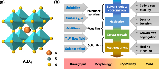
Figure 1. (a) Illustration of the unit cell of perovskite crystal with a formula of ABX3; (b) illustration of the major steps to form organic–inorganic hybrid perovskites, together with their influencing factors.
Download figure:
Standard image High-resolution imageHowever, understanding the perovskite formation process can be quite complicated due to its diversity in phase formation routes and compositions [3, 4]. So far, perovskites with mixed ions have been widely employed in this field for the pursuit of higher power conversion efficiencies (PCEs) and superior stabilities. For most studied ABX3 perovskites, the A site can be an organic or inorganic cation, such as methylammonium (CH3NH3
+, MA+), formamidinium (CH(NH2)2
+, FA+) or cesium (Cs+), the B site is a metal cation (Pb2+ or Sn2+) and the X site is dominated by halide anions (Cl−, Br− or I−) [8]. The solution synthetic methods for perovskite film include one-step and two-step deposition methods, by which all these components are assembled in an ordered network structure during fabrication. The [BX6]4− octahedra made up by a central metal cation (B2+) and halogen anions (X−) adopt corner sharing connections to form tetragonal or cubic network structures with the sizes of B- and X-site ions following the octahedral factor limit (0.44 ⩽ rB/rX ⩽ 0.90). The hollows of the network are filled and stabilized by A-site cations with their size following the Goldschmidt tolerance factor limit (0.80 ⩽![${\text{ }}\left( {{r_{\text{A}}} + {r_{\text{X}}}} \right)/\sqrt 2 \left[ {\left( {{r_{\text{B}}} + {r_{\text{X}}}} \right)} \right]$](https://content.cld.iop.org/journals/0022-3727/54/16/163001/revision4/dabd728ieqn1.gif) ⩽ 1.0) [9–11]. All the changes in composition and parameters of the unit cell deliver varied formation energies, leading to diverse perovskite formation processes.
⩽ 1.0) [9–11]. All the changes in composition and parameters of the unit cell deliver varied formation energies, leading to diverse perovskite formation processes.
Despite the complexities mentioned above, deepening our knowledge of the formation process of perovskite films is necessary because there are close correlations between film qualities and device working stabilities. For example, methods to increase the average grain size can lead to reduced density of grain boundaries (GBs), which then benefits perovskites in many aspects, including lower trends of moisture diffusion rate [12], increased activation energy of mobile ions [13–15], suppressed photo-induced phase separation [16], and improved oxygen stability [17, 18]. On the other hand, methods to form grains on the nanometer scale benefit inorganic PSCs with enhanced phase stabilities [19, 20]. Tuning the crystallization kinetics [21–25] or phase formation path [26–29] to form compact and uniform perovskite films helps to decrease the point defects or active impurities [30] located in the GBs or voids. These imperfections in crystal usually initialize the decomposition of perovskites, especially when there is significant defect/impurity migration and accumulation around charge-collecting interfaces [31, 32]. Besides, increasing the interaction between perovskites and substrates [33, 34], or slowing down the crystallization of perovskites in mesoporous structures [35], can lead to high crystallinity at the bottom side of perovskite films and improved interfacial electrical contacts, which prevent devices from high interfacial trap densities and interface-related degradations. For these reasons, insights into the nucleation and crystal growth of perovskites are always important.
The perovskites can crystallize rapidly due to their exothermic reaction (e.g. −0.1 eV for MAPbI3 [26, 36]) and low activation energy (e.g. 0.70 ~ 1.0 eV for MAPbI3 [37, 38]), which on the other hand brings difficulties into their morphology control. As a consequence, many strategies have been developed for better control of the film formation processes. From a crystal formation environment points of view, the fabrications of perovskite films experience three stages including precursor solution (figure 1(b)), wet thin film and solid-state film, all of which offer unique physical and chemical conditions. Taking the most commonly used MAPbI3 as an example, the formation of perovskite phase is initialized by PbI2-based complexes (such as PbI3 −, PbI4 2−) coordinating with organic solvents (such as N,N-dimethylformamide (DMF), dimethyl sulfoxide (DMSO)), which generate colloid particles in solution; and then the nucleation and growth of perovskite occurs in either liquid or solid phase (converted from preformed solvated phase), which is quite sensitive to the used fabrication procedures, largely determining the basic morphology and crystallinity of the obtained polycrystalline films. Finally, the obtained film is post-treated for further improved morphology and crystallinity. Developing methods to improve the film crystallinity, morphology, fabrication throughput and yield are the key targets for the commercialization of PSCs. However, these targets may contradict each other in general. Deep insights related to the nucleation and crystal growth processes are hence crucial to circumvent these contradictions. In recent years, there have been some excellent reviews on the fabrication of organic lead halide PSCs [3, 39–47]. Considering there were increasing advances published recently, this review is devoted to giving a timely update on the recent advances together with some discussions on the relevant mechanisms behind the nucleation and crystallization processes.
In this review, a close look into the formation process of perovskites from precursor solution thinning to thin film post-treatment is provided. It is organized by discussing the following major questions: how nuclei formed from the precursor solution; how to control the density and location of nucleation; which factors influence the crystal growth; how to control the uniformity of large-scale perovskite films; what roles the substrate plays in perovskite nucleation and growth; and finally, how post-treatments improve the crystallinity and morphology.
2. Colloids and intermediate phase
The colloidal nature of perovskite precursor solutions plays a crucial role in the nucleation and growth of perovskite [48, 49]. The colloids in perovskite precursor solution are suggested to be made of a soft coordination complex in the form of a lead polyhalide framework between organic and inorganic components and can be structurally tuned by the coordination degree [49]. As displayed in the absorption spectra of PbI2 solution in DMF with increasing concentration of MAI (figure 2(a)), the formation of plumbate complexes of PbI3 − and PbI4 2− was evidenced by absorption peaks at 370 and 425 nm, respectively [48, 50]. The sizes of the colloids can be evaluated by dynamic light scattering (figure 2(b)) [49], based on which some characterizations were noticed: first, the sizes of the colloids can vary in a broad region from a few nanometers to micrometers; second, many factors can influence the distribution of colloid size, such as the concentration of raw materials, the organic/inorganic component ratios [51], introduced additives [51–54], the aging time of the solution [55, 56] and the acid–base equilibrium [57]. For example, adding formic acid (HCOOH) changed the acid–base equilibrium in MAPbX3 in γ-butyrolactone (GBL)/DMF/DMSO precursor solutions, which resulted in an increased quantity of colloid particles due to the dissociation of bulky colloids under the increased concentration of H+ ions [57]. Generally, a precursor solution with reduced colloid size is favored as it facilitates the crystallization of perovskites.
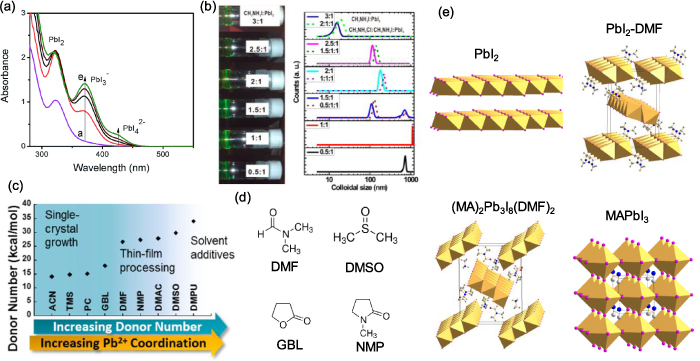
Figure 2. (a) Absorption spectra of 250 mM PbI2 solution in DMF with increasing concentration of MAI, showing the increasing concentration of plumbate complexes. (b) Colloidal properties of perovskite precursors at room temperature evidenced by the Tyndall effect and dynamic light scattering results. (c) Gutmann donor number (DN) of different solvents showing the relation with Pb2+ coordination and preference for the function for perovskite crystal growth. (d) Molecular structure of common applied solvents: N,N-dimethylformamide (DMF), dimethyl sulfoxide (DMSO), γ-butyrolactone (GBL) and N-methyl-2-pyrrolidone (NMP). (e) Crystal structures of PbI2, PbI2–DMF solvated phase, (MA)2Pb3I8(DMF)2 solvated phase, and MAPbI3 perovskite. (a) Reprinted from [48] with permission of The Royal Society of Chemistry. (b) Reprinted with permission from [49]. Copyright (2015) American Chemical Society. (c) Reprinted with permission from [58]. Copyright (2018) American Chemical Society.
Download figure:
Standard image High-resolution imageSince a Lewis acidic Pb2+ center can be coordinated by a Lewis base from six directions, there is competition between I− ions and the organic solvent over their coordination with Pb2+, depending on their binding strength. The coordinating ability of a solvent can be described by its Gutmann donor number (DN) as shown in figures 2(c) and (d). According to Hamill et al's results, the Pb–solvent coordination becomes significant when DN exceeds 18.0 kcal mol−1 [58]. In these situations, solvated phases form in solution prior to the perovskite phase. For the commonly involved solvents, the crystal structures of PbI2–solvent and MAI–PbI2–solvent (e.g. DMF, DMSO) were revealed as shown in figure 2(e) [59–62]. These solvated phases contain 1D edge-sharing PbI6 octahedral chains, separated by solvent molecules through Pb–O interactions. This crystal generally forms a 1D fibrous structure because it grows fast along its [100] direction [59].
The stability of these solvated phases increases with the donor number of the solvent. For example, for DMF with DN = 26.6 kcal mol−1, the PbI2–DMF-based solvated phase (defined as PDS, e.g. PbI2–DMF phase or MA2Pb3I8(DMF)2) mainly forms in the wet film during the drying process and partial loss of these solvated phases in the DMF molecules with the evaporation of the solvent. This temporary solvated phase can be detected by in situ grazing incidence wide angle x-ray scattering (GIWAXS) characterizations [64, 65]. For DMSO with DN = 29.8 kcal mol−1, its PbI2–DMSO-based solvated phase (e.g. MA2Pb3I8(DMSO)2) was reported to be stable up to a temperature of ~85 °C, which was different to that of PDS and meant the PbI2–DMSO-based solvated phase remained in the solid-state films after the drying process until being heated [66]. For GBL with DN = 18.0 kcal mol−1, the binding of GBL on Pb2+ is relatively weaker, which makes it suitable for growing perovskite single crystal in liquid phase without forming a competitive solvated phase [67].
Understanding the colloidal nature and the presence of solvated phase is important since it impacts on the formation of perovskite in the following ways: (a) determines the nucleation of perovskites; (b) retards the crystallization process of perovskites; and (c) influences the defect density of the resulted film.
First, the PbI2-based solvated phase precipitated firstly from solution during solvent evaporation, the amount of which can be either pronounced or hard to detect, depending on the stability of this phase (binding strength) and the solubility discrepancy between PbI2 and other components (e.g. AX salt) [68]. In 3D perovskites spin-coated by one-step method, dissolving stoichiometric molar ratios of PbI2 and MAI in DMF or DMSO always resulted in discontinuous perovskite films consisting of many needle-like crystals [49, 69]. In order to form compact perovskite film, much more additional MAI salt is required in the precursor solution. The reason for this molar-ratio-induced morphology change is actually caused by the over-sized solvated phase, which does not form compact films with its 1D crystal shape. Adding additional MAI helps to suppress the formation of oversized solvated phase [69]. For doctor-bladed perovskite films fabricated with insufficient solvent removal rate, significant solvated phase remained in the solid-state films, leading to poor PCE output. A high blading temperature of over 100 °C was reported to suppress the formation of solvated phase and significantly increase the PCE [64]. When poly(methyl methacrylate) (PMMA) was added into the precursor solution, the carbonyl groups in PMMA formed an intermediate adduct with PbI2, by which PMMA acted as the template for the nucleation of the solvated phase. By adjusting the amount of PMMA (figure 3(a)), the nucleation was controlled and the grain size and orientation of the resulting perovskite were modified [70]. Moreover, in a recent work, the precipitation of PbI2-based solvated phase was highlighted to play the dominant role in the formation of quasi-2D perovskites. For quasi-2D perovskite cast from DMF solvent, its PDS phase was found to be always formed prior to perovskite and its surface was converted to 3D-like perovskite during the solvent evaporation, which acted as the most favorable nucleation site for the templated growth of 2D perovskites [68]. The location and density of the preformed PDS essentially determined the morphology evolution and orientation of the resulted quasi-2D perovskites, as shown in figures 3(b) and (c).

Figure 3. (a) Top scanning electron microscopy (SEM) of perovskite films deposited by the polymer-templated nucleation and growth method with different concentrations (mg ml−1) of PMMA before annealing (left column) and after annealing (right column). (b), (c) Illustration of templated growth of oriented 2D perovskites on 3D-like perovskites, where the PbI2–DMF-based solvated phases (PDS) preformed on the surface of the precursor solution and converted to 3D-like perovskites resulting in the vertically oriented growth of 2D perovskites. (d) Schematics showing the formation of the perovskite layer with and without urea. (e) Perovskite films without (upper) and with urea (lower) as a function of heat-treatment temperature and time. (f) X-ray diffraction patterns of solvated phase films fabricated in ambient air and in a glove box with sample spinning times of 20 s, 2 min and 10 min. (a) Reprinted by permission from Springer Nature Customer Service Centre GmbH: [Springer Nature] [Nature Energy] [70] (2016). (b), (c) Reprinted by permission from Springer Nature Customer Service Centre GmbH: [Springer Nature] [Natue Communications] [68] (2020). (d), (e) Reprinted from [71], Copyright (2017), with permission from Elsevier. (f) Reprinted by permission from Springer Nature Customer Service Centre GmbH: [Springer Nature] [Nature Communications] [72] (2020).
Download figure:
Standard image High-resolution imageSecond, for the purpose of retarding the crystallization process of 3D perovskite, a solvent with high DN such as DMSO or N-methyl-2-pyrrolidone (NMP) was often introduced into the precursor solution to form a stable solvated phase, which converted to perovskite at a slower speed. Due to the weak interaction between formamidine iodine (FAI) and DMSO, for FA-based 3D perovskites, NMP and thiourea were added into the perovskite precursor solution instead and stable solvated-phase films were obtained after dripping of antisolvent solution, which resulted in compact and uniform perovskite films after annealing [23, 73]. Reversely, by applying volatile noncoordinating solvents (acetonitrile (ACN) and 2-methoxyethanol (2-ME)), fast and high-density nucleation of perovskite can be achieved, which enables a speed of 99 mm s−1 for blade coating at room temperature [74]. Revealed by the Fourier-transform infrared spectroscopy spectra, some additives with electron pair donors form solvated phase with PbI2. Due to the non-volatile nature of additives (urea for example, non-volatile at temperature <130 °C), the remained additives during the annealing process retard the growth of perovskite and serve as defect passivators at the perovskite GBs, as shown in figures 3(d) and (e) [71]. As another example, by controlling the DMSO/DMF ratio in MAPbI3 perovskite solutions, the perovskite/MA2Pb3I8(DMSO)2 ratio of the as-spun perovskite film was controlled. It is found that the pure MA2Pb3I8(DMSO)2 film enjoyed an up-growth of perovskite, which exhibited good interface contact with the hole-transferring layer beneath [75].
Third, it has been reported that the presence of I-rich iodoplumbate complexes in precursor solution may induce defects [52, 76]. By using PbCl2 as a lead source, the amount of PbI4 2− in precursor solution was reduced, resulting in suppressed charge recombination centers in perovskite film [76]. As another example, adding methylamine molecules was reported to effectively reduce the colloid size of polyiodide complexes in the precursor solution and eliminate the formation of oxidized I2, leading to perovskite films with reduced defect density by one order. This is because the additional MA acts as a Lewis base to coordinate with Pb2+ ions, which split the bulky I-rich iodoplumbate complexes into smaller pieces by its steric effect, resulting in suppressed formation of I2 in the precursor solution and related defects in the perovskite films [52].
Understanding the formation of solvated phase is key to clarifying the role of H2O molecules in the formation of perovskites, about which there have been controversial explanations [77, 78]. In a recent report, it was revealed that the polar H2O molecules promote the desolvation of DMSO from solvated phase (figure 3(f)), which reduces the energy barrier for crystal growth (see related introduction below) [72] so that ambient moisture can lead to oversized 1D MA2Pb3I8(DMSO)2 fibers, hindering the formation of compact perovskite films. On the other hand, the desolvation effect of the H2O molecules helps the conversion of MA2Pb3I8(DMSO)2 solvated phase into perovskite phase. By controlling the water-assisted nucleation and growth of MA2Pb3I8(DMSO)2 with a prenucleation step, high-quality perovskite films were obtained in ambient air [72].
When a considerable quantity of Cs+ ions (e.g. >5%) were added into the precursor solution, the strong binding between Cs+ ions and PbI2-based complexes overpassed the coordination effect between Pb2+ centers and the solvent, which then caused a coexistence between the PbI2-based solvated phase and  -CsPbI3 phase [28]. The presence of
  -CsPbI3 phase gave a slower formation rate of perovskites than that of PbI2-based solvated phase, resulting in different crystallization pathways and film morphologies.
The chemical status of the precursor solution is also extremely important for the lateral fabrications as it impacts on the impurities of the raw materials and hence the stability of the precursor solution [79, 80]. Methods to monitor the evolution of the precursor solution physically and chemically are appreciated [44, 48, 49, 78, 81], which helps to reveal the underlying connections between the precursor and the defect properties of perovskite films.
3. Factors influencing the nucleation rate
3.1. Basic nucleation theory
According to classical theory, the crystallization process can be divided into nucleation and growth steps. These two processes have different sensitivities to the growing environments such as the supersaturation and air/liquid/solid interfaces, which is one of the reasons for the resulting films with very different morphology. For this reason, it is necessary to recapitulate the main points of the basic nucleation theory first.
Nuclei form when the perovskite solution becomes supersaturated, i.e. the solute concentration (C) exceeds its solubility (CS). However, these nuclei formed by thermal fluctuation are redissolved back if the supersaturation is not high enough for nucleation [41, 81–84]. The nucleation is a thermodynamic process driven by the total Gibbs free energy change (ΔG). For a homogeneous nucleation process with nuclei formed in the bulk of the solution, ΔG is the sum of the bulk free energy change (ΔGV) and surface free energy change (ΔGS):
Here, r is the radius of sphere nuclei, γ is the unit surface energy of the liquid–nuclei interface and the unit bulk free energy (ΔGB) is proportional to the logarithm of supersaturation ratio (S, defined as S = C/CS), i.e.  . Hence,
  becomes positive when the solution becomes supersaturated.
  does not necessarily turn positive with
  , but depends on whether the
  overcomes the ΔGS. Taking ΔGS as positive and ΔGV as negative, a critical nuclei radius (r*) defined by
  can be obtained, as shown in figure 4(a). If its size exceeds r*, the fluctuation-induced clusters will be thermodynamically stable and tend to grow further as nucleation centers [41, 81–84]. According to this mechanism, an energy barrier (
 ) exists at r = r* with a value defined by equation (1) (figure 4(a)), which hinders the spontaneous nucleation. The height of
 decreases when the supersaturation ratio (S) increases.
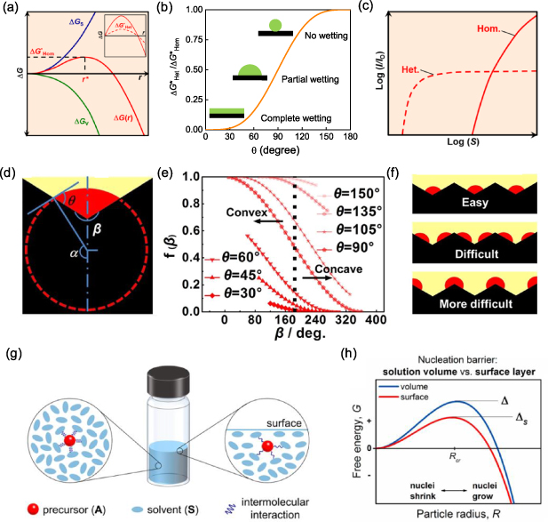
Figure 4. (a) Free energy change (ΔG), sum of surface (ΔGS) and volume (ΔGV) free energy changes, with a function of nucleus radius (r) for homogeneous nucleation (inset: heterogeneous nucleation). (b) Relationship between the energy barrier for heterogeneous nucleation and contact angle depending on the wettability of the foreign surface. (c) Normalized nucleation rate as a function of supersaturation ratio (S) for homogeneous and heterogeneous nucleation. (d) Model of nucleation on a single concavo-convex substrate. (e) Correlation between the energy barrier and contact angle. (f) Sequence of nucleation sites on the rough substrate. (a), (c) Reprinted with permission from [3]. Copyright (2019) American Chemical Society. (d)–(f) Reprinted by permission from Springer Nature Customer Service Centre GmbH: [Sprigner Nature] [Scientific Reports] [85] (2017). (g), (h) Reprinted with permission from [86]. Copyright (2017) American Chemical Society.
Download figure:
Standard image High-resolution imageOn the other hand, the presence of both liquid/solid and air/liquid interfaces impacts on the energy barrier. In the case of heterogeneous nucleation, perovskite nucleates on liquid/solid interfaces (such as substrates or added nucleation centers) with its ΔGS part reduced due to the presence of foreign surfaces. As a consequence, heterogeneous nucleation becomes easier than homogeneous nucleation with its energy barrier ( ) reduced:
where θ is the contact angle, which can vary from 0° to 180°. The energy barrier for heterogeneous nucleation reduces significantly when θ decreases, depending on the wettability of the foreign surface (figure 4(b)).
For a nucleation process with an energy barrier of  , its nucleation rate (I) is given by
where  represents the nucleation energy barrier and QD represents the activation energy for the transport of solute 'monomers' to the nucleus/solution interface.
Although both homogeneous and heterogeneous nucleation may take place during the drying process, these two processes have different sensitivities to the supersaturation of the solution due to different  values, as shown in figure 4(c). In the low-S region, for an ideal solution with uniform concentration and temperature, heterogeneous nucleation is the only process due to its lower
  value than that of homogeneous nucleation (i.e. lower threshold S). Due to this characterization, the low-S region has been widely employed to form single crystal with introduced seeds [40]. When S increases (e.g. due to faster solvent removal rate or a faster cooling process), homogeneous nucleation takes place and competes with heterogeneous nucleation, as shown in figure 4(c). However, the heterogeneous nucleation rate is limited by the total area of the foreign surface. Hence, in the case of the high-S region (e.g. injecting antisolvent such as chlorobenzene (CB) or ethyl alcohol (EA)) [21, 87], the homogeneous nucleation process becomes dominant [3, 82].
Heterogeneous nucleation was thought to be less common in the fabrication of perovskites a couple of years ago [3]. However, with growing demands on the precise manipulation of perovskite crystallization, the importance of the heterogeneous nucleation mechanism has increased gradually. One example is the emerging strategies for crystallization controlling with seed-containing precursor solution [88, 89]. The external seed method offers better reproducibility in the film quality [90]. Another updated understanding is that the nucleation of perovskite phase is largely determined by the preformed PbI2-based solvated phase, which triggers heterogeneous nucleation of perovskite on its surface. Moreover, the heterogeneous nucleation of Ruddlesden-Popper (RP)- and Dion-Jacobson (DJ)-type quasi-2D perovskites on 3D-like perovskite have been demonstrated to be efficient during the drying process, which explains the conditional vertical orientation of quasi-2D perovskites [68].
For a certain foreign surface, the heterogeneous nucleation rate can be widely varied depending on its surface treatment and roughness. As the wettability of the surface is influenced by its surface energy (γ), treating the foreign surface with plasma is a feasible method to lower  and therefore promote the heterogeneous nucleation rate [86]. More generally, as modeled by Yang et al, when the introduced surface is rough, the heterogeneous nuclei prefer to form in the concave regions, as shown in figure 4(d) [85], which is attributed to the further reduced surface free energy item. Figure 4(e) plots the dependence of the energy barrier ratio (i.e.
  ) on the contact angle (θ) and the local cone angle as schematically shown in figure 4(f). Based on this consideration, the nucleation rate is not uniform on a rough surface and the formation of nuclei on sites at the concave regions is energetically favored. After nuclei preferentially form at substrates, full coverage of the substrate is prospected as the propagation of perovskite growth [85]. Therefore, the heterogeneous nucleation can be promoted by increasing the surface roughness of the substrate. To achieve rough substrates, mesoporous structure or a layer of sparsely distributed nanoparticles are applied for heterogeneous nucleation [91, 92]. However, the limited mass transportation in the rough surface emerges as an influencing factor, which sometimes leads to interfacial cavities if heterogeneous nucleation is not dominant [93].
At the air/liquid interface, the surface tension plays a role in accelerating the nucleation [86]. This is because the surface region of the liquid is under strain due to the surface tension, which causes an increased average intermolecular distance compared with the interior liquid phase (figure 4(g)). The increased average intermolecular distance weakens the binding effect between solvent and solute and hence increases the ΔGB value in equation (1), which then reduces the energy barrier for nucleation ( ) as illustrated in figure 4(h). This accelerated nucleation on the liquid surface increases with the surface tension of the used solution. This effect has been reported to grow large perovskite single crystals on the centimeter scale with the liquid surface function as the high-priority nucleation region, such as MAPbI3, MAPbBr3, MASnBr3 and 2D (PEA)2PbI4 perovskites. On the other hand, it should be mentioned that the nucleation rate at the liquid/air interface can be influenced by other factors such as concentration gradient and temperature gradient, which overpass the surface tension effect in the case of fast solvent removal [68, 74, 94, 95].
3.2. Methods to accelerate nucleation
The antisolvent method appears to be an efficient strategy to quickly improve the supersaturation of perovskite precursor solution [21, 87, 96]. While the substrate is spinning, a nonpolar antisolvent (e.g. toluene, chlorobenzene, or diethyl ether) is dripped onto the substrate (shown in figure 5(a)). It not only drives out the solvent much faster than it would evaporate by itself but also reduces the intrinsic precursor solubility in the remaining solution upon mixing of antisolvent into it, leading to rapid crystallization for uniform, ultra-smooth perovskite thin films. To date, antisolvent engineering has been widely used to fabricate PSCs with high PCE of over 22% due to its high reproducibility in nucleation control [97–100]. A similar approach to solvent engineering applies the antisolvent after film deposition [63]. As shown in figure 5(b), NMP and diethyl ether were used as the solvent and antisolvent, respectively [101]. A similar method was also adopted to prepare low-band-gap FA0.75Cs0.25Pb0.5Sn0.5I3 films through immersion in an antisolvent bath [102]. Beyond the antisolvent method, mixture solvents combining volatile noncoordinating solvents (ACN and 2-ME) and low-volatile high-coordinating solvents (DMSO) offer a strategy for fast drying in the early nucleation stage and retarded drying in the lateral growing stage. The fast drying of ACN and 2-ME formed high supersaturation in the bladed wet film and hence formed a high density of nuclei, which enabled a high speed of blading (99 mm s−1) of uniform solid films at room temperature [74]. The strong coordination between DMSO and PbI2 guaranteed the slow formation of perovskite phase in the bladed film with large perovskite grains [74]. Scanning electron microscopy (SEM) images showed that these films were still compact and uniform, but the grain size increased to 1–2 μm in the lateral directions. Moreover, promoting the volatilization of the solvent by blowing the casted wet film with N2 flow has been introduced in both spin-coating [103] and blading methods [68, 95], which lead to rapid formation of a supersaturation region located on the top of the wet thin film.
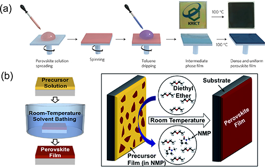
Figure 5. (a) Antisolvent engineering technique. (b) Antisolvent/solvent extraction process after film deposition. (a) Reprinted by permission from Springer Nature Customer Service Centre GmbH: [Sprigner Nature] [Nature Materials] [96] (2014). (b) Reprinted from [101] with permission of The Royal Society of Chemistry.
Download figure:
Standard image High-resolution imageIn addition to the common methods mentioned above, other analogical methods to accelerate supersaturation of the perovskite solute include gas-assisted deposition, vacuum flash-assisted solution process (VASP) and thermal annealing. Flowing Ar gas was introduced over a semi-wet film during spin-coating to speed up solvent evaporation. The promptly formed supersaturation encouraged rapid formation of more nuclei [103]. As shown in figure 6(a), the VASP method was also used to facilitate rapid supersaturation of the perovskite solute, yielding more homogeneous films with full surface coverage and without pinholes [104]. High-temperature thermal annealing could induce fast removal of the solvent to create a supersaturation environment of the perovskite precursor solute (figure 6(b)). This accelerates the perovskite nucleation [105]. After increasing the thermal annealing temperature, the crystalline grain size improved from an average of 300 nm to 1 μm.
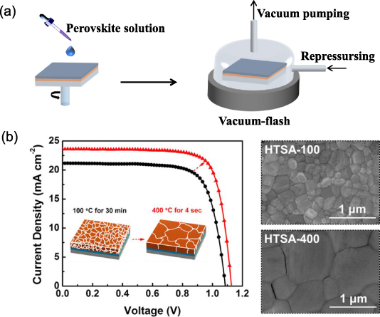
Figure 6. (a) Schematic illustration of nucleation/crystallization procedures during the formation of perovskite film via vacuum-flash assisted solution processing (VASP). (b) Device efficiency diagram and perovskite film morphology graphs by different thermal annealing temperatures for different time periods. (b) Reprinted with permission from [105]. Copyright (2017) American Chemical Society.
Download figure:
Standard image High-resolution image3.3. Methods to suppress nucleation
As the mechanisms mentioned above accelerate the nucleation rate, methods to suppress the nucleation rate are also highly desirable in many cases when large grain size is pursued. Tuning the supersaturation of solution through temperature or drying process engineering are accessible methods, but bring complexity in uniformity and yield control in large-area fabrication. To date, it is known that the stage of forming PDS in the wet film is prior to the formation of perovskite phase, which actually dominates the formation of perovskite phase at nucleation sites. Hence, manipulation of PbI2-based solvent phase has become an efficient method of nucleation rate engineering. Using organic molecules with high donor number can form a coordinate complex with PbI2-based clusters, which helps to retard the precipitation of PbI2 from solution. However, molecules with high donor number (e.g. DMSO, NMP) form a stable solvated phase with PbI2, which remains in the solid films until it is heated. Wang et al revealed that using additional AX salts (such as NH4Cl, MACl, NH4I, MAI, and MABr) in precursor solution efficiently suppressed the nucleation rate of PbI2-based solvated phase (figures 7(a) and (b)), which eliminated the needle-like crystals in resulted films and led to greatly enlarged grain sizes of 2D perovskites [68]. Among these AX salts, NH4Cl is a promising choice for iodine perovskites as it evaporated completely in the post-thermal-annealing process. This NH4Cl additive method was later applied to doctor-bladed 3D perovskites by Dai et al [106], in which the suppressed nucleation rate was in situ observed by optical microscope (figure 7(c)). The origin of the suppressed nucleation by AX salts still needs to be clarified. A possible reason is the increased charges of the PbI2-based colloid particles after binding with excessive halide ions offered by additional AX salts, which hinders the aggregation of colloid particles by an electrostatic repelling effect [48]. On the other hand, some bulky zwitterions were also reported to reduce the nucleation rate of perovskites, such as 3-(decyldimethylammonio)-propane-sulfonate inner salt (DPSI) [107] and 3-(1-pyridinio)-1-propanesulfonate (NDSB201) [108].
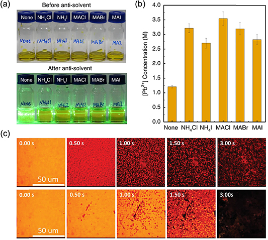
Figure 7. (a) Photos of butylamine (BA)-based RP perovskite precursor solutions (<n >= 4, 210 μl) without additive or with AX additives (AX/PbI2 = 0.5) before and after the injection of chlorobenzene. (b) Influence of the AX additives (AX/PbI2 = 0.5) on the critical concentration of precursor solution for the nucleation of PbI2–DMF solvated phase in DMF. (c) In situ microscopy observation of the drying process of the as-coated perovskite film without NH4Cl (above) and with NH4Cl (below). (a), (b) Reprinted by permission from Springer Nature Customer Service Centre GmbH: [Springer Nature] [Natue Communications] [68] (2020). (c) [106] John Wiley & Sons. [Copyright © 2020 WILEY‐VCH Verlag GmbH & Co. KGaA, Weinheim].
Download figure:
Standard image High-resolution imageMoreover, for 2D perovskites, the preferential nucleation sites located at the surface of the precursor solution and the subsequent templated growth from heterogeneous nucleation result in the desired crystal orientation, which boosts the efficiency of the resulting solar cells [68, 109]. As shown in figure 8(a), by applying solvents with high boiling point and long chain cations with higher solubility, a low supersaturation was maintained. This further guaranteed the domain heterogeneous nucleation and crystal growth beneath the preformed perovskite crust on the surface instead of homogeneous nucleation in the solution interior [109, 110].

Figure 8. (a) Illustration of the relationship between supersaturation control and crystal orientation of 2D perovskite. (b) Growth mechanism of thin CsPbI2Br film with spin-coating processing. (c) Schematic illustration of the film growth at different temperatures. (d) Schematic of the fabrication procedure of perovskite films using perovskite seeding growth. (a) Reprinted with permission from [110]. Copyright (2019) American Chemical Society. (b), (c) Reprinted from [111]. Copyright (2018), with permission from Elsevier. (d) Reprinted by permission from Springer Nature Customer Service Centre GmbH: [Sprigner Nature] [Nature Communications] [88] (2018).
Download figure:
Standard image High-resolution imageOptimizing the precursor solution temperature can also be used to adjust the nucleation density. The precursor solution temperature is closely related to solubility and solvent evaporation rate. As shown in figures 8(b) and (c), a systematic study of the correlation between crystallization and the precursor solution temperature has been conducted for solution-processed CsPbI2Br film [111]. On one hand, the nucleation step is supposed to be suppressed due to the enhanced solubility of the precursor at elevated temperatures. On the other hand, the supersaturation ratio might increase significantly due to the much faster solvent removal rate. To obtain thick film with a larger crystalline grain size, the temperature and drying procedure of the precursor solution should be carefully adjusted to avoid the formation of a high density of nuclei.
3.4. Employing foreign nucleation centers
As another strategy to manipulate the concentration of nucleation centers, external nuclei were intentionally introduced into the precursor solution. Taking advantage of the low solubility of cesium (Cs+) salts, Cs+ salts were reported to be added into PbI2 precursor in the first step of two-step methods (as shown in figure 8(d)) [88, 90, 112] or into perovskite precursor solutions for one-step methods [89]. The Cs+-enriched regions served as seeds to facilitate heterogeneous crystallization and crystal growth of the perovskites. As a result, large grain size and preferential crystallographic orientation of perovskite film were achieved, along with improved efficiency and stability of the resulting solar cells. Similarly, some additives (such as C60 [113], [6,6]-phenyl-C61-butyric acid methyl ester (PCBM) [25], 3,9-Bis(2-methylene-(3-(1,1-dicyanomethylene)-indanone))-5,5,11,11-tetrakis(4-hexylphenyl)-dithieno[2,3-d:2',3'-d']-s-indaceno[1,2-b:5,6-b']dithiophene) (ITIC) [25], 1,3-bis[3,5-di(pyridin-3-yl)phenyl]benzene (BmPyPhB) [114], V2Ox nanoparticles [115], black phosphorus quantum dots [116] and so forth [39]) were added into perovskite precursor solution or antisolvents [117–119], acting as nucleation sites. A merit of using external nuclei is their controllable nuclei concentration, which is less sensitive to the variable drying process.
3.5. Manipulation of nucleation region
Control over the nucleation location is another important route to manipulating the morphology evolution and dominating orientation of resulting perovskite films. During the drying of the wet film, the environment for nucleation is far from equilibrium conditions with imposed concentration and temperature gradient. As shown in figure 9(a) [120], with the evaporation of the solvent at the upper surface, the concentration of precursor solution decreases from the top to the bottom region. Meanwhile, the evaporation of the solvent is an endothermic process, which tends to make the temperature of the precursor solution increase from the top to the bottom region. Generally, the solubility of perovskite raw material PbI2 in a solvent (e.g. DMF, DMSO, NMP) decreases at lower temperature. Hence, the top region of the wet film with high concentration and low temperature can be the preferential location for nucleation [120]. On the other hand, as introduced above, the substrate can also become a preferential nucleation region due to the lower energy barrier of heterogeneous nucleation than that of homogeneous nucleation [120]. Since the nuclei formed in solution are very small and surrounded by solvents, it is challenging to directly characterize the nucleation region for a given material system and fabrication procedure.
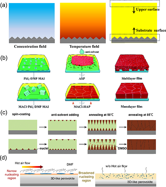
Figure 9. (a) Scheme of concentration field, temperature field and the possible preferential nucleation locations in the precursor solution film during evaporation. (b) Scheme of the formation of the multilayer and monolithic MAPbI3 films by the anti-solvent method and heat-assisted method. (c) Illustration of the nucleation and growth of the grains for the films fabricated using room-temperature (up) and frozen (down) substrates. (d) Illustration of the hot-air-flow-induced narrow 3D-like perovskite formation region on the liquid surface and the slow-evaporation (w/o hot air flow)-induced 3D-like perovskite dispersion in a broadened region inside the 2D perovskite precursor solution. (b) Reprinted from [121] with permission of The Royal Society of Chemistry. (c) Reprinted from [94] with permission of The Royal Society of Chemistry. (d) Reprinted by permission from Springer Nature Customer Service Centre GmbH: [Springer Nature] [Natue Communications] [68] (2020).
Download figure:
Standard image High-resolution imageThe nucleation location can be engineered through controlling the local concentration and temperature with designed deposition methods. In the antisolvent method, the dripping of antisolvent extracts the solvent from the precursor solution in an extremely short time, which is supposed to induce fast nucleation at the upper part of the precursor solution [121, 122]. Unsatisfactorily, it was proposed that the compact perovskite film formed on the upper surface may hinder the penetration of the antisolvent, resulting in the formation of shrinkage voids at the bottom layer (figure 9(b)). A method combining MACl additive and substrate heating was reported by Li et al to tune the nucleation location. The MACl additive was used to retard crystallization and the substrate heating was used to increase nucleation rate. This led the perovskite or solvated phase to form at the bottom substrate, which eventually resulted in growing a compact monolithic MAPbI3 film with an average grain size of 3.6 µm [121]. In another attempt, frozen substrates were employed to increase the supersaturation around the substrate through the antisolvent method; the crystals nucleated both at top and bottom regions of the wet thin film during the antisolvent method, as shown in figure 9(c) [94].
For the doctor-blading method, the volatilization of DMF solvent at room temperature is much slower than that in the spin-coating method. For this reason, the temperature gradient and concentration gradient along the vertical direction are significantly counteracted by heat transfer and mass transport, and therefore the surface of the solution is not necessarily the dominant nucleation region. As a consequence, methods of controlling the nucleation and crystallization in spin coating have become invalid in doctor blading. For example, in a case of dealing with quasi-2D perovskite, nucleation on top of the solution was intentionally pursued by hot air blowing, which accelerated DMF volatilization on the precursor solution surface, as shown in figure 9(d). The preferred nucleation on top of the solution triggered a downward growth of BA2MA3Pb4I13 perovskite with out-of-plane orientation, which was unavailable for the same devices fabricated without hot air flow due to the possible homogeneous nucleation in the bulk of the solution [68].
On the other hand, when the drying process of doctor-bladed wet thin film is slow, the insufficient supersaturation does not offer uniformly distributed nucleation centers. In this case, the lateral liquid flow driven by the temperature gradient and concentration gradient along the horizontal direction mediates the shape of the liquid phase and the location of its drying fronts. The nucleation may start at the edge of the precursor solution because the drying at the edge of the solution film is relatively faster than that on the surface of the solution film [123, 124]. When the solution edge is not pinned by the solidified perovskite phase, the nucleation region hops with the shrinking of the solution edge, which evenly results in perovskite film featuring many concentric rings from the edge to the center of the domain [125].
4. Factors influencing crystal growth process
4.1. Basic crystal growth theory
Crystal growth occurs immediately after the formation of stable nuclei (figure 10(a)). The growth of crystal is neither a uniform nor steady process, depending on the size of the crystal and the local supersaturation. There are many mechanisms involved in the crystal growth that make the analysis quite complex. For a perovskite precursor solution with multiple components, ionic and hydrogen bond interactions, the complexity is increased further.
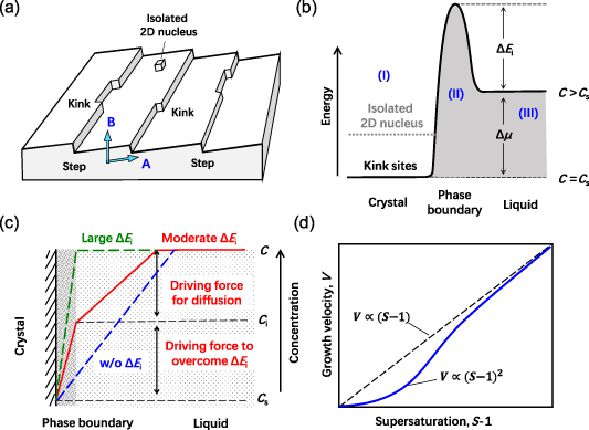
Figure 10. (a) Illustration of a crystal facet with steps, kinks and isolated 2D nucleus on its surface, where direction A is the preferred growth direction determined by anisotropic surface binding strength and direction B is the practical growth resulting from the influence of external factors. (b) Illustration of the energy changes for a building monomer incorporated into the crystal surface from a supersaturated solution, in which the energy barrier for this incorporation process at the phase boundary is also schematically shown. (c) Comparison of the solute concentration changes around the crystal surface in the case of surface-reaction-limited growth (green), solute-diffusion-limited growth (blue) and a combination of these two mechanisms (red); the proposed phase boundary region on the crystal surface region that hinders the attachment of the monomer is also schematically shown. (d) Illustration of the typical relationship between the crystal growth velocity and the supersaturation of the solution (blue), where the departure of the blue curve from the ideal linear relationship (dash) can be explained by the Burton–Cabrera–Frank (BCF) model.
Download figure:
Standard image High-resolution imageFor a simple description, the change in energy of a dispersed monomer in solution during crystallization can be schematically shown in figure 10(b) [126, 127]. The lowest energy state at the left side (region-I) represents a building monomer incorporated into the crystal surface, usually with the kinks on the surface of the crystal as the most favored sites (figure 10(a)). The isolated nucleation on the compact surface is more difficult (i.e. the 2D nucleus in figures 10(a) and (b)). The line at the right side (region-III) is determined by the average energy of a monomer dispersed in solution. The energy difference for a monomer between liquid and crystal phases is equal to the chemical potential change for crystal and liquid with the same temperature and pressure, defined as  . There is an energy barrier at the phase boundary with a height of
  , which limits the kinetic coefficient of the growing process. The presence of the energy barrier leads to a crystal growth velocity (V) defined as:
where K is the kinetic coefficient. Based on this simplified picture, the crystal growth rate is supposed to be linear with the driving force of  ; see the green line in figure 10(c). It should be mentioned that the equilibrium concentration (CS) is dependent on the facet of the crystal. For a building monomer incorporated into different facets,
  is different due to the varied binding strength of the monomer on different facets, despite the same average energy of a monomer in solution. Hence, the driving force for crystal growth is anisotropic. The
  generally reaches its highest value for the facet with the shortest interplanar distance. This is the reason that most of the quasi-2D perovskite grows fast on its (100) or (001) planes but much slower on its (010) planes [7, 128–130]. It should be clarified that, as illustrated in figure 10(a), the growth of the crystal is also determined by the mass transport (induced by
  ) and heat transport (induced by
  ) in solution. Hence, its practical growth direction (direction B) can be different from its preferred growth direction (direction A), which results in steps on the grain surface, as frequently observed in lead halide perovskite grains [131].
The energy barrier in the phase boundary regulates the crystal growth rate, which can have different natures in different mechanisms. Generally, it can be the energy required for: (a) a surface chemical reaction, (b) the monomer to break bonds with coordinating solvent molecules for its incorporation (called desolvation), or (c) the monomer to overcome steric effect and occupy a correct orientation. Taking  into consideration helps one to understand the growth of perovskite crystal. As mentioned above, in the work carried out by Zhang et al, the growth speed of PbI2-based solvated phase was reported to increase in the presence of moisture, which was explained as the reduced energy barrier for the desolvation of DMSO from PbI2–DMSO solvated phase with the assistance of H2O molecules [72]. In another work carried out by Cui et al, the Rb+ ions added to perovskite precursor solution preferred to accumulate at the phase boundary region and introduced an additional energy barrier for the incorporation of MA+ cations [132]. Similarly, the energy barrier can be increased by using Lewis-based additives [52, 133]. Increasing
  also exists in the formation of perovskite film from solid-state films dominated by a Lewis acid–base adduct, as will be introduced below.
In a special case, when the energy barrier  is ignorable, the growth of the crystal is found to be limited by the diffusion of monomers from the solution to the crystal surface with a diffusion coefficient of D. In this situation, the flux of the solute is driven by the concentration gradient between the crystal surface and the bulk of the solution (blue line in figure 10(c)). In the case of diffusion-limited growth, the growth rate is linear with the supersaturation (S − 1) of the solution. However, in most cases,
  is not ignorable in the solution because the energy barrier for desolvation is comparable with the equivalent activation energy (Ed) for the monomer to diffuse in solution (i.e.
  ). In this case, the driving force
  is shared by the diffusion process and the
  overcoming process (see the red line in figure 10(c)) with the C in equation (4) replaced by the concentration around the phase boundary region (Ci
).
overcoming process (see the red line in figure 10(c)) with the C in equation (4) replaced by the concentration around the phase boundary region (Ci
).
In both diffusion-limited growth and surface-reaction-limited growth, the growth rate (or velocity) is supposed to be linear with the supersaturation of solution (i.e. the dashed line shown in figure 10(d)). However, in the case of surface-reaction-limited growth, the growth rate departs from this rule in the low-S region with a modulated relationship of  (figure 10(d)). According to the BCF model, this departure mainly originates from the difficulty of forming an isolated 2D nucleus in a kink-free crystal surface when the supersaturation is low [127].
4.2. Evolution between nucleation and crystal growth
Precisely controlling the crystal growth speed is always desirable for the formation of high-quality, low-defect-density crystals. Tuning the supersaturation ratio of the wet film via the solvent removal rate and temperature are two feasible ways to adjust the crystal growth rate. However, these methods also induce broad impacts on the nucleation, mass transport and heat transport processes in the solution. The crystal growth itself competes with the nucleation process by influencing the mass transport and heat transport. The LaMer mechanism (also known as the self-seeding crystal growth mechanism) provides a straightforward frame to clarify the relationship between these two processes.
As shown in figure 11(a), there are three different stages in the LaMer diagram [3, 41, 84, 134–136]: (I) pre-nucleation; (II) burst nucleation; (III) growth by diffusion. At stage I, with the evaporation of the solvent, the concentration of the solution increases up to the solubility limit (CS). Further evaporation of the solvent makes the solution supersaturated but no nucleation occurs until the concentration of the solution reaches the minimum supersaturation limit ( ). At stage II, nucleation begins to precipitate when the concentration is larger than
  , which is in accordance with equation (1) and figure 11(a) where the nucleation energy barrier is surpassed and the nuclei size is larger than the critical radius r*. The formed nuclei grow with the continuous supply of solute by diffusion (i.e. named as self-seeding crystal growth), and new nuclei simultaneously precipitate. As the crystal nucleation and growth proceed, the solute is continuously consumed, which in turn suppresses the nucleation rate. At stage III, since the present crystal radius is larger than the critical radius r* and the solution is still supersaturated but below the critical concentration for nucleation (
 > C> CS), only crystal growth occurs. This mechanism can further verify the phenomenon observed in figure 8(d). When the nucleation site is introduced, the supersaturation of the system decreases and the nucleation density is lowered, which further increases the grain size. The LaMer mechanism indicates that the solution supersaturation is the primary factor in regulating the perovskite nucleation and growth and film morphology [84].
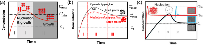
Figure 11. (a) LaMer diagrams for homogeneous nucleation. CS,  and
and  represent the solution solubility limit, and the minimum and maximum supersaturation concentrations, respectively. (b) LaMer diagrams for the perovskite nucleation and crystal growth by gas quenching with high (black line) and mediate (red line) velocity flow rate. (c) LaMer diagrams for the perovskite nucleation and crystal growth by nitrogen blowing in solution state (red line), in solvated phase (blue line) and by natural drying (black line). (b) Reprinted by permission from Springer Nature Customer Service Centre GmbH: [Sprigner Nature] [Science China Materials] [137] (2017). (c) [138] John Wiley & Sons. [Copyright © 2019 WILEY‐VCH Verlag GmbH & Co. KGaA, Weinheim].
Download figure:
Standard image High-resolution imageTo control the reaching time of supersaturation, antisolvent [21, 87, 96], gas quenching methods [21, 103], low atmospheric pressure [104, 139], hot casting [56, 140] and flash infrared annealing [141] were applied to remove the solvent quickly. In order to control the duration time of supersaturation, additives were applied by changing the solubility of the solute [68, 142] and the colloid size [43], where  may be enhanced. Figure 11(b) presents the LaMer diagram changed by the gas quenching method with varied gas flow rates. When high-velocity gas flow was applied, the solvent evaporation was accelerated, which shortened the time to reach supersaturation and resulted in a high density of nucleation sites. The resulting film was compact but consisted of grains with extra-small crystal sizes. In contrast, with a mediate-velocity gas flow, the nucleation density is relatively smaller and the resulting crystals are larger in size [84, 137]. Therefore, the window period of the second stage of the LaMer mechanism can be adjusted by controlling the dynamic process of liquid film drying, largely determining the final film morphology. As another example of gas quenching, figure 11(c) presents the effect of the starting time of air-knife assisted nitrogen blowing on nucleation and crystal growth of perovskite via a meniscus-coating method [138]. When nitrogen blowing started before the natural nucleation process, fast supersaturation resulted in a high density of nuclei and compact perovskite films (shown as a red line). However, when nitrogen blowing started after the natural nucleation process, the system reached another supersaturation state leading to a new nucleation process, which resulted in the formation of small grains accompanying the preformed large domains (shown as a blue line). The time window for applying nitrogen blowing was evaluated by in situ measurement of absorption spectra [138]. For a similar reason, the dripping time of the antisolvent is also crucial and it requires careful refinement of processing parameters in order to yield high performance [143].
4.3. Retarded growth for high-quality perovskite crystals
Generally, slow crystal growth is essential in the formation of high-quality perovskite. Retarded crystal growth of perovskite in solution has been widely reported [144–147]. A commonly used strategy is the incorporation of additives into precursor solutions. Most additives, such as 1,8-diiodooctane (DIO), hydroiodic, and hydrobromic, can form chelation with Pb2+ [8, 55, 148]. Figure 12(a) exhibits the schematic diagram for the transient chelation of Pb2+ with DIO [148]. The temporary coplanar chelation of Pb2+ with DIO as Cl− ligands happened, resulting in improved solubility of PbCl2, as shown in figure 12(b). In addition to these usual additives, the growth speeds of quasi-2D PEA2MAn −1Pbn I3n+1 (n = 3, 4, 5) perovskite were gradually reduced by adding increasing amounts of Rb+ ions into the precursor solution [132]. As shown in figure 12(c), the added Rb+ ions prefer to accumulate at the crystal growth front and form a Rb+-ion-rich region, which functions as a mild crystal growth inhibitor to retard the diffusion of organic cations at the growth front and hence regulates the crystal growth rate. This retarded crystal growth speed does not necessarily influence the average grain size, but offered an improved crystallinity characterized as narrowed XRD diffraction peaks (full width at half maximum (FWHM) reduced from 0.24° to 0.18°) and prolonged carrier recombination lifetimes (from 235 ns to 500 ns). Similarly, the retarded crystal growth of 3D perovskite in solution has been reported by using Lewis-based additives, which process the binding effect with PbI2-based complexes or organic cations, such as MA molecules [52] and N-doped graphene [133].
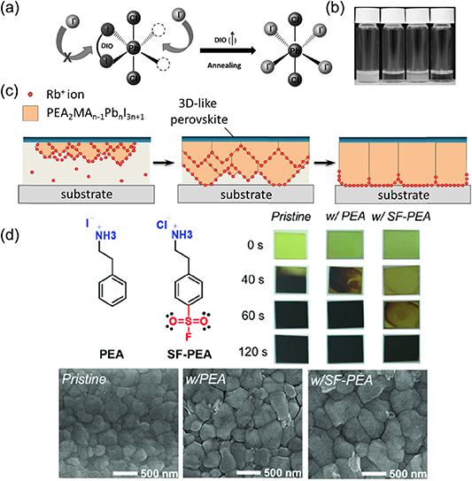
Figure 12. (a) Schematic diagram for the transient chelation of Pb2+ with DIO. (b) Solubility of the PbCl2 and PbI2 in DMF with or without additives. From left to right, PbCl2 in DMF, PbCl2 in DMF/DIO, PbI2 in DMF, and PbI2 in DMF/DIO. (c) Schematic illustration for retarded crystal growth by adding Rb+ ions into precursor solution as a crystal growth inhibitor. (d) Bulky cations (PEA and SF-PEA) modulating FAPbI3 crystallization. (a), (b) [148] John Wiley & Sons. [Copyright © 2014 WILEY‐VCH Verlag GmbH & Co. KGaA, Weinheim]. (d) [149] John Wiley & Sons. [Copyright © 2020 WILEY‐VCH Verlag GmbH & Co. KGaA, Weinheim].
Download figure:
Standard image High-resolution imageOn the other hand, retarded crystallization is also available in the formation of perovskite film from solid-state films dominated by Lewis acid-base adducts. Lewis-base molecules containing S, N and O atoms with lone pair electrons can form adducts with PbX2, which further modulate the perovskite nucleation and crystallization. Recently, a sulfonyl fluoride-functionalized phenethylammonium salt (SF-PEA) was used to form Lewis acid-base adducts with PbI2 in the precursor. This further slowed down the crystallization of FAPbI3 during thermal annealing, leading to increasing crystal size (shown in figure 12(d)). As a result, the average grain size for the pristine, w/PEA, and w/SF-PEA samples were calculated to be 315, 444, and 704 nm, respectively, indicating the increasing crystal size by the introduction of bulky cations. The interaction between Lewis acid-base adducts can be enhanced by molecule tailoring. Xu et al compared a group of S-atom contained Lewis bases with different densities of electron clouds located on S atoms, which offered gradually increased S–Pb interaction. In that study, the best-performing 4-PT additive did not enter the lattice but was attached onto the grain surface by S–Pb interaction, which significantly retarded the crystallization process and promoted high-quality black-phase CsPbI3 formation [22].
As discussed in section 2, the presence of solvated phase is important for the purpose of retarding the crystallization process of 3D perovskite. The solvent phase is actually formed by the interaction between the Lewis-base solvent and weak Lewis acid PbX2. The reported Lewis-base solvents used to retard the crystal growth are shown in figure 13(a) [23]. Among them, DMSO has been extensively employed [66, 73, 150, 151]. Due to the stronger Lewis basicity of DMSO compared to other solvents, a solvated phase of PbI2–DMSO-MAI was formed before the conversion of perovskite precursors to perovskite crystalline structures [66]. As shown in figure 13(b), the addition of DMSO was able to highly regulate the film morphology by retarding the crystal growth, which thus resulted in high-quality pinhole-free perovskite films.
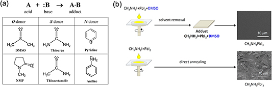
Figure 13. (a) Lewis acid (A)–base (B) reaction to form adducts (A·B) with a dative bond. Lewis bases with oxygen donor (O-donor), sulfur donor (S-donor), and nitrogen donor (N-donor). (b) Schematic representation of the fabrication procedure and plane-view scanning electron microscopy (SEM) images for the MAPbI3 perovskite layers obtained by direct one-step spin-coating of the DMF solution (a) with and (b) without DMSO. (a) Reprinted with permission from [23]. Copyright (2016) American Chemical Society. (b) Reprinted with permission from [66]. Copyright (2015) American Chemical Society.
Download figure:
Standard image High-resolution image4.4. Growth for perovskite single crystals
Single crystals of perovskites have shown remarkably low trap density and excellent charge transport properties; however, the growth of such high-quality semiconductors is a time-consuming process [67, 152]. Herein, some methods were used to accelerate the growth speed in single crystal growth. A top-seeded solution growth method was developed by Dong et al to prepare single-crystalline perovskite on a piece of silicon substrate. In this process, smaller perovskite crystals synthesized in advance separately were used as the seed to grow into larger single crystals [153]. Bakr et al reported an antisolvent vapor-assisted crystallization approach to create sizable crack-free MAPbI3 and MAPbBr3 single crystals [154]. Liu's group reported the growth of high quality single-crystal MAPbX3 (X = Cl, Br, I) by using an inverse temperature crystallization method [67, 152]. In addition to the 3D single crystals, the researchers from the same group also developed 2D perovskite single crystals [155]. As shown in figure 14, large 2D (PEA)2PbI4 perovskite single crystals were prepared using a surface-tension-controlled crystallization method. Due to the net force of the surface tension and the buoyant force, the small single crystallite could be held on the solution surface for a period of time until it grew large enough to overcome the upward force to sink to the bottom of the solution. A step-by-step cooling procedure was designed to grow (PEA)2PbI4 perovskite single crystals. Using this technique, some inch-sized 2D (PEA)2PbI4 single crystals were obtained, with the largest one reaching 36 mm in length, resulting in extraordinary device performance.

Figure 14. (a) Schematic of the surface-tension-controlled crystallization process. (b) Photographs of the (PEA)2PbI4 PSCs grown at different temperatures. (c) Corresponding photographs of (PEA)2PbI4 perovskite single crystals completed at different temperatures. (a)–(c) Reprinted with permission from [155], Copyright (2019), with permission from Elsevier.
Download figure:
Standard image High-resolution image5. Factors influencing film morphology
5.1. Basic solute transport processes
The solute dissolved in solution is redistributed during the drying process in the forms of self-diffusion and solution flows, which often impacts on the uniformity of finalized films in complex ways because it could be a combination of different flows or form complicated convective cells. Here we briefly introduce three kinds of basic liquid flow that can influence the lateral transport of the solute.
5.1.1. Capillary flow.
Capillary motion is the ability of a liquid to flow along a solid interface driven by the tendency of forming a contact line with constant contacting angle ( ; see the example in figure 15(a)) with the local tangential direction of the solid phase. This effect leads to formation of a steady, locally bent liquid surface around the suspended particle against the leveling effect induced by gravity. When two suspended particles are close, the locally bent liquid surface induced by the capillary effect, together with the liquid surface tension, forces these two particles to approach each other and finally form a minimized total area of the liquid surface, as schematically shown in figure 15(a) [124]. This mechanism hence forms attracting effects between suspended particles (solvated phase or perovskite microcrystals) and the existing polycrystalline films, leading to reduced uniformity or even pinholes in the final films.
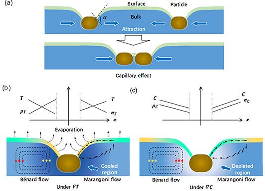
Figure 15. (a) Illustration of the capillary effect for a particle (blown) suspended on a liquid surface, where the surface and bulk of the liquid phase are marked as different colors for better clarification. The bent liquid surface results from capillary flow against gravity. (b), (c) Illustration of the Bénard flow and Marangoni flow induced by the temperature gradient (b) or concentration gradient (c), respectively. The temperature gradient is assumed by considering nonuniform surface evaporation (b), and the concentration gradient is assumed by considering significant solute depletion.
Download figure:
Standard image High-resolution image5.1.2. Bénard flow.
The Bénard flow is formed under gravity, such as in the case of a solution with local density changes ( ). The density changes can result from the expansion of liquid with heat and contraction with cold (
 ) under a temperature gradient, or the composition change (
 ) under a composition gradient, i.e.
  . Taking the suspended particle and its bent liquid surface shown in figure 13(a) as an example, when there is a cold region formed around the suspended particles due to the relatively faster surface evaporation of the solvent, a clockwise Bénard flow forms on its left side (figure 15(b), and v.v. an anticlockwise flow formation on its right side can be expected); on the other hand, when there is a solute depletion region formed around the suspended particles as the growth rate of the particle is high, the corresponding density change induces a Bénard flow with opposite direction as shown in figure 15(c). In the practical drying process, the temperature gradient and concentration gradient in solution overlap and couple with each other, making the direction of Bénard flow highly dependent on the material system and detailed drying process.
5.1.3. Marangoni flow.
The Marangoni flow is formed in the case of a solution with local surface tension change ( ) [156]. Similarly, the surface tension of a liquid is also sensitive to its temperature and meanwhile influenced by its composition with
  . Usually, the surface tension decreases with temperature with a relationship of
  , where A is a positive constant. Therefore, in the case of the temperature gradient shown in figure 15(b), the Marangoni flow on the surface region is toward the particle. On the other hand, the surface tension is also sensitive to the composition of the solution, such as the local blending ratio change in a co-solvent system due to unbalanced solvent evaporation or the concentration changes of the solute. Usually, the surface tension tends to increase with solute concentration if there are significant ionic or hydrogen bonding effects. Assuming an increased
  with solute concentration as shown in figure 15(c), the corresponding Marangoni flow would go against the particle due to solute depletion. In most cases, the Marangoni flow is most significant around the solid/liquid phase boundaries due to the presence of the capillary effect and combines with the Bénard flow to form Bénard–Marangoni convection. The Marangoni flow matters in the case of the PbI2-based solvated phase or perovskite nucleation centers that predominantly form at the liquid/air interface.
5.2. Formation of uniformity perovskite film in large-area fabrication
For fabricating perovskite films on a large scale with a lower solvent removal rate than that in spin coating, the lateral diffusion of the solute has sufficient time to occur and sometimes plays a quaint role in the nucleation and crystal growth. As shown in figure 16(a), polygonal perovskite domains filled with periodic concentric rings via a slot-die printing method were occasionally observed by different groups [125, 157], which is actually assembled by many smaller grains as verified from the cross-sectional SEM image by Deng et al. The difference in height was in the region of a few hundred nanometers. Another characterization of this observation is the clear domain centers and domain edges that can be recognized from each domain. Two mechanisms have been proposed to explain this amazing phenomenon: Deng et al assigned the round dot located in the center of each domain as the center of a convective cell (figure 16(b)), the size of the convective cell reduced gradually during the drying process and the edge of the convective cell was pinned and de-pinned repeatedly with the reduced volume of the solution, leading to a periodic self-seeding region as shown in figure 16(c) [125]. In another investigation, a periodic precipitation was proposed for explanation by Hu et al (figures 16(d) and (e)) [157]. The formation of the periodic concentric rings was a dynamic process featured as the liquid convection formed around the growth front, which led to a separated part of the solution located in front of the growth front, which finally left a new perovskite ring after dying [157]. This mechanism was sensitive to the temperature and the spacing between the blader and substrate, e.g. when the solution temperature was lower than 100 °C, many isolated perovskite islands were formed; and when the temperature was 180 °C (together with hot air blowing), the rapid self-seeding process dominated the formation process and resulted in compact film with small grains (figure 16(d)).

Figure 16. (a) Cross-section SEM images of the concentric ring structure in an as-prepared colorful organometal trihalide perovskite (OTP) film and plane-view SEM image of the as-prepared colorful OTP film. (b) Illustration of a convection cell in a thin solution film driven by the temperature difference between the heated bottom and cold top surface and the microscopy image of the as-prepared colorful OTP films prepared when the substrate temperature was 135 °C. (c) Illustration of the concentric ring structure formation from the 'coffee ring' effect as the contact line contracts through alternating pinning/depinning processes. (d) SEM images of perovskite films based on various heating temperatures. (e) Scheme of the periodic and rhythmic crystallization. (a)–(c) Reprinted from [125] with permission of The Royal Society of Chemistry. (d), (e) Reprinted by permission from Springer Nature Customer Service Centre GmbH: [Sprigner Nature] [Natue Communications] [157] (2017).
Download figure:
Standard image High-resolution imageAlthough there were different understandings of the formation of the very rough concentric rings, it is clear that the lateral solution flow and solute diffusion is undesirable for fabricating uniform, pinhole-free perovskites. Fortunately, the nonuniform problem mentioned above can be eliminated since it is quite sensitive to the removal rate of the solvent. A high-speed blading method with high film quality was successfully developed by Deng et al [158]. To give a clear understanding of film deposition mode, the perovskite film thickness as a function of blade-coating speed was measured and is shown in figure 17(a) [158]. Two distinct regimes of the film deposition mode were found. When the blading speed is below 4 mm s−1, the decrease in thickness with increasing coating speed (with a slope of −0.99) indicates the coating falls in the evaporation regime, where solution coating and crystallization occur simultaneously. When the blading speed is above 20 mm s−1, the increase in thickness with increasing coating speed (with a slope of 0.66) indicates the coating falls in the Landau–Levich regime, where crystallization occurs after the formation of wet thin film [158]. The theoretical models were proposed by Berre et al to describe the thickness dependences of the blade-coating speed (figure 17(b)) [159]. The dominant forces are different in these two modes. While surface tension dominates the fluid characteristics for meniscus coating, fluid viscosity dominates over the surface tension for fast blade coating [160]. Though the viscosity and surface tension of some precursor solutions were measured [161, 162], the relation between these two factors and perovskite crystallization and crystal growth is still not clear. Empirically, high viscosity impedes the colloid movement [163] and improves the compactness of perovskite films [164–166].
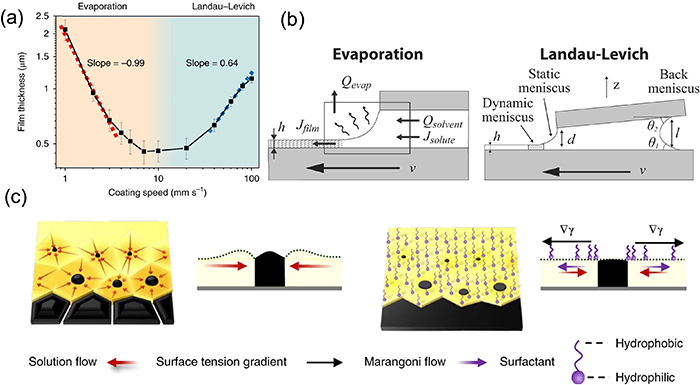
Figure 17. (a) Perovskite film thickness as a function of blade-coating speed by coating a 1 M MAPbI3/DMF solution on a 145 °C preheated substrate. (b) Schematic of the two deposition regimes. (c) Schematic illustration for the directional microscale solution flow toward perovskite islands during ink drying and the suppressed solution flow dynamics in the presence of surfactant. (a), (c) Reprinted by permission from Springer Nature Customer Service Centre GmbH: [Sprigner Nature] [Nature Energy] [158] (2018). (b) Reprinted with permission from [159]. Copyright (2009) American Chemical Society.
Download figure:
Standard image High-resolution imageAlthough the rough concentric rings disappeared in the films bladed in the Landau–Levich regime with optimized parameters, the presence of lateral liquid flow still hindered the formation of compact perovskite films [158]. During the evaporation of the solvent, microscale fluid flows moving toward perovskite islands was observed, as shown in figure 17(c), which caused a surface tension gradient. By adding a tiny amount (at the level of ∼20 parts per million) of surfactant additive, the surface tension was reduced and uniform large-scale perovskite films were obtained [158].
Besides reducing lateral liquid flow with surfactants, solvent engineering also proved important in large-area fabrication with high uniformity and high throughput since the lateral redistribution of the solute is essentially a competing process with the drying of wet film. Highly volatile solvents were employed for rapid drying and overpassed the lateral solution redistribution. Han et al developed a solvent- and vacuum-free method for scalable fabrication of perovskites. The perovskite precursor was prepared by reacting MAI or PbI2 with methylamine gas (MAI:MA = 1:3 molar ratio; PbI2:MA = 1:1 molar ratio) to form the amine complex liquid, which could be converted into perovskite film after MA gas release. The amine complex precursor was first added to the center of the substrate, then covered by a polyimide film, and finally pressed by a squeezing board at elevated temperature for a specific time to generate a uniform liquid solution film. After peeling off the PI film at a constant speed, a dense and large-grained perovskite film was formed, realizing a highly efficient perovskite module (a certified PCE of 12.1% with an aperture area of 36.1 cm2). For another example, as mentioned before, the mixed solvent of ACN:2-ME:DMSO was employed in blade coating for high solvent removal rate and hence formed uniform solid films at room temperature [74].
6. Thin film post-treatment
6.1. Grain coarsening
Since the GBs possess a large amount of defects that degrade the performance and induce instability of PSCs, large perovskite grains are desirable [32]. It was found that the growth quality of perovskite crystals could be improved effectively by using a grain-coarsening strategy. Solid-state grain growth and liquid-mediated Ostwald ripening are the two main classical mechanisms of grain coarsening of halide perovskite [3, 82]. As shown in figure 18(a), the curvatures of grains, the drag forces from the substrates and the orientation of the crystal affect the grain coarsening in solid-state cases [3, 82]. The differences in curvature are the thermodynamic driving force for both solid-state grain growth and Ostwald ripening mechanisms. For solid-state grain growth, grains with fewer than six sides have concave GBs (dihedral angle φ < 120°) and shrink at the expense of the growth of neighboring grains with more than six sides (φ > 120°), which makes the convex curvature even sharper. As a result, large grains coarsen at the expense of small grains [82]. Besides curvature, while the drag force from substrates stagnates the grain coarsening when the average grain size reaches approximately the film thickness, the coarsening is more favorable for the oriented grains whose surfaces and interfaces with the substrate are constituted of low-energy crystallographic planes [3, 82]. For Ostwald ripening, the higher chemical potential by curvature virtue of small grains promotes their dissolution in liquid, as shown in figure 18(b) [167]. The higher concentration of solution around small grains leads to solute transportation from the small grains to the large grains. As a result, large gains coarsen after the transporting liquid evaporates.

Figure 18. Schematic illustrations of (a) grain coarsening and (b) Ostwald ripening model. (c) Schematics of the interdiffusion approach and solvent-annealing-induced grain size increase. (d) Schematic depicting the stages of the reaction in sequential deposition. (e) Illustration of the nucleation and growth of the grains on wetting (left column) and non-wetting hole transport layers (HTLs) (right column) after thermal annealing. (a) Reprinted with permission from [82]. Copyright (2015) American Chemical Society. (b) Reprinted with permission from [167]. Copyright (2018) American Chemical Society. (c) [168] John Wiley & Sons. [Copyright © 2014 WILEY‐VCH Verlag GmbH & Co. KGaA, Weinheim]. (e) Reprinted by permission from Springer Nature Customer Service Centre GmbH: [Sprigner Nature] [Nature Communications] [169] (2015).
Download figure:
Standard image High-resolution imageSolid-state perovskite grain growth can be achieved by high-temperature annealing. However, high-temperature annealing (>100 °C) decomposes the organic–inorganic perovskite [170]. In order to avoid decomposition, the ripening temperature is expected to be as low as possible, so Ostwald ripening is an effective alternative to enlarge grain size at lower temperature. Solvent annealing, as shown in figure 18(c), where solvent vapor is introduced during the thermal annealing process, can introduce Ostwald ripening of perovskite grain [168]. The common applied vapor for Ostwald ripening is the solvents of perovskites, like DMF and DMSO [168, 171, 172]. Another typical Ostwald ripening example of solvent annealing is that the perovskite film is ripened with aminobutanol vapor [172]. Aminobutanol molecules aggregate on smaller perovskite particles and then attach to the larger particles through the interaction of amino and hydroxyl groups, which results in large-grain-size and high-quality perovskite films. Besides the common applied solvents, annealing in a humid atmosphere has also been reported to increase grain size [173, 174]. Moreover, the I–Br anion exchange reaction when spin-coating MABr/IPA on MAPbI3 films [175] and the byproduct MA gas when adding guanidinium thiocyanate [176] have been reported to assist the Ostwald ripening. For two-step methods of fabrication on mesoporous substrates, Ostwald ripening transports the perovskite formed in mesoporous TiO2 to the capping layer, as shown in figure 18(d) [177]. For compact substrates, while the hydrophilic substrates promote the heterogenous nucleation due to the small contact angle as discussed in section 3.1, which influences both nucleation location and density, the surface tension dragging force induced by the wetting substrates pins the GBs [169]. As shown in figure 18(e), larger grains were formed on nonwetting substrates than on wetting ones, which was attributed to the low density of nucleation and the diminished dragging force for crystal growth [169].
6.2. Defect healing
The introduction of a vacuum in the annealing process of perovskite precursor films can provide the power of chemical transformation and obtain excellent perovskite thin film. Xie et al found that the method of vacuum-assisted thermal annealing could effectively remove the residual MACl, which is produced from the 3MAI:PbCl2 [178]. Therefore, the pores caused by MACl aggregation can be eliminated to produce pure, pore-free and high-crystallinity triiodide perovskite films (figure 19(a)). Similarly, Li et al reported a simple vacuum flash-assisted solution treatment method for the preparation of PSCs over 1 cm2, with a certified efficiency of 19.6% [104]. As shown in figure 6(a), a perovskite precursor that consisted of FA0.81MA0.15PbI2.51Br0.45 and DMSO mixture (1:1) was spin-coated on a mesoporous TiO2 thin film surface, the solvent was removed in a vacuum-flash tank, and the perovskite crystal was formed and finally treated by thermal annealing. The resultant large-area perovskite thin film with high electronic quality was smooth and shiny. The VASP method yielded perovskite grains with sizes between 400 and 1000 nm, which greatly exceeded the grain size of films prepared by the conventional process method. The most important step is vacuum flash, which is able to change the boiling point of substances by adjusting the pressure, so that it quickly vaporizes the liquid phase while precipitating crystal. Therefore, the speed of crystal precipitation depends on the pressure, which is the key factor in controlling the crystallinity of perovskite films. Hu et al first reported the preparation of all-inorganic perovskite films by a vacuum-assisted film-drying process at room temperature [179]. Specifically, this vacuum-assisted drying approach produced a stable black phase α-CsPb0.96Bi0.04I3 without the need for an additional annealing process for flexible solar cells. In addition, the application of the vacuum-assisted film-drying technique in two-dimensional perovskite can also produce an unexpected effect. The (PEA2MAn −1PbnI3n+1) perovskite precursor films were treated with vacuum polarization before the thermal annealing process, eventually resulting in a record-high fill factor of 82.4% with PCE of 18.04% [180]. The vacuum polarization treatment can enhance nucleation in the crystallization process, thus forming gradual junctions with different n-value nanocrystals arranged in an orderly way along the vertical direction, as shown in figures 19(b)–(d).
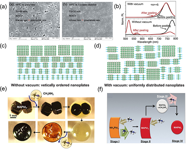
Figure 19. Schematic illustrations of (a) SEM images of perovskite films obtained from 3MAI:PbCl2 precursor, formed on PEDOT:PSS/ITO glass substrates, after thermal annealing in a glove box and a vacuum chamber at 60 °C; (b) photoluminescence (PL) spectra measured before and after peeling for <n>= 5 quasi-2D perovskite films prepared with and without vacuum poling treatment. (c), (d) Schematic diagrams to indicate uniform (c) and ordered (d) formation of different-n-value nanoplates in quasi-2D perovskite films prepared with and without vacuum poling treatment. (e) In situ optical microscope observation of MAPbI3 single crystals interacting with MA gas at room temperature. (f) Proposed mechanism of the thin-film transformation of NH4PbI3 to CH3NH3PbI3 via the methylamine-induced conversion healing process. (a) Reprinted with permission from [178]. Copyright (2015) American Chemical Society. (b)–(d) Reprinted from [180], Copyright (2019), with permission from Elsevier. (e) Reprinted with permission from [181]. Copyright (2017) American Chemical Society. (f) [182] John Wiley & Sons. [Copyright © 2016 WILEY‐VCH Verlag GmbH & Co. KGaA, Weinheim].
Download figure:
Standard image High-resolution imageCH3NH3 (MA) gas can induce the phase transition phenomena of liquefaction and recrystallization, which can heal the defects in the perovskite film, thus forming a dense film with high crystallinity. With respect to the application of MA gas in perovskite film fabrication, Pang et al did pioneering work [181]. In their research, it was found that organic lead halide perovskite can react directly with MA gas to produce a flowing liquid. The methylamine in the liquid can be quickly removed at room temperature when withdrawing the external MA gas, thus making the perovskite regenerate. As shown in figure 19(e), the reaction mechanism is that the strong interaction between MA molecules and iodine in perovskite makes the arrangement of PbI6 in perovskite change from a three-dimensional to low-dimensional structure. The excess methylamine molecules in the material are spontaneously released when the concentration of external methylamine gas becomes low, and the PbI6 is reconstructed in a three-dimensional arrangement structure. This novel phenomenon applied to the preparation process of perovskite film can realize fast repair of defects and the crystal structure reconstruction process in only a few seconds. More importantly, the crystallinity and crystal orientation are improved obviously after reconstruction. Moreover, the MA gas treatment can also cause cation substitution. Zong et al first realized the transformation of NH4PbI3 non-perovskite into MAPbI3 perovskite by adopting the MA gas treatment [182]. Their research proposed the mechanism of thin-film transformation via the MA-induced conversion process, as shown in figure 19(f). When NH4PbI3 non-perovskite is placed in the MA gas environment, an intermediate liquid MAPbI3·xCH3NH2 is formed, and further contact with the MA gas leads to the escape of the pores. After removing the film from the MA gas, the rough perovskite film becomes dense and smooth.
In addition to providing a gas atmosphere in the annealing process, Lee et al introduced a superhydrophobic perfluorodecalin two-dimensional liquid cage with superhydrophobicity during the thermal annealing process, which prevented the evaporation of DMSO physically and played the role of delaying crystallization and increasing grain size [183]. Excellent results can also be achieved by adjusting the annealing conditions, including time and temperature, without introducing additional auxiliary annealing methods (figure 6(b)). Kim et al developed a high-temperature-short-time annealing process of 400 °C, 4 s to quickly remove the residual solvent in the precursor film and obtain a smooth and uniform film with an average domain size of 1 μm [105].
7. Effect of substrates
The surface properties of substrates are expected to affect greatly the crystallization and crystal growth of perovskite film. For mesoporous substrates, hydrophilic substrates facilitate the permeation of precursor solution and good contacts with perovskite crystals [184–186]. Meanwhile, the direct link between grain size controlled by substrates and photovoltaic performance was investigated for both one- and two-step deposited perovskites [187]. As shown in figure 20(a), for a one-step deposition method, the facilitated heterogeneous nucleation on a hydrophilic substrate surface results in increased grain size and high crystallinity. However, in the two-step deposition case nucleation and growth processes occur separately. Perovskite films deposited on a hydrophilic surface by a two-step method exhibit small grain size, leading to a reduction in photovoltaic performance [187]. Therefore, it is necessary to improve the hydrophilicity of the substrate in the one-step deposition method, and the hydrophobicity of the substrate in the two-step method. To improve the hydrophilicity of substrate in the one-step deposition case, oxygen plasma [188], interfacial additives such as poly[(9,9-bis(3'-(N,N-dimethylamino)propyl)-2,7-fluorene)-alt-2,7-(9,9-dioctylfluorene)] [189], poly(ethylene glycol) tridecyl ether [187], biopolymer heparin sodium [190] and aminovaleric acid [184] were applied. As shown in figure 20(b), an efficient method of modifying the ZnO-coated substrate surface with hydrophilic 3-aminopropanioc acid (C3-SAM) was developed to direct the crystallization evolution and achieve the optimal morphology of CH3NH3PbI3 perovskite film deposited by the one-step method [191]. In contrast, hydrophobicity can be improved by applying hydrophobic interfacial additives in the two-step method [192, 193]. As shown in figure 20(c), a ZnO-coated substrate surface was modified by inserting dual-functional self-assembled monolayers (SAMs), which acted both as excellent surface-wetting control layers and as electric dipole layers. The introduction of SAMs enhanced the hydrophobicity of ZnO, which improved the quality of PbI2 layers and the perovskite formation quality [193].

Figure 20. (a) Correlation between PCE (black solid squares), average perovskite grain size (blue open squares), and contact angle of the hole transport layer (left) for one-step deposited and (right) for two-step deposited PSCs. (b) Schematic diagram of SAM-induced permanent dipole formation and involvement of the SAM in the crystalline structure of perovskite crystals. (c) Schematic illustration of enhanced hydrophobicity of ZnO with a self-assembled monolayer for the two-step deposition method. (d) Schematic illustration of the fabrication of Si-integrated MAPbBr3 single crystals. (e) Schematic of the epitaxial structure of CsSnI3 film on KCl (100) (Cs: orange; Sn: gray; I: purple; K: blue; Cl: light green). (f) Epitaxial growth of CsPbBr3 on SrTiO3 substrate. (g) Schematic diagram of the van der Waals epitaxial growth of a MAPbI3 grain on a MoS2 surface. (a) Reprinted with permission from [187]. Copyright (2018) American Chemical Society. (b) Reprinted with permission from [191]. Copyright (2015) American Chemical Society. (c) [193] John Wiley & Sons. [Copyright © 2018 WILEY‐VCH Verlag GmbH & Co. KGaA, Weinheim]. (d) Reprinted by permission from Springer Nature Customer Service Centre GmbH: [Sprigner Nature] [Nature Photonics] [194] (2017). (e) Reprinted with permission from [195]. Copyright (2019) American Chemical Society. (g) [196] John Wiley & Sons. [Copyright © 2019 WILEY‐VCH Verlag GmbH & Co. KGaA, Weinheim].
Download figure:
Standard image High-resolution imageTo increase the bonding between the monomers and the substrates and further modify the crystal growth, for example, Lewis-base sites were introduced on the substrates to improve perovskite crystallization by depositing a hydrophilic group (C–O and C=O) of grafted buffer layers, such as PMMA [197] and poly(ethylene oxide) modified SnO2 quantum dots [198]. As shown in figure 20(d), a successful example was developed to fabricate a Si-integrated MAPbBr3 single-crystal device by inserting a low-temperature solution-processed molecule bind brominated (3-aminopropyl) triethoxysilane (APTES). APTES was combined with a silicon wafer through silicon–oxygen bonding and participated in perovskite crystallization through the NH2-terminated group, yielding a solid mechanical and electrical connection [194].
Moreover, the chemical bonding between the substrate and perovskite layer with similar crystal structures can reduce the energy barrier of heterogeneous nucleation and the surface energy, which preferentially initiates the epitaxial growth of perovskite single crystal. Figure 20(e) shows the epitaxial growth of CsSnI3 on a KCl substrate through a vapor deposition method [195]. As shown in figure 20(f), CsPbBr3 single-crystal epitaxial growth on a SrTiO3 substrate was achieved by a solution spin-coating method [199]. The boundary layer formed by solution spin-coating promotes heterogeneous nucleation, while the ordered anion layer attracted to the substrate surface can further reduce the nucleation activation energy. As the solvent evaporates, the solution becomes supersaturated and then nucleates at the interface, which leads to a concentration gradient along the thickness direction and corresponding ion diffusion, thus promoting perovskite film growth [199]. The intermolecular Pb–S interaction between the perovskite and 2D SnS2 substrate was reported to improve the crystal orientation [200]. Similarly, figure 20(g) shows the van der Waals epitaxial growth of MAPbI3 perovskite films on a 2D MoS2 substrate [196].
With the development of perovskite/silicon tandem solar cells, fabricating dense perovskite film on a textured silicon surface with high-quality interfacial contacts has become important in recent years. The textured structure consists of many pyramids with heights in a range of 1 ~ 10 μm, which is useful for silicon cells with improved light harvesting but exceeds the thickness of traditional PSCs (~0.5–1.0 μm). The fabrication of the dense perovskite film on textured silicon wafer surfaces can be divided into two categories, i.e. (a) growing conformal perovskite layers by combining thermal evaporation with post-solution processing; and (b) filling the textured surface with a thick perovskite layer by solution processing.
Similar to the situation described in figure 4(f), fabricating thin films on a rough surface is challenged by the accumulation of wet films in valley regions and the dewetting of film at the tips. For this reason, Sahli et al first grew a conformal PbI2:CsBr film on textured silicon by thermal co-depositing, and then this uniform PbI2:CsBr film was converted into perovskite film by spin-coating a layer of AX salt (FAI:FABr = 3:1) on top followed by thermal annealing at 150 °C for 30 min [201]. As a key issue to prevent the material from accumulating in the pyramid valleys, the contact time between the conformal PbI2:CsBr film and the AX solution was minimized by using two techniques: first, volatile ethanol was used as a low-boiling-point solvent; and second, a dynamical spin-coating method was employed in which the solution was dropped on a highly rotating substrate (4000 rpm). The resulting conformal perovskite absorber layer was demonstrated to be dense and uniformly thick, so that it was able to fully cover all micrometer-sized silicon pyramids (figure 21(a)).
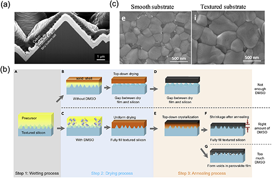
Figure 21. (a) Cross-sectional SEM image of the full perovskite top cell deposited on the silicon heterojunction (SHJ) bottom cell surface morphologies. (b) Mechanism of dense perovskite film formation. (c) SEM images of perovskite film surface morphologies on smooth/textured FTO substrates. (a) Reprinted by permission from Springer Nature Customer Service Centre GmbH: [Sprigner Nature] [Materials] [201] (2018). (b) Reprinted from [93], Copyright (2020), with permission from Elsevier. (c) Reprinted from [202], Copyright (2017), with permission from Elsevier.
Download figure:
Standard image High-resolution image
In contrast to the previous conformal deposition, Huang's team employed a textured silicon wafer with reduced pyramid height of ~1.0 μm and then grew a Cs0.1MA0.9Pb(I0.9Br0.1)3 perovskite film with an improved thickness of over 1.0 μm by all solution methods. Based on this strategy, the valleys between the pyramids were completely filled and the textured silicon substrate was planarized [93]. 2-ME was used as the low-boiling-point solvent and N2 gas flow was used to form fast nucleation after doctor blading. An optimized ratio of DMSO (25 mol%) was reached that obtained a balance between the slowed-down crystallization process of perovskite and the minimized volume shrinkage of the solid film due to DMSO removal (figure 21(b)). In addition, the introduction of surfactants into perovskite precursor solutions inhibited the Marangoni flow in wet film, which also contributed to the formation of dense films.
Shi et al prepared the perovskite film on textured/smooth fluorine-doped SnO2 (FTO) substrates with both sequential thermal evaporation deposition and solution methods [202]. Their research demonstrated that textured substrates with rough surfaces not only enhance light absorption but also promote the conversion of precursor solution to perovskite during the two-step fabrication process. As shown in figure 21(c), the resultant perovskite films on textured FTO substrates are more uniform and have larger grain size (about 700 nm) than on smooth substrates (about 300 nm). The perovskite precursor solution tends to produce heterogeneous nucleation sites on the concave of the substrate, which promotes the formation of larger grains by forming fewer nucleation centers.
8. Conclusions and outlook
The glorious achievements in exploring high-efficiency PSCs have been largely supported by advances in controlling the crystallization process of perovskites. Lots of insights into the formation process of perovskites have been established in the past decade. In this review, the formation of perovskite polycrystalline films has been summarized from the perspective of their influencing factors at different stages, during which some recently updated understanding has been introduced. We would like to highlight that the formation of PbI2-based solvated phase in solution is usually the first stage in the crystallization of perovskite, although its corresponding signal may not be significant sometimes. Engineering the formation of solvated phase or taking advantage of the solvated phase (e.g. slow release of solvents for solvent annealing) helps to control the nucleation and crystal growth of perovskite films. However, insights into how the chemical status of colloid particles in precursor solution influences the defect formation in the resulting films are still worth being explored. Besides aging time and colloid size, other physical parameters, such as surface tension and viscosity, may also need attention.
Generally, controlling the supersaturation is an effective way to control the nucleation density. As alternative strategies, using additives such as AX salts or coordinating molecules are also efficient methods to adjust the precipitation rate of PbI2-based solvated phases. Although the nucleation region can be controlled at the upper or bottom or edge regions of the precursor solution, methods to promote perovskite growing from the substrate upwardly have been relatively less reported, yet might enable good contact between perovskite and bottom structured layers with low density of interfacial micro-cavities. Increasing the interaction between perovskites and substrates to reduce the nucleation energy barrier, together with temperature and concentration gradient control, would be an efficient method.
While using methods to influence solution supersaturation and tune the crystal growth rate are common, strategies to regulating the crystal growth speed through the energy barrier formed at phase boundary regions deserve more investigation in the future, as they might broaden the method to high-quality crystal films. The LaMer mechanism provides a clear picture to understand the competition between nucleation and crystal growth of perovskite in solution, but methods of better control of the supersaturation with wide proceeding windows are still desirable.
For large-area fabrication of perovskite films, remarkable advances have been achieved in recent years; meanwhile, systematic knowledge and well-designed methods of controlling the detailed drying process are key for high fabrication throughput with high yields. Methods for promoting perovskite grain coarsening and healing might offer new strategies to circumvent the contradictions between high crystallinity, high uniformity/denseness, high fabrication throughput and high yield.
Furthermore, the interaction between substrates and perovskites and the hydrophilicity of substrates with their ways to affect nucleation and crystal growth is reviewed. Investigation of epitaxial growth of perovskites on semi-conductive substrates and their application in functional devices is still in its infancy, and is expected to trigger new research directions in the future.
Acknowledgments
Yongbo Yuan thanks the National Natural Science Foundation of China (51673218), the Innovation-Driven Project of Central South University (2020CX006), and the Hunan Provincial Science & Technology Department (No. 2017XK2030) for financial support. Lili Ke thanks the Natural Science Foundation of Hunan Province (2019JJ50776). Shiqiang Luo thanks the Central South University Postdoctoral International Exchange Introduction Program, China Postdoctoral Science Foundation. X R thanks the Postgraduate Research and Innovation Project of Central South University (1053320192763).