


Abstract
We report on a novel single-photon source using a single calcium ion trapped between the end facets of two optical fibers. The optical fibers act as photonic channels, and in addition their metallic jackets provide a trapping electric field for the ion. Our system successfully combines a stable single-atom emitter with fiber optics, demonstrating remarkable compactness and scalability. In consequence, it is very well suited for use in quantum networks, where single ions interface with single photons traveling through optical fibers. We have demonstrated the non-classical character of the photons generated by this efficient source in continuous as well as pulsed mode.
Export citation and abstract BibTeX RIS

Content from this work may be used under the terms of the Creative Commons Attribution 3.0 licence. Any further distribution of this work must maintain attribution to the author(s) and the title of the work, journal citation and DOI.
1. Introduction
The atom–photon interaction plays a fundamental role in quantum networks, where quantum nodes are composed of single atoms and linked via single photons [1]. At each quantum node, optical qubits traveling through optical channels are interfaced with an atomic qubit serving as a localized quantum memory. Therefore, the implementation of an efficient scalable atom–photon interface for quantum nodes has been at the heart of recent research activities in the field.
Probabilistic approaches using interference of fluorescence photons for atomic entanglement have been proposed [2, 3] and intensely pursued experimentally [4, 5]. Entanglement between two distant single ions has been created [6] and teleportation via the established entanglement has been demonstrated [7]. Since these probabilistic schemes only require identical single-photon sources, they present an alternative avenue for large-scale quantum networks in contrast to the more demanding approaches based on cavity QED [8]. Along this line, building a scalable and efficient single-photon source has become an important experimental challenge for implementing quantum networks. In addition to applications in quantum networks, single-photon sources are also essential ingredients in quantum key distribution and optical quantum computing.
Fluorescence-based single-photon sources have been demonstrated in many physical systems including neutral atoms [9], trapped ions [4, 5], molecules [10], quantum dots [11] and NV centers in a diamond [12]. Among these, trapped single ions have significant advantages such as long trapping lifetime, tight confinement in the Lamb–Dicke regime and unparalleled controllability of their quantum states. Furthermore, the consistency and stability inherent to the spectral properties of cooled ions, most notably demonstrated by atomic ion clocks [13], are ideal for a source of indistinguishable single photons. An important figure of merit when using an ion's fluorescence for single-photon generation is the efficiency with which radiation emitted is captured. In this regard, coupling to high numerical aperture (NA) optics is indispensable, which, however, usually hampers the scalability of the system.
A novel way of capturing fluorescence is provided by optical fibers. While the diameter of an optical fiber core is only of the order of 10–100 μm, fiber ends can be brought in close proximity to a fluorescing particle to maximize the NA. Integrated fibers have been used successfully to detect the presence of neutral atoms on a chip [14, 15]. On the other hand, using optical fibers for collecting fluorescence from trapped ions is complicated by the fact that the trapping potential is adversely affected by the presence of dielectrics [16]. Proper shielding and tight integration of the fiber in the trapping structure is required [17, 18]. We have realized a novel system for combining optical fibers with an rf ion trap. It meets the requirements of close proximity of the fiber ends to the ion and negligible distortion of the trapping field. The insertion of an ion between two optical fibers provides a versatile interface between a single ion and fiber-guided photons, opening up the possibility of photonics with single ions. For instance, the architecture of two optical fibers coupled to an ion is ideally suited to the realization of an ion-based quantum repeater [8].
This paper is organized as follows. In section 2, the details of our endcap trap with fiber integration is given. We also show a result of fluorescence spectroscopy using the integrated fibers. In section 3, we employ the fiber-integrated ion trap as a single-photon source in continuous as well as pulsed mode. g(2) cross-correlation measurements are given to prove the quality of our single photons. Finally, we summarize and conclude the work in section 4.
2. Fiber-integrated endcap trap
A schematic representation of the setup is shown in figure 1(a). Apart from the optical fibers, it consists of two concentric pairs of metallic hollow cylinders. Importantly, the inner cylinders play two distinct roles—as trap electrodes and as jackets shielding the fibers. Together with the outer cylinders they form the electrodes of an endcap-type ion trap [19] providing the trapping potential shown in figure 1(b). The fibers are tightly integrated inside the trap structure without breaking its cylindrical symmetry. They are not flush with the end of the cylinders but retracted by approximately 50 μm so that rf-shielding inside the cylinder makes the overlap of the dielectric fibers and the rf-field negligible. Thus, the insertion of the fibers causes almost no disturbance to the trapping field. Moreover, minimizing the exposed dielectric surfaces and shielding the fibers by the metallic jackets prevent the accumulation of stray charges. As a result, we are able to routinely trap a single ion at the center of the setup for several hours. These benefits of the design allow us to bring the two optical fibers as close as 275 μm to a single ion from the opposite sides. The optical fibers in our experiments are a Thorlabs BFH48-200 multimode fiber with a core diameter of 200 μm and an NA of 0.48. By precisely measuring the trap geometry, we determined that the two fibers combined subtend 6% of the full solid angle, only limited by the geometry and not by the fiber's NA. By further reducing the ion–fiber distance to 183 μm, capture of up to 12.3%, only limited by the fiber's NA, is possible without deteriorating the trapping field.

Figure 1. (a) Schematic representation of the fiber-trap setup. Half of the upper electrode structure is cut away to reveal the upper fiber. The outer diameter of the central electrodes is 458 μm, the inner diameter is 254 μm and the vertical distance between the electrodes is 446 μm. (b) Cross-section of the pseudopotential of the trap with fibers, obtained from a finite element calculation. The potential calculation takes the material of the fiber into account with a relative electric permittivity of εr = 2.09.
Download figure:
Standard image High-resolution imageCalcium ions (40Ca+) are loaded from an effusive oven mounted on the side of the trap. The atomic beam is collimated by means of a tube of inner diameter 250 μm, 2.45 mm away from the center of the trap. The atoms are photoionized using a resonant laser at 423 nm and a second laser at 375 nm for the actual ionization [20]. For an rf-amplitude of 200 V, the calculated potential barriers are 2.8 eV in the radial and 2.1 eV in the axial direction. The secular frequencies were measured to be νr = 1.9 MHz and νz = 3.8 MHz for a drive frequency of 14.9 MHz.
The ions are laser cooled on the S1/2–P1/2 transition at λ = 397 nm (figure 2). Lasers with a power of several μW are injected from the side under different angles, red detuned by roughly half the linewidth Γ = (2π)22.3 MHz. The ions may also undergo a periodic oscillation, driven by the rf-trapping field (micromotion), if dc electric stray fields push the ion off the central node of the rf-field. In order to minimize the micromotion, we compensate stray fields by applying dc-voltages to the atomic beam collimator, a small wire mounted on the side of the trap and the rf-ground electrodes. The required dc-voltages are determined by probing the rf-modulation of the fluorescence intensity using UV pump beams in three noncollinear directions [21]. In this way the micromotion is compensated in three dimensions and the ions are estimated to be localized within 0.04λ of the trap rf-center.

Figure 2. Scheme of the relevant transitions in 40Ca+. Light quanta emitted on the resonance transition at 397 or 394 nm (blue wavy lines) are coupled to the optical fiber, providing the photonic source in our experiment. Population trapping due to decay to the D-states is avoided by repumping via the upper P-state (red arrows). The wavy lines represent the spontaneously emitted photons.
Download figure:
Standard image High-resolution imageWith the trapped ion well centered between the fiber ends and the fluorescent light captured and guided by optical fibers, there is no need for additional optics for fluorescence detection. Both fibers running down the trap are connected to atmosphere via vacuum feedthroughs (core diameter 400 μm) at the other ends, which in turn are linked to photomultiplier tubes (PMT, Hamamatsu H5773) by another optical fiber (core diameter 600 μm). We have investigated the photonic properties of light emitted by a singly ionized 40Ca+. Applying a resonant laser beam on the S1/2–P1/2 transition, we continuously generate and observe resonance fluorescence at 397 nm. To prevent population trapping in the D3/2 states, we employ two lasers at 850 and 854 nm. This configuration avoids coherent Raman coupling between S1/2 and D3/2 states and effectively implements a two-level-like system.
Spectroscopy with fiber-based fluorescence detection is demonstrated by scanning the 397 nm laser over the red detuned half of the resonance line of the calcium ion, where laser-cooling occurs. Combining the signals from both fibers, we measure a peak fluorescence count rate of 55k counts per second (cps) against a background of 960 cps due to stray light and PMT dark counts (figure 3). This corresponds to a signal to background ratio (SBR) of 57. While achieving a good collection efficiency and high SBR, the optical access is not compromised at all as the collection optics are integrated into the electrodes. Thus, the combination of endcap trap and optical fibers provides excellent conditions for spectroscopy of a single ion.
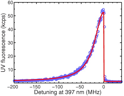
Figure 3. Fluorescence spectrum of a single ion in the fiber-coupled endcap trap. Excitation and repumping beams at a power of 0.39 μW and 0.5 mW, respectively, are injected from the side of the trap. The combined fluorescence of the two fibers is plotted and no background is subtracted. It is fit by a Lorentzian with a half-width of 23.8 MHz (solid line).
Download figure:
Standard image High-resolution image3. Single-photon generation
It is well known that the fluorescent light of a single-atom emitter has non-classical characteristics. They can be probed via the photon statistics which shows perfect antibunching [22]. Antibunched fluorescence from a single atom was first demonstrated in an atomic beam [23] and later with ions [24]. The fact that the second-order correlation function is close to zero at times smaller than the relaxation time of the transition can be interpreted as the emission of photons one by one, separated by the required atomic repumping. This makes a single-driven ion an efficient source of single photons, even though emission occurs at random times.
The fiber-coupled endcap trap allows us to directly investigate the quantum properties of the fluorescent light from a single ion. In our case the arrival times of photons in the two fibers are anticorrelated, as they originate from the same single ion. Our setup is an ideal, miniaturized version of the Hanbury Brown–Twiss experiment. Instead of generating two anticorrelated photon streams with the help of a beam splitter, we use the photons captured by the two optical fibers directly.
We have measured the second-order correlations between photons in the two fibers by sending the PMT outputs to a time-to-digital converter (FAST 7072T). Figure 4 shows a correlation measurement acquired in 40 min. The signal-to-background ratios in the two fiber channels are 75 and 26, respectively. The difference between them is due to a slight angle of the pump beam, scattering different amounts of light into the upper and lower fibers. The background contribution leads to an offset of 0.05 in the normalized correlation function g(2)(τ) (figure 4). After subtracting this offset, we obtain g(2)(0) = 0.05 ± 0.04, an important figure of merit attesting the quality of our system as a non-classical light source. The measured correlation function is in good agreement with the solution of the full master equation of the calcium ion, obtained numerically and also shown in figure 4. The numerical cross-correlation is obtained from a solution of the time-dependent master equation which includes all the Zeeman sub-structure of the S1/2, P1/2 and D3/2 levels [25].
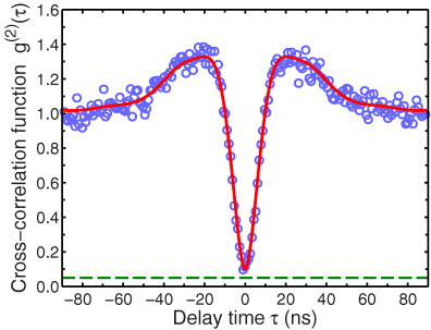
Figure 4. Normalized cross-correlation signal g(2)(τ) of photon arrival times at the end of the two fibers. The driving 397 nm laser is at a power of 0.16 μW and red detuned by 6 MHz from the resonance. The dashed line indicates the expected background level due to stray light and dark counts, which have not been subtracted. The superimposed red curve is obtained from a numerical solution of the master equation.
Download figure:
Standard image High-resolution imageIn addition to generating continuous streams of antibunched photons, we have generated a train of pulsed single photons with a definite temporal profile and periodicity, by pulsing the pump beams [5]. Figure 5 illustrates the scheme for the pulsed single-photon generation. At the beginning of the sequence, we illuminate the ion solely with the 397 nm beam from the side to cool and prepare the ion's internal state into the metastable D3/2 manifold (phase (1) in figure 5). In this phase, the 397 nm laser is applied for 2.5 μs with the 866 nm laser turned off. The excited P1/2-state has a 7.5% probability to decay to the D3/2-state, so that only a few excitations from the ground state are required to shelve the ion in that level with certainty. Subsequently, in phase (2), an 866 nm laser pulse of 1 μs duration follows, transferring the ion back to the ground state along with emission of a single fluorescent photon at 397 nm. The outputs of the PMTs are gated to record only signals in phase (2). The emitted single photons are captured and guided by the other fiber of the pair and then detected by PMTs in a Hanbury Brown–Twiss setup at the output. The sequence is repeated at 250 kHz which results in a count rate of single photons at the PMTs of 332 cps, only limited by the collection efficiency of about 3% and the total detection efficiency of the Hanbury Brown–Twiss setup.

Figure 5. (left) Experimental configuration for the pulsed single-photon generation. A 397 nm laser is injected from the side to cool and prepare the ion in the shelved state. Pulses of the 866 nm repumping laser are sent through the upper fiber. The emitted 397 nm single photons are captured and guided by the lower fiber. The output of the fiber is filtered with a dichroic mirror and spectral filters to eliminate light at 866 nm and then detected by two PMTs in the Hanbury Brown-Twist configuration. (right) Timing charts of the two lasers and level diagrams with transition channels for the two alternating phases in the sequence.
Download figure:
Standard image High-resolution imageThe cross-correlations of photon arrival times are shown in figure 6(a). The total counts P1(t) and P2(t) at the PMTs are composed of contributions from the ion-originated photons p1(t), p2(t) and background events d1(t), d2(t). Hence P1(t) = p1(t) + d1(t) and P2(t) = p2(t) + d2(t). Therefore the cross-correlation of real photons, i.e. 〈p1(t)p2(t + τ)〉 can be written as

Immediately after measurements with an ion, reference measurements were taken with the background signal only. In order to deduce the terms 〈d1(t)P2(t + τ)〉, 〈P1(t)d2(t + τ)〉 and 〈d1(t)d2(t + τ)〉 in (1), the photon arrival times in these reference measurements are cross-correlated with those from the main measurements. As a result the background contribution in a cross-correlation histogram is obtained as 〈d1(t)P2(t + τ)〉 + 〈P1(t)d2(t + τ)〉 − 〈d1(t)d2(t + τ)〉. As shown in the inset of figure 6(a), after subtraction of the background contributions no net positive cross-correlations around τ = 0 have been observed, indicating that our single-photon source is nearly perfectly free from higher photon number contaminations. The results are comparable with what has been achieved in considerably more complex experiments with ions in macroscopic optical cavities [26, 27].

Figure 6. (a) Cross-correlations of photon arrival times at the two PMTs. The bin size of the histogram is 100 ns. The contributions from the detectors' dark counts and scattered light have been removed with the help of independently measured background signals (see text). The inset shows zoom-in around the 0-time delay. The small negativity arises due to subtraction of the random background contributions. The mean value over this region is −0.13. (b) Temporal shape of the single-photon pulses delivered via the optical fiber (blue circles) obtained by measuring the arrival time statistics of photons with respect to the infrared trigger pulse (cf figure 5). The red curve is a fit based on the three-level master equation.
Download figure:
Standard image High-resolution image
We have been able to reconstruct the temporal shape of the single-photon pulses from the recorded detection times (figure 6). The result is fit with a numerical solution of the time-dependent master equation neglecting the Zeeman sub-structure of the S1/2, P1/2 and D3/2 manifolds i.e. they form a three-level lambda system. The resulting Rabi frequency is 7.18 MHz and the detuning is 26.9 MHz to blue for the infrared laser. It shows a decay time of 230 ns, proving a good temporal localization. The temporal shape can be, in principle, arbitrarily controlled by tailoring the shape of the 866 nm pulse [27]. Note that our experimental configuration implements, from the user's point of view, a unidirectional 'fiber-in–fiber-out' single-photon source—an infrared pulse sent through a fiber is converted into a single UV photon and it emerges from the other end. This plug-and-play feature could be significantly useful for future quantum networks using single ions and fiber-carried single photons.
4. Conclusion
In summary, we have constructed a novel photonic system that tightly integrates optical fibers and a state-of-the-art ion trap. We have achieved reliable storage of a single ion in close proximity to the two optical fibers. This shows that the geometry as implemented here is an ideal way to overcome the fundamental problem of dielectric materials distorting the rf-trapping field. The fluorescence of a single ion is directly captured by a pair of fibers only 270 μm away from the ion. Connecting each fiber to a photomultiplier tube provided us with a highly efficient detection system which is easy to maintain, as no optical adjustments are required. We have analyzed the photon statistics of resonance fluorescence as well as of pulsed single photons from a single ion and have observed strong antibunching in both cases. This system not only works as an efficient detection system for the trapped ion but also serves as a compact fiber-based single-photon source. The plug-and-play feature demonstrated in pulsed single-photon generation is particularly well suited for quantum networking. In quantum networks, where mode matching of photons from independent sources is required, the use of single-mode fibers is likely to be necessary. Our fiber-trap system can be easily modified to accommodate single-mode fibers with appropriate mode matching optics such as fiber-end lenses [28] or mirrors [29].
Acknowledgments
We gratefully acknowledge support from the European Commission (Marie Curie Excellence grant no. MEXT-CT-2005-025703), the EPSRC (EP/D061296/1) and Japan Science and Technology Agency (PRESTO).