


Abstract
We demonstrate the control and rotation of an optically trapped object, an optical paddle-wheel, with the rotation direction normal to the beam axis. This is in contrast to the usual situation where the rotation is about the beam axis. The paddle-wheel can be optically driven and moved to any position in the field of view of the microscope, which can be of interest for various biological applications where controlled application of a fluid flow is needed in a particular location and in a specific direction. This is of particular interest in signal transduction studies in cells, especially when a cell is flat and spread out on a surface.
Export citation and abstract BibTeX RIS

Content from this work may be used under the terms of the Creative Commons Attribution 3.0 licence. Any further distribution of this work must maintain attribution to the author(s) and the title of the work, journal citation and DOI.
GENERAL SCIENTIFIC SUMMARY Introduction and background. Optical tweezers, where a tightly-focused laser beam is used to trap and manipulate transparent microscopic particles, can be used to exert torques as well as forces. This can allow trapped particles to be rotated, and constant steady rotation is possible. Such rotation results in fluid flow about the particle, which can be used to exert forces on nearby objects. However, such rotation is typically about the beam axis, and the flow due to rotation above and below the particle is small. Rotation about a horizontal axis would produce larger flows above and below, and be better suited for many applications. One way to achieve this type of rotation is to make an optically-driven paddle-wheel.
Main results. We used two-photon photopolymerization to produce such a paddle-wheel, and demonstrated control and rotation using multiple-beam traps produced both by independent independently-steerable beams, and by a spatial light modulator (SLM). 6mW of driving power is sufficient to exert 1pN of force on an object under the paddle-wheel.
Wider implications. In contrast to the usual situation where rotation is around the beam axis, the paddle-wheel rotates about a horizontal axis. This is of particular interest in mechanobiology, for example in signal transduction studies in cells, especially when a cell is flat and spread out on a surface. In addition, the force exerted on the cell can be switched on and off quickly, can be known, and can be controlled, and small constant forces can be exerted.
 Figure. (a) Optically-driven paddle-wheel positioned above a cell spread out on a microscope slide. The paddle-wheel will exert a horizontal force on the cell. (b) SEM image of microfabricated paddle-wheel. (c) Paddle-wheel held in an optical trap and rotated. The position of the driving beam is indicated by the red cross. The scale bar is 3μm.
1. Introduction
Mechanotransduction, where cells produce a biochemical signal in response to mechanical stimuli, is important in a broad range of cellular functions, as well as in specialized cells such as sensory hair cells in the inner ear (Ingber 2006). For example, defects in mechanotransduction have been implicated in a variety of diseases (Jaalouk and Lammerding 2009). The mechanical stimuli to which cells respond include forces or shear stress due to fluid flows, which can be important in endothelial cells in the vascular system (Davies 1995). Research studying such mechanotransduction typically uses flows resulting in shear stress of about 1 N m−2, but effects have been observed for shear stresses as low as 0.02 N m−2. Fluid flow has also been shown to be able to direct the growth of axons (Wu et al 2012); in this case, the shear stress was 1.2−3 N m−2, and the total force acting on the growth cone of the axon was about 0.17 pN. A device allowing a shear stress and force that is controllable in both magnitude and direction can be a valuable tool for further studies on mechanotransduction. Since optically-trapped objects can be rotated by the transfer of angular momentum from the trapping beam to the object (Parkin et al 2007), creating a flow in the surrounding fluid, they are a promising tool for mechanobiology, since they offer a controllable and localized flow, and the resulting shear stress and applied force can be known. In comparison to using a mechanical probe, where the contact force between the probe and cell depends on the response of the cell and cannot be known a priori, the force due to an optically generated flow is steady. In addition, such a force can be switched on or off in a time on the order of microseconds. Very small forces—which have been shown to affect cells (Wu et al 2012)—can be exerted, opening new possibilities in low-force mechanobiology. Since the response of an organism depends on the force applied, this significantly increases the versatility of such probes.
However, optically driven rotors typically rotate about the beam axis; thus, in a conventional optical tweezers microscope setup, about a vertical axis above a horizontal microscope slide. This is not the most convenient geometry for exerting flow-induced forces on a cell spread along the slide, from above. The shear stress field is ring-shaped, so that the pattern of shear forces on the top of the cell is complex, and the total force exerted on the cell is zero, no matter how large the shear stress is. These problems can be overcome if the optically driven rotor is rotated about a normal axis, which in a conventional optical tweezers requires rotation about an axis normal to the beam axis. Horizontal and vertical rotation can be compared by approximating the rotating object as a sphere, which gives a simple analytical result for the flow (Landau and Lifshitz 1987). The interaction with the nearby surface can be approximated using an image sphere situated below the surface. A comparison between the two cases is shown in figure 1, for a sphere 1 radius away from the surface (i.e. the centre of the sphere is two radii away), assuming a uniform isotropic fluid of constant linear viscosity and no-slip boundary conditions. While there is a clear quantitative difference—the shear stress is 3.5 times greater for horizontal flow—it is the qualitative difference that is more important: the shear stress field has a simple pattern, with maximum stress being exerted in the middle. In particular, since the stress vector lies everywhere in the same direction, the force exerted on the surface (e.g. on a cell below the rotor) is non-zero.
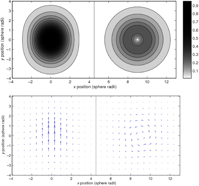
Figure 1. Shear stress exerted on a surface below a rotating sphere. The left hand side shows the shear stress due to a sphere rotating about a horizontal axis, and the right hand side shows the shear stress due to rotating about a vertical axis. The rotation rate is the same in both cases. The sphere is 1 radius away from the surface. For horizontal rotation, the maximum shear stress is 3.5 times greater than for vertical rotation for the same rotation rate, independent of the sphere–surface distance. More importantly, the total force due to horizontal rotation is non-zero, while the total force due to vertical rotation is zero, no matter how large the shear stress is.
Download figure:
Standard image High-resolution imageThis force is a function of distance below the rotating object, the rotation rate and the viscosity of the fluid, and, with a suitably calibrated system, will be known. The calibration can be based on computational simulation of the flow, as presented below, or on measurements of the flow, e.g. using tracer particles.
It is possible to design and fabricate an object that can be optically trapped and rotated about a horizontal axis. For practical use for exerting force or shear stress on cells, it is important that the device be movable, ideally with an optical trap, since cells adhering to a cover slip or petri dish cannot be easily moved to the device. We can summarize the requirements as (a) rotation about a horizontal axis, (b) the rotation must be controllable and (c) it must be possible to control both the position and orientation of the device in three dimensions.
Since rotation about the beam axis is easily achieved using either spin (Friese et al 1998) or orbital (Asavei et al 2009) angular momentum, we can consider trapping geometries using horizontal beams. Such traps predate optical tweezers (Ashkin 1970), and have been implemented under the microscope (Guck et al 2001, Knöner et al 2006). However, such traps are not simply movable, and offer only one-dimensional position control of the trapped object. Therefore, horizontal beam traps do not appear to be suitable.
A device that will be trapped and driven by vertical beams requires rotation about an axis normal to the beam axis. This has been achieved in the past using paddle-wheel-like structures (Higurashi et al 1998, Gauthier et al 2001, 2002, Kelemen et al 2006, Metzger et al 2011). Thus, paddle-wheels that are fixed in place by an axle (Gauthier et al 2002, Kelemen et al 2006, Metzger et al 2011) are unsuitable. Free paddle-wheel devices have been designed and tested, but these have also been unsuitable. The design by Gauthier et al (2001) requires counter-propagating beams, and that by Higurashi et al (1998) (with the 'paddles' on the inside) does not present a reliable method for orientation control, or a method of controlling the rotation rate other than by changing the power of the trapping beam. Where the rotation rate is proportional to trapping power, the rotation cannot be stopped (or made very slow) while keeping the device trapped. However, freely-movable devices like these point the way forwards. The additional features required are three-dimensional (3D) control of the orientation, and separate beams for trapping and moving, preferably with all beams focused by the same objective lens.
Trapping and control of the position and orientation that is independent of the driving beam can be achieved by using 'handles', such as spheres attached to the rotor. Handles of this type have been used for the control of both natural and microfabricated objects (Phillips et al 2011, Palima et al 2012). As long as the handles are rotationally symmetric about the paddle-wheel axis, the device can be a single piece, since rotationally symmetric handles can freely rotate with the rest of the device. This restricts the device to handles along the axis; therefore, two handles are optimal.
In this paper we report the design and fabrication of a micrometre sized paddle-wheel with two spherical handles using this method. The paddle-wheel can be optically driven and moved to any position in the field of view of the microscope. For example, it can be positioned above a cell on a microscope slide, and driven to exert a shear stress on the upper surface of the cell, as depicted in figure 2.
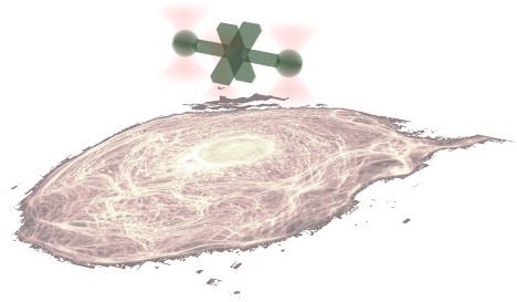
Figure 2. Optically-driven paddle-wheel positioned above a cell spread out on a microscope slide. The paddle-wheel will exert a shear stress, and consequence force, on the cell as shown in figure 1.
Download figure:
Standard image High-resolution imageWe fabricate the paddle-wheel using two-photon photopolymerization, which, following its advent in 1991 (Strickler and Webb 1991), has been used to produce 3D microstructures (Maruo et al 1997), including various micromachines (micropumps, microneedles, microgears) with resolution in the order of 100 nm (Galajda and Ormos 2001, Maruo et al 2003, Maruo and Inoue 2006), and has proved to be a powerful technique for creating micrometre sized objects of arbitrary shape.
2. Paddle-wheel design and fabrication
The paddle-wheel was fabricated by means of two-photon photopolymerization of UV curing resins. A detailed description of the fabrication setup and method can be found in a previous publication (Asavei Nieminen Heckenberg and Rubinsztein-Dunlop 2009). Essentially, micrometre sized structures can be fabricated by using two-photon excitation of UV absorbing liquid resins. The use of two-photon excitation instead of one-photon is essential because in this way precise optical sectioning can be achieved and hence 3D micro-objects can be fabricated with high spatial resolution. We used a commercially available optical adhesive, NOA63 (Norland Products Inc., NJ, USA) which is a highly viscous resin that can be cured with UV light. After curing, the resin is highly transparent in the visible and near infrared (IR) range making it ideal for optical tweezers experiments.
We using a femtosecond pulsed IR laser (Tsunami, Spectra Physics) with a wavelength of 780 nm for two-photon excitation. Figure 3 shows our initial 3D computer aided design of the paddle-wheel (right), which is used general a series of 2D bitmaps (left). Each bitmap represents a horizontal slice through the object, 200 nm apart. These are used as input for the photopolymerization computer program. The stage is moved so as to raster scan the (stationary) focal point of the beam over each layer, beginning with the lowest layer. The raster scan was performed under continuous motion. Where there are black pixels on the 2D bitmaps, a shutter is opened, allowing the beam to photopolymerize the resin, producing a voxel (volume element). The pixels are 100 nm apart in the horizontal directions. After a layer is completed, the stage is moved 200 nm in the vertical direction, and the process is repeated. The photopolymerized voxels are approximately 170 nm wide and 500 nm tall, and therefore overlap, producing a solid structure. A single micro-structure is produced in 25 min with a threshold photopolymerization average power of 18 mW. After photopolymerization the sample is washed with acetone in order to get rid of the unpolymerized resin.
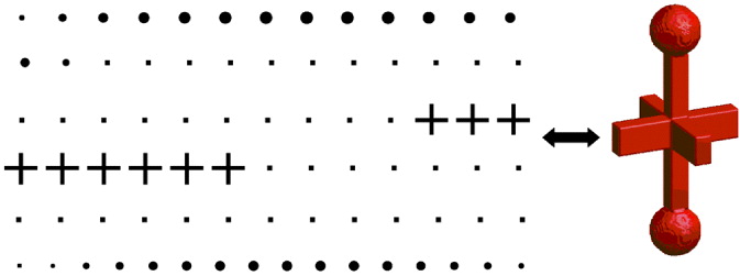
Figure 3. 3D CAD model of the paddle-wheel and two-dimensional (2D) bitmap slices of the object used for microfabrication. On the left are the bitmap slices of the object. If these are stacked with a 200 nm separation in order, beginning with the top row from left to right, then continuing along the next row from left to right, through to the bottom row, a structure like the 3D model will be formed. Both the axial and transverse motions of the photopolymerization process were done in a raster scan mode for 200 and 100 nm separations respectively. The raster scan was performed under continuous motion, the shutter of the polymerization beam closing only when white pixels were detected and was opened for black pixels.
Download figure:
Standard image High-resolution imageThe paddle-wheel was designed such that it could be horizontally trapped and rotated such that one could obtain a flow in a plane parallel to the rotation axis. Trapping the paddle-wheel horizontally can be achieved by means of dual-optical tweezers if the paddle-wheel has a dumbbell shape. Once trapped a third beam could push the paddle and hence rotate it.
The object consists of 81 layers each separated by 200 nm in the z-direction, resulting in a length of 16 μm. The two spheres at the ends were chosen to have a diameter of 3 μm. The paddles have a length of 4 μm, a height of 2 μm and a width of 1 μm and the stalks on each side of the paddle have a 1 × 1 μm2 rectangular profile. In figure 4 is shown a microfabricated paddle-wheel immediately after its fabrication and after the acetone wash. Since the bitmap model assumes that the voxels have an aspect ratio of 2, and the actual aspect ratio is about 4, the parts of the device are elongated along the axis compared with the model. This does not significantly affect the functioning of the rotor.
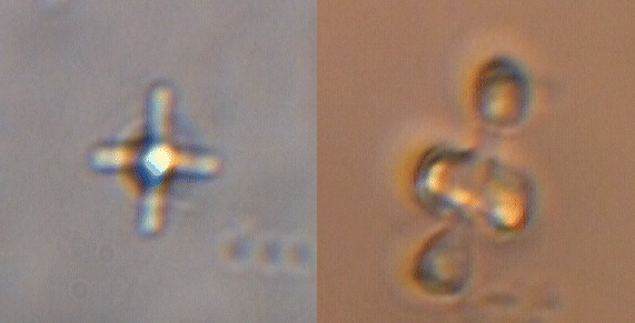
Figure 4. Bright field microscope image of a microfabricated paddle-wheel in unpolymerized resin (left) and after acetone wash (right).
Download figure:
Standard image High-resolution imageScanning electron microscope (SEM) images of typical microfabricated paddle-wheels, both attached to the cover slip and fallen due to hydrodynamic forces during the acetone wash, are shown in figure 5. A closer look at the surface of the objects reveals a smooth surface with small variations in the order of 100 nm.
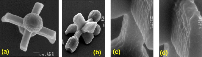
Figure 5. SEM images of microfabricated paddle-wheels. Panel (a) shows a paddle-wheel end-on, and panel (b) shows a paddle-wheel at an oblique angle. Panels (c) and (d) show details of the paddles.
Download figure:
Standard image High-resolution imageThe paddle-wheel is lifted from the cover slip by mechanical force using the tip of a needle and then used in trapping and rotation experiments in water.
3. Experimental setup
The experimental setup used for trapping and rotating the paddle-wheel is based on a fully steerable dual-trap optical tweezers system (Fällman and Axner 1997) which allows independent movement of the trapped object in x and y directions and, most importantly, in the z-direction. A schematic diagram of the experimental setup is shown in figure 6. For dual trapping, the output from a CW Yb doped fibre laser (λ = 1070 nm, IPG Photonics) is split into two beams by means of a polarizing beam splitter cube (PBS) and then recombined through a second PBS and the two gimbal mounted mirrors (GMMs) in order to enter the microscope objective (100 × , NA = 1.3, non-infinity-corrected, Olympus). By imaging the objective entrance aperture onto the centre of each GMM by the lenses L3 and L4, the two traps can be steerable in the x and y directions. Furthermore, if an afocal telescope is placed in each of the two arms (between PBS and GMM—see figure 6) the two traps can also be moved independently in the z-direction. The change in the z position of the traps as a function of the change in the distance between L1 and L2 is given by (Fällman and Axner 1997)

where fo is the focal length of the objective and Δd12 is the distance that lens L1 in figure 6 is moved. In our configuration we find that moving lens L1 by 1 cm the traps move 20 μm in the z-direction. Rotation of the paddle-wheel is achieved by a third beam, independent of the two traps. We use the IR output from the Ti:sapphire laser (λ = 780 nm, Tsunami, Spectra Physics) pumped by a CW solid state laser at 532 nm (Millenia, Spectra Physics). For successful rotation of the paddle-wheel, the Ti:sapphire laser has to be operated in CW mode. For convenience, the third beam was also steered in x and y in the same manner as described above.
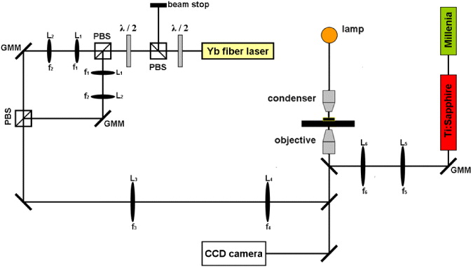
Figure 6. Schematic of the experimental setup used for trapping and rotating the paddle-wheel. A beam from the Yb fibre laser is split into two paths, each with a GMM for x and y steering, and a telescope (L1 and L2) for steering in z. The beams are recombined, and focused by the objective (100 × , NA = 1.3, Olympus) and used to trap the spherical handles of the paddle-wheel. A third beam, from a Ti:sapphire laser, with steering capability, is used to drive the rotation of the paddle-wheel.
Download figure:
Standard image High-resolution image4. Paddle-wheel optical rotation
As mentioned above, the steering in the z direction of the two traps is of importance due to the chromatic aberration of the microscope objective. We found that the difference between the focal point at 1070 and at 780 nm is 6 μm; this large difference is probably due to differences in the collimation of the beams from the two lasers, as well as chromatic aberration. In this configuration, even if we could trap the paddle-wheel, we could not achieve any rotation from the third beam due to the large difference in z between the foci. Therefore, to rotate the paddle-wheel one needs to bring the foci of the three beams closer in the z direction. To do so we trap 4.5 μm polystyrene beads in the three traps and we adjust the z position of the dual traps with respect to the 'pushing' beam until all three beads are in focus. Figure 7 shows images of the three beads without and with z steering respectively. Also, by x and y steering we can arrange the three beams in the optimal geometry for trapping and rotation.

Figure 7. Bright field microscope images of 4.5 μm diameter polystyrene beads trapped in the three beams before (left) and after (right) z steering of the dual optical trap.
Download figure:
Standard image High-resolution imageIn the above configuration, the trapped paddle-wheel could be rotated by the 'pushing' beam impinging on the edge of the paddles as shown in the schematic of the experiment in figure 8. The 'pushing' beam should not be too tightly focused, or the individual paddles will be trapped by the axial gradient force. On the other hand, the waist of the 'pushing' beam should not be too large, or too much light will miss the paddle (or worse, illuminate the opposing paddle on the other side of the axle). The 'pushing' beam size can be controlled by appropriately underfilling the back aperture of the objective with this beam.

Figure 8. Schematics of the trapping and rotation of the paddle-wheel. Two beams from a 1070 nm laser are used to trap the spherical handles, and can be independently steered in three dimensions to control the position and orientation of the device. A third beam, from a 780 nm laser, is used to drive the paddle-wheel. Since the 'pushing' beam is from a separate source, its power can be changed, or the beam turned off, without interfering with the trapping of the paddle-wheel.
Download figure:
Standard image High-resolution imageIn figure 9 are shown consecutive frames of the rotating paddle-wheel with a rotation rate of 2 Hz. The power of the 'pushing' beam was 40 mW at the sample.

Figure 9. A sequence of bright field microscope images of the rotating paddle-wheel. The frames are 140 ms apart. In the first frame the position and propagation direction of the 'pushing beam' is indicated by the marker on the paddle. The scale bar is 3 μm.
Download figure:
Standard image High-resolution imageThe paddle-wheel was held almost stationary by the trapping beams, apart from the rotation. The standard deviation of the positions of the two ends of the paddle-wheel were 0.66 and 0.11 μm; this includes the effects of Brownian motion and movements of the spherical ends due to rotation since the paddle-wheel is not perfectly straight (as can be see in figure 9). The rotation could be unsteady, since the paddles are not identical, and with only four paddles, the pushing force is not constant. Image analysis of video of the rotating paddle-wheel when the mean period of rotation was 2.07 s shows a standard deviation of rotation period of 1.05 s.
5. Rotation of the paddle-wheel using a spatial light modulator
The paddle-wheel could also be trapped and rotated using a spatial light modulator (SLM) to create multiple trapping beams (Grier 2003, Leach et al 2006) from a single laser beam. By replacing the GMM in figure 6 with an SLM (Holoeye, model HEO 1080 P), as shown in figure 10, one can obtain multiple trapping beams from a single incident laser beam. This can be achieved by diffraction of the incident beam by a computer generated hologram (or phase mask) as seen in figure 11. The three spots on the right in figure 11 are the trapping beams (the left and right beams) and the driving beam (centre) in the first order diffraction. A zero order beam and second-order driving beam can also be seen but these are significantly weaker as the phase mask is blazed. The control program easily allows the independent or coupled movement of the three foci in three dimensions, ideal for this application. This can be achieved by the 'gratings and lenses' (Liesener et al 2000) algorithm implemented in the program (Preece et al 2009) which allows the user to interactively generate holograms that produce multiple spots. By controlling the phase of the grating in the hologram plane the user can shift the beam laterally in the sample plane and similarly the axial shift of the beam is achieved by the phase of the lens in the hologram plane. Since the SLM is in the conjugate plane of the optical traps. It is possible to vary the effective numerical aperture of system by restricting the area of the hologram displayed on the SLM. This can be done independently for each optical trap by setting pixels outside a certain area to zero phase or by using an appropriate multiplicative mask (Jesacher et al 2007). Each optical trap can also be attenuated separately so that the total optical power may distributed between the traps independently. This system also allows the user to change the ratio between the axial trapping force and the scattering force on the paddle wheel.
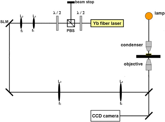
Figure 10. Schematic of the experimental setup used for trapping and rotating the paddle-wheel using a SLM. The setup is similar to that shown in figure 6, with one GMM replaced by an SLM. The three beams can be steered in three dimensions using the SLM, and lenses L1 and L2 are used to optimally illuminate the SLM.
Download figure:
Standard image High-resolution image
Figure 11. Computer generated phase mask used on the SLM display to create three trapping beams (left). The outer portion of the hologram produces the two beams which trap the spherical handles. The inner circular region, in addition to contributing to the trapping beams, also produces the 'pushing' beam. The smaller the radius of the circle, the larger the focal spot of the 'pushing' beam. On the right are the three beams generated by the SLM as seen through reflection of the focused beams by the cover slip. The spots are not perfectly symmetric due to aberrations—no aberration correction was used—and appear as crosses since they are tightly focused when reflected from the cover slip.
Download figure:
Standard image High-resolution imageThe paddle-wheel could be trapped and rotated as seen in figure 12 with the three beams produced by the SLM and it achieved a rotation rate of 0.3 Hz with approximately 6 mW of 'pushing beam' power. The value of the rotation rate from this experiment is consistent with the one described in section 4 in the sense that the rotation rate is proportional to the laser power through the same constant.
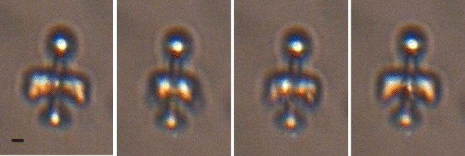
Figure 12. Snapshots of the rotating paddle-wheel by means of the SLM showing a quarter of a full rotation at 0.3 Hz. The scale bar is 1.5 μm. See movie 1 in the supplementary data for video (available from stacks.iop.org/NJP/15/063016/mmedia).
Download figure:
Standard image High-resolution imageA great advantage of the SLM is that the pattern of three spots can be rotated or moved about as a unit which will allow the paddle-wheel to be brought up to a cell and the flow directed in the desired direction in a very convenient way.
6. Hydrodynamic simulations
Knowing the rotation rate we could describe the fluid flow created by the spinning paddle-wheel and could calculate the total drag torque opposing the optical torque. This can be done by solving the Stokes–Navier equation for a Newtonian fluid. An analytical solution of this equation exists only for a limited number of objects (sphere, spheroid, infinite cylinder) and hence in order to compare the experimental results of the optical torque with the counteracting drag torque we need to perform hydrodynamic simulations of the fluid flow generated by the paddle-wheel. Steady-state very low Reynolds number flow can be described by the Laplace equation (Landau and Lifshitz 1987). We can reduce our problem to steady-state flow by using a rotating reference frame in which the rotor is stationary and the distant fluid rotating at a uniform angular velocity about the axis of the rotor. The inertia of the fluid can be neglected due to low Reynolds number, and therefore it is not necessary to introduce fictitious forces due to the rotating frame. We assume non-slip boundary conditions. We use the FlexPDE program (PDE Solutions Inc., Antioch, CA, USA) which is a partial differential equation solver based on finite element numerical analysis. The program constructs a tetrahedral finite element mesh over the geometry specified by the user and then solves the differential equation numerically refining the mesh and the solution until the user-defined error bound is achieved. Since the mesh is over a finite volume, we introduce an outer rotating boundary. The geometry chosen for our system was such that the microstructure was embedded in a cylinder with a diameter of 16 μm and a height of 20 μm as seen in figure 13. Thus, the flow field can be simulated and the drag torque τd, which is the shear torque exerted by the fluid, can be found by integrating the shear stress tensor, multiplied by the distance from the centre of rotation, over the outer cylindrical boundary.
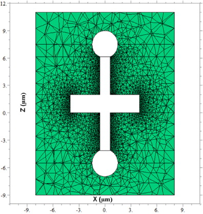
Figure 13. Cross section of the simulated surrounding medium through the xy plane. The paddle-wheel remains stationary, and a cylindrical outer boundary, at the outer edge of the computational mesh, rotates at a uniform angular velocity.
Download figure:
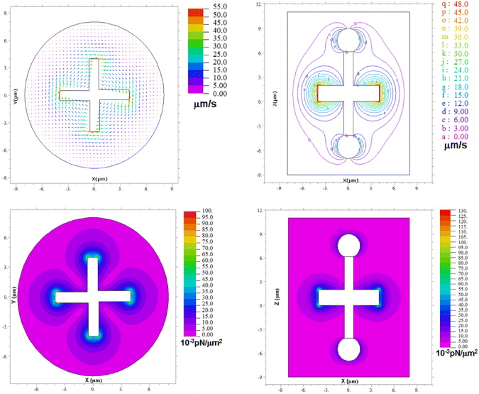
Standard image High-resolution imageTypical graphical outputs of the program are shown in figure 14 where the flow field around the rotating object is simulated as well as the shear stress field (the shear force acting per unit area) which is used to calculate the torque. The simulated drag torque for the rotating paddle-wheel was found to be τd = 10 pN μm for a rotation speed of 0.3 Hz. The accuracy of the method was checked by simulating the drag torque experienced by a rotating sphere in a similar geometry. The difference between the simulation and the analytical solution was less than 0.5% for this case.
Figure 14. Typical graphical outputs of the FlexPDE program. Cross sections through xy (up, left) and xz (up, right) planes of the simulated flow field around the rotating paddle-wheel. Similarly the cross sections through the same planes for the shear stress field are depicted in the lower row. The flows shown are transformed to a reference frame where the paddle-wheel rotates, and the outer boundary is stationary.
Download figure:
Standard image High-resolution image
7. Theoretical modelling
Since the paddle-wheel is rotating with constant angular velocity, the drag torque and the optical torque due to the beam should be equal. Due to the geometry of our system we can state that the optical torque is in fact a mechanical torque due to the force created by the reflection and absorption of the 'pushing' beam at the water–resin interface impinging on the arm of the paddle-wheel. Therefore, the experimentally measured rotation rate, along with the computed drag coefficient, allows us to test computational or theoretical modelling of the optical torque.
It is possible to calculate the optical torque using computational electrodynamics. We calculated the response of the paddle-wheel to the pushing beam using a DDA/T-matrix method (Asavei et al 2009, Loke et al 2009). The torque depends on the position and beam waist of the 'pushing' beam, and it is possible to choose plausible values (i.e. within experimental uncertainty of our best estimates) to reproduce the measured torque. Since the uncertainty of the 'pushing' beam waist is large, there is significant freedom in choosing the final value of the torque, and this agreement should not be regarded as conclusive. Therefore, further verification by another approach is highly desirable.
We can also estimate the torque with a simple optical model. The torque driving the paddle-wheel results from reflection and absorption (if present) of the driving beam by the paddles, and can therefore be expressed as

where nw is the refractive index of water, P is the power of the beam impinging on the paddle, R is the power reflection coefficient of the resin–water interface, A is the absorption coefficient of the paddle and d is the paddle moment arm.
We can neglect the torque due to the absorption due to the low absorption coefficient of the resin (which is approximately 10% lower than that of water at 780 nm) and we can approximate the reflectance R by

with nr being the refractive index of the polymerized resin (nr = 1.56).
We obtain for the optical torque in this approximation τo = 9 pN μm which is in good agreement with the simulated drag torque.
We should mention that this approximation assumed that paddle intercepts the whole beam, and that the beam was at a normal incidence on the paddle. The actual 'pushing' beam is focused (although not as tightly as a typical optical trapping beam), so the momentum flux is lower than for a parallel beam. However, a focused beam will be more strongly reflected, partly compensating for this.
We can also simply estimate the force and shear stress exerted on the surface. If we consider an object in steady-state rotation mid-way between two infinite planes, about an axis parallel to the planes, the drag torque exerted on the planes will equal in magnitude to the drag torque on the object. Since the force is localized, we can approximate the force F on each surface by F = τ/(2h), where h is the distance from the rotation axis to each plane, and τ is the torque on the rotor. Since the torque on our paddle-wheel was 10 pN μm, the force exerted on each surface would be 1 pN if h is 5 μm, This is a reasonable estimate of the force on a single surface when the paddle-wheel axis is this distance away. To estimate the peak shear stress, we can assume the force is localized over a region of 5 μm × 5 μm, giving a peak shear stress of 0.04 N m−2.
8. Conclusion
We have demonstrated the fabrication of an optical paddle-wheel by means of two-photon photopolymerization, and tested the performance of it. We demonstrated the control and rotation of such a device using multiple-beam traps produced both by independent independently-steerable beams, and by a SLM. In contrast to the usual situation where rotation is around the beam axis, here we demonstrate rotation normal to this axis. This is of particular interest in mechanobiology, for example in signal transduction studies in cells, especially when a cell is flat and spread out on a surface. In addition, the force exerted on the cell can be switched on and off quickly, can be known, and can be controlled, and small constant forces can be exerted.
The force and shear stress exerted on a cell by the paddle-wheel under our test conditions would have been 1 pN and 0.04 N m−2 respectively. These would have been attained with our driving power of 6 mW. The force and stress will be linear with the driving power, and order of magnitude greater force and stress can be easily achieved. Even at 6 mW, the force and stress are sufficient for observable biological effects (Davies 1995, Wu et al 2012).
Finally, while we used two-photon photopolymerization to produce our paddle-wheel, it is possible to use other methods for fabrication, and other methods may be better suited for manufacture of large numbers of devices.