
Abstract
Compliance can increase the thrust generated by the fin of a bio-inspired underwater vehicle. To improve the performance of a compliant fin, the compliance should change with the operating conditions; a fin should become stiffer as the oscillating frequency increases. This paper presents a novel variable-stiffness flapping (VaSF) mechanism that can change its stiffness to maximize the thrust of a bio-inspired underwater robot. The mechanism is designed on the basis of an endoskeleton structure, composed of compliant and rigid segments alternately connected in series. To determine the attachment point of tendons, the anatomy of a dolphin's fluke is considered. Two tendons run through the mechanism to adjust the stiffness. The fluke becomes stiffer when the tendons are pulled to compress the structure. The thrust generated by a prototype mechanism is measured under different conditions to show that the thrust can be maximized by changing the stiffness. The thrust of the VaSF device can approximately triple at a certain frequency just by changing the stiffness. This VaSF mechanism can be used to improve the efficiency of a bio-inspired underwater robot that uses compliance.
Export citation and abstract BibTeX RIS
1. Introduction
To increase the dynamic performance of underwater vehicles, the undulating body motion and oscillating caudal fin motion of fish and aquatic mammals have been studied and used to design robotic fish. Robotic fish should have a large number of degrees of freedom to generate traveling waves for effective propulsion. Multiple joints and rigid links with actuators have been used to create various undulating motions (Barrett 1996, Fan et al 2005, Liu and Hu 2010, Low 2009). However, adding motors and links could decrease the efficiency of a robotic fish. To increase the dynamic performance without adding actuators, compliant fins have been applied to the propulsion system of robotic fish; a traveling wave can be created using passive compliant fins. The effect of the compliance has also been described (Ahlborn et al 1997, Daou et al 2011, Low and Chong 2010, Yamamoto et al 1995). The kinematic condition of a compliant caudal fin that maximizes the thrust at a certain frequency was defined as a half-pi phase delay condition (Park et al 2012): the thrust of a compliant fin is maximum when the phase difference between the driving angle and the bending angle is half-pi. This condition can be used to find the optimal compliance of a fin to generate the maximum thrust.
The problem with using compliant fins is that the optimal stiffness of the fin changes with the flapping frequency and amplitude: the optimal stiffness tends to increase as the flapping frequency and amplitude increase. Therefore, to maintain the optimal stiffness under varying operating conditions, the stiffness of the compliant fin should be actively controlled.
A biological study has shown that fish actively control their stiffness to control their swimming (Mchenry et al 1995). Using a three-dimensional model of four different flexural stiffness, the effect of the flexural stiffness, driving frequency and driving amplitude to the thrust generation was investigated. The results showed that changes in body flexural stiffness and the driving frequency can control a swimming speed. In order to swim faster, more total power is generated by increasing driving frequency and a greater proportion of this power is applied to thrust generation by stiffening the body. Therefore, a controllable stiffness mechanism for the robotic fish is needed.
Previously used controllable stiffness mechanisms can be classified into two types: a friction-based type and a spring-based type. The stiffness of the system can be varied using friction. Using a vacuum pump, the friction between a laminated pack of sheets or between a soft vinyl tube and Styrofoam beads is increased, which increases the bending moment of the system (Kawamura et al 2002, Mitsuda et al 2002). Similarly, a jamming mechanism has been used to change the stiffness of the structure by varying the friction (Cheng et al 2012, Kim et al 2013). These mechanisms exploit the friction present between internal materials, which can be controlled by a confining pressure. However, friction-based methods have some limitations. In most cases, the vacuum pump that is used to exert pressure on the sheets or particles is not suitable for a small-scale structure. Moreover, when the sheets or particles start to slip as a result of the deformation at the stiff state, the effective stiffness cannot be maintained. Another type of variable-stiffness mechanism uses a spring with a nonlinear force–displacement relationship; the stiffness of a structure or actuator can be varied, and adaptable compliance can be achieved (Ham et al 2009, Wolf and Hirzinger 2008). However, spring-based methods require numerous actuators to control the displacement of the spring, along with rigid components to guide its movement.
A robotic fish was built with a variable-stiffness mechanism using a variable-effective-length spring (Kobayashi et al 2006). The effective length of a plate spring is varied by altering the length of the rigid plate using a motor. This mechanism requires sufficient space for adjusting the effective length. Using a multi-joint swimming platform, the stiffness distribution of joints was tested (Ziegler et al 2011). The rotational stiffness of each joint was increased by pulling a lever using a servomotor. This platform needs an actuator for varying the stiffness of each joint. Salumäe and Kruusmaa (2011) presented a flexible tail fin with locally varying stiffness profile and geometry by copying the stiffness distribution profile of a rainbow trout. This flexible tail does not change the stiffness actively. A three cell tensegrity swimmer was designed and built (Bliss et al 2013). The control mechanism of pre-stressed cables in a tensegrity structure is based on the principle of regulating muscle stiffness. A variable-stiffness mechanism for a robotic fish should be compact enough to be embedded in the flapping device, while having a wide range of stiffness variation. If the flapping part is heavy, more energy is required because of the inertia effect, and the efficiency of the robotic fish decreases.
This paper presents a novel variable-stiffness flapping (VaSF) mechanism for a bio-inspired underwater robot that can adjust the stiffness of a peduncle and vary the thrust. This flapping mechanism uses an adjustable-stiffness structure inspired by an endoskeleton, which was previously developed by the authors (Huh et al 2012). The manufacturing process of a bio-inspired variable-stiffness mechanism was presented (Park and Cho 2013) and a modified version of the adjustable-stiffness structure is embedded in the caudal fin of the robotic dolphin. The positions and functions of the fluke's tendons were considered in the design of the VaSF device (Sun et al 2010) even though there is no definite proof that dolphins can change the stiffness of the body or fluke. To analyze the amount of stiffness variation from the most flexible condition to the stiffest condition, the stiffness of the flapping device is modeled using a pseudo-rigid-body model (PRBM). A PRBM is adopted because the bending behavior of the VaSF mechanism is considered to be a large deflection (Howell 2001). To verify the concept, a VaSF device with tendons and two servomotors was designed and manufactured. We conducted experiments while varying the following parameters: (1) the stiffness of the VaSF device, (2) amplitude of the VaSF device and (3) oscillating frequency. The results show that the stiffness of the flapping device is actively controlled, and the thrust of the VaSF device can approximately triple at a certain frequency just by changing the stiffness condition. This VaSF mechanism can be used to improve the efficiency of a bio-inspired underwater robot that uses compliance.
2. Concept and design of the VaSF mechanism
In this section, we present the concept and design as well as a simple static model of a bio-inspired variable-stiffness structure for a bio-inspired underwater robot. The basic concept uses the characteristic of a compliant material; the stiffness of the compliant material changes when compressed. The basic design of the VaSF mechanism is inspired by an endoskeleton structure, especially the vertebral column. To determine the attachment point of tendons, the anatomy of a dolphin's fluke was considered. This VaSF mechanism can be applied to a horizontal flapping tail or a vertical flapping tail because it adopted an endoskeleton structure. The simple model uses a PRBM, which is used for a large deflection of a structure, to analyze the VaSF mechanism.
2.1. Design of the variable-stiffness mechanism
A novel variable-stiffness mechanism, which is similar to an endoskeleton, especially the vertebral column, was previously developed (Huh et al 2012). This mechanism uses a basic characteristic of compliant materials: when a compliant material is compressed, its stiffness increases. Using this characteristic, rigid and compliant segments are alternately arranged in series, as shown in figure 1 (Park and Cho 2013).

Figure 1. Schematic drawing depicting concept of variable-stiffness structure. This is similar to an endoskeleton, especially the vertebral column. The longer structure represents the flexible state and the shorter structure represents the stiff state caused by the compression of the compliant materials.
Download figure:
Standard image High-resolution imageAccording to the biological study, a fish can change its stiffness to generate more power for fast swimming (Mchenry et al 1995). Our variable-stiffness mechanism is based on the endoskeleton structure, the characteristic of vertebrates. Therefore, this mechanism can be applied to a bio-inspired underwater robot that has a vertebral column such as a fish or aquatic mammal. This structure can vary its stiffness regardless of flapping direction.
A tendon is placed through the center of the hybrid structure and fixed at the end of the structure. When the tendon is pulled, the variable-stiffness structure is compressed, and the axial stiffness increases. When the tendon is released, the axial stiffness decreases. Using this characteristic, the stiffness of the structure is actively changed by controlling the tendon. This mechanism has a simple and compact design, and the design of the variable-stiffness mechanism can be easily changed on the basis of the operating conditions by changing the shape factor, the length ratio between the rigid and compliant segments, or the segment shape. Therefore, this mechanism can be applied to a bio-inspired underwater robot as an embedded structure.
A dolphin can swim, jump, stand and even walk using its tail fin: a fluke. The reason why we consider a dolphin's movement is that dolphins are vertebrates and can generate multiple locomotion with one oscillation movement. Even though we do not know exactly about the swimming, jumping and walking mechanisms of the dolphin, we assume that dolphins can change its stiffness to generate more thrust as fish can. For implementing the multiple locomotion, a large amount of thrust is needed, so thrust maximization is a key issue. To determine the attachment point of the tendons, the anatomy of a fluke has been considered. The fluke and peduncle consist of a vertebral column composed of vertebrae and intervertebral discs. According to Sun et al (2010), a fluke has three tendons: epaxial tendon I, epaxial tendon II and the hypaxial tendon. Epaxial tendon I is located inside the upper part of the fluke, whereas the hypaxial tendon is located inside the under part of the fluke. Epaxial tendon II is inserted into the tail vertebrae. The epaxial and hypaxial tendons generate tensions during the upstroke and downstroke of the fluke oscillation, respectively (Polasek and Davis 2001). The concept of a robotic dolphin is illustrated in figure 2.
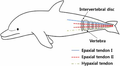
Figure 2. Concept of robotic dolphin adopted from anatomy of dolphin (modified and redrawn, (Sun et al 2010)).
Download figure:
Standard image High-resolution imageThe design of a VaSF device is implemented in a peduncle, as shown in figure 3. The entire shape of the peduncle is similar to that of a dolphin. Six rigid plates are used as backbones, with specific intervals between them. Four tendons are installed: two for driving and two for changing the stiffness. In figure 3, a dashed line shows a tendon for changing the stiffness, which is attached to the last rigid plate. The two solid lines show the tendons for driving, which are attached to the second rigid plate. As described earlier, the tendons for driving act as epaxial tendon I and the hypaxial tendon of a dolphin, which is attached to the vertebrae at the tip of the tail, whereas the tendons for changing the stiffness act as epaxial tendon II, which are inserted into the tip vertebrae. Furthermore, we consider the coupling between the tendons for driving and the tendons for changing the stiffness. When the stiffness tendons are pulled, the peduncle structure shrinks. Because of the shrinkage of the peduncle, the driving tendons become loose, and the VaSF device cannot be stabilized. To solve this issue, we installed a tension spring between the first rigid plate and the second rigid plate. A tension spring with a zero pitch angle is used, which has no space between adjacent single coils, so that the initial length of the spring does not decrease in the longitudinal direction but can easily bend transversally. Therefore, the shrinkage effect of the stiffness tendons is decoupled from the motion of the driving tendons. The weight balance of the VaSF device is also an important factor. If the peduncle of the robotic dolphin is much heavier than its head, the robotic dolphin cannot maintain a horizontal posture. To balance the robotic dolphin in the water, the weight of the VaSF device should be reduced. Therefore, air holes are needed inside the peduncle to reduce the weight of the VaSF device, as shown in figure 3. The VaSF device has the same density of water and the gravity or buoyancy of the peduncle has a little effect on dynamics of the fin. These air holes also reduce the stiffness of the VaSF device. The stiffness of the VaSF device is determined to the effective bending stiffness of the bonded cylindrical layer (EI). When the peduncle with air holes is built, the area moment of inertia is decreased. Therefore, the effective bending stiffness of the structure is decreased.
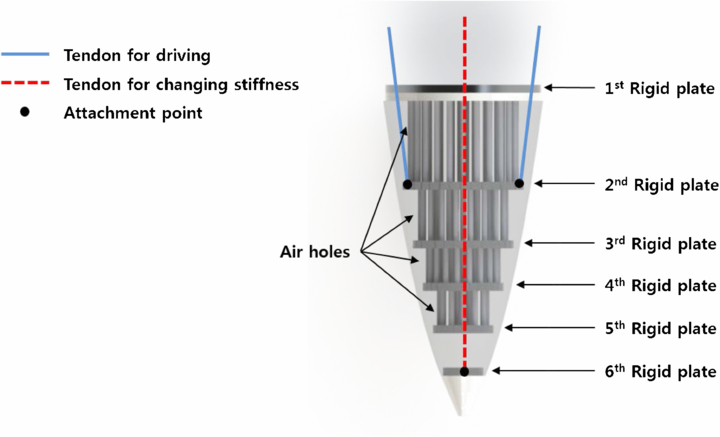
Figure 3. Design of driving part with variable-stiffness structure and tendons (red dashed line: tendon for changing stiffness, blue solid lines: tendons for driving, dots: attachment points).
Download figure:
Standard image High-resolution imageTwo servomotors pull the tendons, as shown in figure 4. The one for driving (Robotis Dynamixel MX-106) generates a sinusoidal motion to produce the thrust of the flapping device. When the servomotor oscillates as a sinusoidal function, one tendon pulls the VaSF structure and the other tendon releases it alternately. The other (Robotis Dynamixel MX-28) rotates and winds the tendon to increase the stiffness of the flapping device. Pulleys are used to guide the tendons.
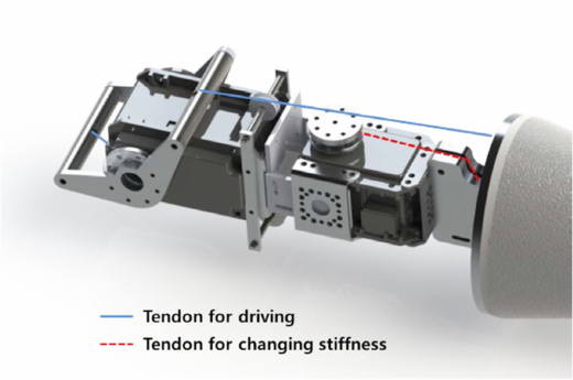
Figure 4. Design of driving parts with two servomotors (red dashed line: tendon for changing stiffness, blue solid line: tendon for driving).
Download figure:
Standard image High-resolution image2.2. Simple model of the VaSF mechanism
A PRBM is used to analyze the amount of stiffness variation from the most flexible case to the stiffest case. The PRBM is adopted because the bending behavior of the VaSF mechanism is considered to be a large deflection (Howell 2001). Figure 5 shows the PRBM of the VaSF mechanism, which consists of six rigid segments, along with a fixed end and five compliant segments. Each segment has a circular cross section. Although the thicknesses of the rigid segments are the same, the thicknesses of the compliant segments are different. Because the thicknesses and radii of the compliant segments are different, the values of the pseudo torsional spring constant Ki for the compliant segments are also different. The variation in the bending stiffness can be expressed as


where (EI)' is the effective bending stiffness of the bonded cylindrical layer; E is Young's modulus for the flexible material; I is the area moment of inertia; G is the shear modulus of the flexible material; S is the shape factor, which represents the shape change caused by the compressive force; R is the cylindrical radius of the compliant segment; and l is the compressed length of the compliant segment. When the compliant segment is compressed, the shape factor and effective stiffness increase. However, as mentioned in the previous section, the tension spring with a zero pitch angle was installed in the first compliant segment to decouple the shrinkage effect of the stiffness tendons from the motion of the driving tendons. Therefore, the shape factor and effective stiffness of the first compliant segment do not change because it is not compressed. It means that the length of the first compliant segment is constant. In addition, the torsional stiffness of the tension spring should be considered. The torsional stiffness constant of the first compliant segment is several hundred times larger than that of the tension spring. Therefore, there is little effect of spring to vary the stiffness of the VaSF structure. Even though the effect of tension spring is small, the torsional spring constant was considered in order to improve the model. To simplify the model, we assume that Young's modulus is constant, and the rigid segment is assumed to be perfectly rigid. The stiffness of the VaSF device can be calculated using the ratio of the end-tip load to the end-tip deflection. We assume that the force at the end point is applied in the vertical direction, even though the direction of the force varies relatively, depending on the deflection of the peduncle and fluke. Therefore, we apply a pure vertical loading condition on the last rigid segment (the sixth rigid segment). The characteristic radius factor of a pure vertical loading condition, γb, is equal to 0.8517; the parametric angle coefficient of a pure vertical loading condition, cθb, is 1.2385; and pseudo torsional spring constant K5 is

We assume that the other segments are under a pure bending moment condition. The characteristic radius factor of an end-moment loading condition, γm, is equal to 0.7346; the parametric angle coefficient of an end-moment loading condition, cθm, is 1.5164; and the other pseudo torsional spring constants K1, K2, K3 and K4 are
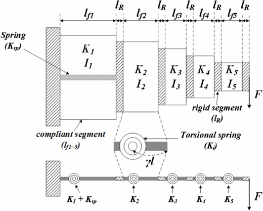
Figure 5. PRBM of the VaSF mechanism.
Download figure:
Standard image High-resolution imageThe total torsional spring constant of the first compliant segment is

where Kfirst is the total torsional spring constant of the first compliant segment; and Ksp is the torsional spring constant of the spring.
The length of each PRBM segment is described as
where lfi is the length of the ith compliant segment; and lR is the length of the rigid segment. The bending moment equilibrium is calculated as
where θi is the deflection angle of the ith compliant segment; and F is the load on the end-tip of the structure in the vertical direction. Because of the loading condition, the bending moment equilibrium of the fifth segment is different from the others. The fifth segment is under a pure vertical loading condition, whereas the other segments are under pure bending moment conditions. Equation (7) is solved with a numerical method using MATLAB, and the angle of each segment is obtained. Using these results, the stiffness variation is estimated. Two kinds of silicone (EcoFlex 0010 and 0030: Smooth-On, Inc.) are used as compliant segments to evaluate the deflection of the structure. The result of the stiffness estimation is shown in figure 6. The VaSF device with EcoFlex 0030 has a stiffer structure than the VaSF with EcoFlex 0010. However, the overall stiffness of the VaSF device with EcoFlex 0030 is too stiff to apply to the flapping device of the robotic dolphin. Therefore, on the basis of this result, EcoFlex 0010 is chosen as the material for a flexible segment.
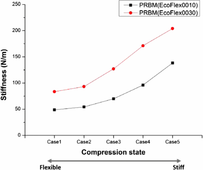
Figure 6. Stiffness estimation results for the VaSF device using the PRBM. The symbols '▪' and '•' represent the stiffness corresponding to EcoFlex 0010 and EcoFlex 0030, respectively. Case 1 is the most flexible condition, and case 5 is the stiffest condition.
Download figure:
Standard image High-resolution image3. Experimental setup of the VaSF device
The goal of the experiment was to measure the thrust of the VaSF device and evaluate its effectiveness by varying the stiffness. The experimental setup was similar to that used in the previous study, as shown in figure 7 (Park et al 2012, 2010). The driving system of the VaSF device for the experiment was set up on two force transducers above a water tank. It was mounted along the vertical direction, and the direction of movement, the same direction as the thrust generation, was upward. To reduce the effect of flow reflection, the depth of the water tank was kept five times the length of the fluke, and a sponge was attached to the wall of the water tank to absorb waves. Two force transducers (Ktoyo 333FB) were used to measure the thrust force. Using LabVIEW software installed on a National Instrument CompactRIO DAQ 9172, we measured and processed the force transducer data, which were recorded at 2000 samples per second. Before the thrust force was measured, the force transducer was recalibrated and set to zero. When the tendon for changing the stiffness was pulled, a load was applied to the force transducer and the force increased. Therefore, the force transducer had to be recalibrated when the stiffness of the VaSF device varied. Because the two force transducers were installed side by side, the overall thrust force was obtained by summing the two sets of force data. The bending movement of the peduncle and fluke was recorded using a Photron FASTCAM-APX RS high-speed camera at 1000 frames per second. The stiffness of the VaSF device was measured using a tensile tester, RampB Micro load RB302.
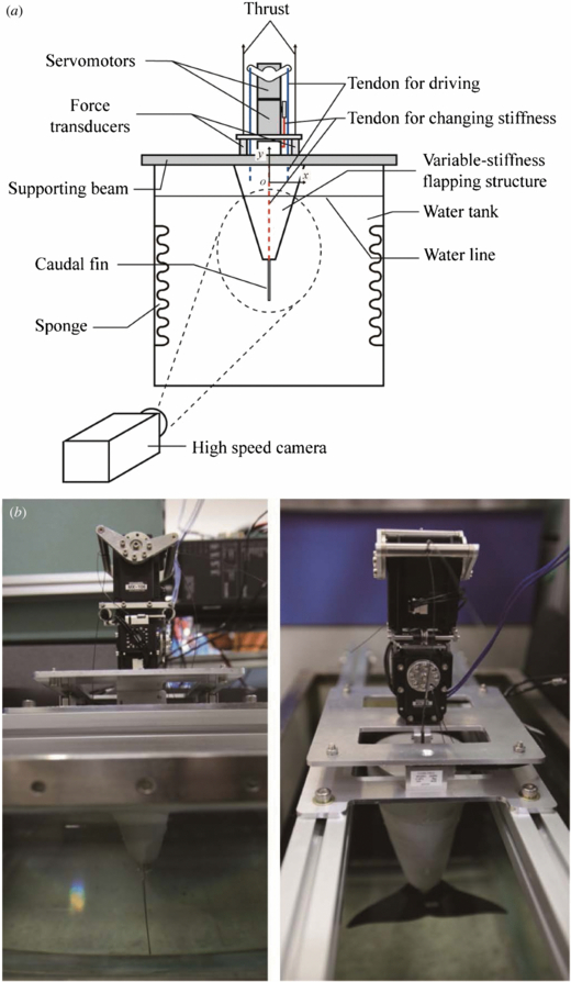
Figure 7. (a) Layout of experimental setup and variable-stiffness flapping structure with the caudal fin, (b) actual apparatus.
Download figure:
Standard image High-resolution imageThe parameters were determined to increase the dynamic performance of the robotic dolphin using the VaSF device. As listed in table 1, three parameters were considered: the amplitude; frequency, which ranged from 0.5 to 1.2 Hz; and the stiffness, which could actively vary. The amplitude was defined as the oscillating magnitude of the servomotor. The frequency was defined as the oscillating frequency of the servomotor. The amplitude and stiffness could be varied continuously by varying the rotating angle of the servomotors. However, using the discrete values of the amplitude and stiffness as parameters was sufficient to verify the effectiveness of the VaSF device. The experimental stiffness results obtained using the tensile tester are listed in table 1. Because the stiffness values were well distributed, the effect of the stiffness on the thrust generation could be properly evaluated. Finally, in this experiment, we considered two amplitude angles, five frequencies and five stiffness states.
Table 1. Control parameters of the VaSF device.
| Amplitude (°) | 20, 30 |
| Frequency (Hz) | 0.5, 0.6, 0.8, 1.0, 1.2 |
| Stiffness (Nm−1) | 48.0, 54.2, 78.8, 105.4, 155.9 |
4. Experimental results
The VaSF device is shown in figure 8. When the tendons for changing the stiffness are pulled, the stiffness of the VaSF device increases. The elastic material protrudes in the radial direction, as shown in figure 8(b), and the length of the peduncle decreases in the longitudinal direction.
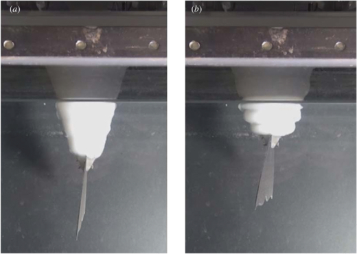
Figure 8. (a) Flexible state of peduncle and (b) stiff state of peduncle.
Download figure:
Standard image High-resolution imageThe thrust results using the VaSF device are shown in tables 2 and 3, which give the thrust results at amplitudes of ±20° and ±30°, respectively. The measured thrust was averaged over one period of oscillation. As the oscillating frequency increased, the thrust increased for all cases at a certain stiffness condition. However, as the stiffness increased, the thrust did not always increase for all cases at a certain frequency. In figures 9 and 10, the maximum thrust is shifted to a higher stiffness case as the oscillating frequency increases. When the oscillating frequency increases, the stiffness of the peduncle should increase to generate more thrust and to find the maximum thrust condition. The symbol '▾' represents the maximum thrust at a certain frequency condition. At low frequencies of 0.5 and 0.6 Hz, the flapping device that generates the maximum thrust is the second stiffness case, which is more flexible. At 1.2 Hz, the flapping device that generates the maximum thrust is the fourth stiffness case at an amplitude of ±20° and the fifth stiffness case at an amplitude of ±30°, which are much stiffer conditions than the low frequency condition. Hence, when the driving frequency of the flapping device increases, the stiffness of the peduncle that generates the maximum thrust increases. At a lower frequency range, a more flexible flapping device is better for maximizing the thrust. On the other hand, at a higher frequency range, a stiffer flapping device is better for increasing and maximizing the thrust. This phenomenon is also verified in nature. Swimming speed of fish can be controlled by changes in body flexural stiffness and the driving frequency. In order to swim faster, fish generate more thrust by stiffening the body (Mchenry et al 1995). Similarly, in order to swim at fast speeds, we should increase the operating frequency or change the stiffness to match the operating frequency. For a compliant peduncle to be optimal for multiple operating frequencies, the stiffness of the flapping device should be actively controllable. Therefore, the VaSF device is useful to improve the dynamic performance of a robotic dolphin under different operating conditions.
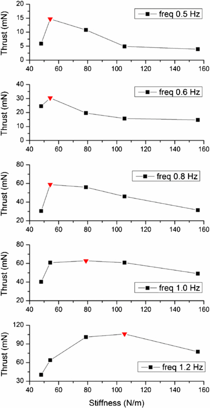
Figure 9. Thrust results with various frequencies and stiffnesses for peduncle at amplitude of 20°. The symbol '▾' represents the maximum thrust value at a certain frequency condition.
Download figure:
Standard image High-resolution image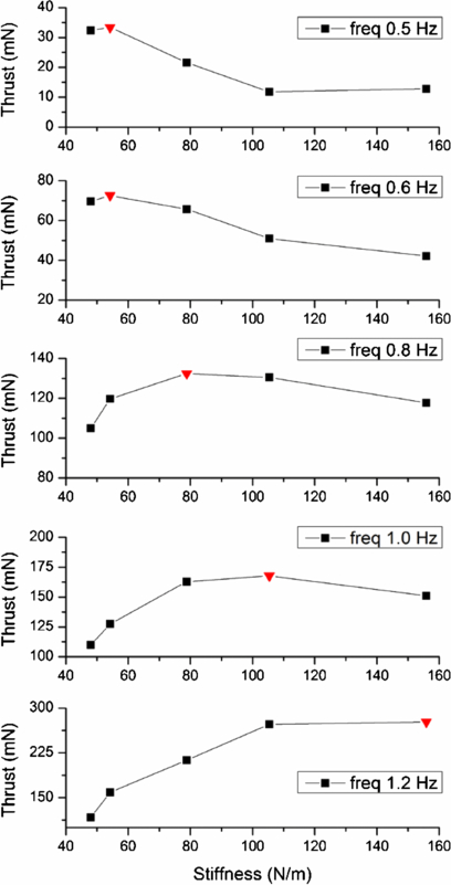
Figure 10. Thrust results with various frequencies and stiffnesses for peduncle at amplitude of 30°. The symbol '▾' represents the maximum thrust value at a certain frequency condition.
Download figure:
Standard image High-resolution image
Table 2. Thrust results at amplitude of 20° (mN).
| Stiffness (N m−1) | |||||
|---|---|---|---|---|---|
| Oscillating Freq (Hz) | 48.0 | 54.2 | 78.8 | 105.4 | 155.9 |
| 0.5 | 5.9 | 14.7 | 10.8 | 4.9 | 3.9 |
| 0.6 | 24.5 | 30.4 | 19.6 | 15.7 | 14.7 |
| 0.8 | 30.4 | 58.9 | 55.9 | 46.1 | 31.4 |
| 1.0 | 40.2 | 60.8 | 62.8 | 60.8 | 49.1 |
| 1.2 | 40.2 | 63.8 | 101.0 | 105.9 | 77.5 |
Table 3. Thrust results at amplitude of 30° (mN).
| Stiffness (N m−1) | |||||
|---|---|---|---|---|---|
| Oscillating Freq (Hz) | 48.0 | 54.2 | 78.8 | 105.4 | 155.9 |
| 0.5 | 32.4 | 33.4 | 21.6 | 11.8 | 12.8 |
| 0.6 | 69.7 | 72.6 | 65.7 | 51.0 | 42.2 |
| 0.8 | 105.0 | 119.7 | 132.4 | 130.5 | 117.7 |
| 1.0 | 109.9 | 127.5 | 162.8 | 167.8 | 151.1 |
| 1.2 | 116.7 | 158.9 | 212.9 | 272.7 | 276.6 |
When a robotic fish is driven at a certain frequency, its thrust can be increased by up to three times, depending on the stiffness of the peduncle, as described in tables 2 and 3. However, when the stiffness of the VaSF device increases, its length decreases, as shown in figure 8. If the length of the variable-stiffness structure is decreased, the thrust generally decreases. According to the experimental results, the thrust of the VaSF device at a higher stiffness case increased, even though the length of the driving device decreased. This means that the shrinkage effect on the thrust generation can be less than the effect of increasing the stiffness. Therefore, the VaSF device can be useful for improving the thrust of a robotic dolphin despite the shrinkage issue.
In previous research, we present a simple method to identify the condition for maximizing the thrust generated by a compliant fin propulsion system (Park et al 2012). To find the condition, particular kinematic parameters were defined; a driving angle which is defined as the operating angle, a fin-bending angle which is described as the actual tail beat amplitude, and a phase difference between the sinusoidal motion of the driving angle and the fin-bending angle. As a result, the maximum thrust is obtained when a compliance creates a phase difference of approximately π/2 at a certain undulation frequency. This is a half-pi phase delay condition. To check the maximum thrust using the half-pi phase delay condition, we performed a kinematic analysis by capturing and analyzing images of the peduncle and fluke with a high-speed camera. Image analysis software (Xcites's ProAnalyst) was used to analyze the high-speed videos and to extract the bending and driving angles, which were defined in previous research (Park et al 2012). This program provided data on the position, displacement, speed, angle, velocity etc. Using the automated tracking system in ProAnalyst, data on the bending angle of the peduncle and fluke were obtained frame by frame. Table 4 lists the analytical results of the phase difference at 1.0 Hz. According to the previous research, the maximum thrust occurs when the phase difference is close to π/2. Thus, the maximum thrust in this experiment could be found between the fourth stiffness case and the fifth stiffness case. Therefore, the VaSF device could attain its maximum thrust condition by actively varying the stiffness of the peduncle.
Table 4. Phase difference and average thrust at 1.0 Hz.
| Phase difference | ||||
|---|---|---|---|---|
| Measured stiffness (Nm−1) | Thrust (mN) | Degree | Radian | Feature |
| 48.0 | 109.9 | 139.2 | 0.77π | |
| 54.2 | 127.5 | 129.5 | 0.72π | |
| 78.8 | 162.8 | 120.3 | 0.67π | |
| 105.4 | 167.8 | 104.8 | 0.58π | Thrust max |
| 155.9 | 151.1 | 65.3 | 0.36π | |
Thus, the bio-inspired underwater robot can generate more thrust using a controllable stiffness mechanism. The optimum stiffness to maximize the thrust could be found by applying a trial-and-error procedure using flukes with different stiffness values. On the other hand, the VaSF device is a simple mechanism to actively change the stiffness. Even though this device also requires the application of a trial-and-error procedure, it can be used as a feasible device to drastically reduce the number of experiments. The details on how to apply the results to define an optimum stiffness condition for the flapping device are as follows. The procedure is similar to that used in the previous research (Park et al 2012). First, we determine the oscillating frequency and amplitude parameters, which are related to the operating condition and motor specifications, respectively. Then, the speed or thrust of the bio-inspired underwater robot is measured to find the maximum value as the stiffness of the device is gradually increased. When the speed or thrust of the bio-inspired underwater robot reaches the maximum, this is the optimum stiffness condition to maximize the thrust.
5. Conclusion
In this paper, we presented a variable-stiffness flapping (VaSF) device that uses a bio-inspired variable-stiffness mechanism to improve the dynamic performance of a bio-inspired underwater robot. The VaSF mechanism was inspired by the endoskeleton structure, especially the vertebral column. The anatomy of the fluke of a dolphin was considered to determine the attachment points of the tendons. This VaSF mechanism can be applied to a horizontal flapping tail or a vertical flapping tail because it adopted an endoskeleton structure. It was fabricated by bonding alternating rigid segments and compliant segments in series. When each compliant segment is compressed, the effective bending stiffness of the elastic material increases, and the entire structure is stiffened. On the basis of this mechanism, a compact and scalable VaSF mechanism was built. A PRBM was used to analyze the amount of stiffness variation from the most flexible condition to the stiffest condition.
The effectiveness of the VaSF device was verified by measuring the thrust under different operating conditions. The results showed that when the oscillating frequency of the flapping device changes, the maximum thrust is achieved by changing the stiffness of the peduncle. The maximum thrust is generated by increasing the stiffness of the flapping mechanism as the oscillating frequency increases. Hence, when the driving frequency of the flapping device increases, the stiffness of the peduncle that generates the maximum thrust increases. This result has also been verified in biology (Mchenry et al 1995). The maximum thrust case was verified using the half-pi phase delay condition, which was described in previous research (Park et al 2012).
Further research on a control method using various sensors could enable the development of a bio-inspired underwater robot that adjusts the stiffness of the fin according to the operating conditions in real time. Depending on the driving conditions such as the oscillating frequency and the amplitude of the flapping device, the stiffness of the flapping device can be optimized. If the efficiency of the VaSF mechanism can be improved, it can prove to be an important step forward in the research on bio-inspired robots.
Acknowledgments
This research was supported by the Converging Research Center Program, the Basic Science Research Program, and the Priority Research Centers Program through the National Research Foundation of Korea (NRF) funded by the Ministry of Education, (2009-0082824, 2009-0087640, and 2011-0030744). The authors would like to thank Hyunki In for constructive comments.