

Abstract
Most robotic applications that contain shape memory alloy (SMA) actuators use the SMA in a linear or spring shape. In contrast, a novel robotic finger was designed in this paper using SMA plates that were thermomechanically trained to take the shape of a flexed human finger when Joule heated. This flexor actuator was placed in parallel with an extensor actuator that was designed to straighten when Joule heated. Thus, alternately heating and cooling the flexor and extensor actuators caused the finger to flex and extend. Three different NiTi based SMA plates were evaluated for their ability to apply forces to a rigid and compliant object. The best of these three SMAs was able to apply a maximum fingertip force of 9.01N on average. A 3D CAD model of a human finger was used to create a solid model for the mold of the finger covering skin. Using a 3D printer, inner and outer molds were fabricated to house the actuators and a position sensor, which were assembled using a multi-stage casting process. Next, a nonlinear antagonistic controller was developed using an outer position control loop with two inner MOSFET current control loops. Sine and square wave tracking experiments demonstrated minimal errors within the operational bounds of the finger. The ability of the finger to recover from unexpected disturbances was also shown along with the frequency response up to 7 rad s−1. The closed loop bandwidth of the system was 6.4 rad s−1 when operated intermittently and 1.8 rad s−1 when operated continuously.
Export citation and abstract BibTeX RIS
1. Introduction
Due to their light weight, shape memory alloy (SMA) actuators offer tremendous advantages over traditional motors [1, 2]. SMA has been used in a variety of robotics applications such as with micromanipulators [3], pumps [4], bioinspired inchworms [5], biomimetic fish [6], and robotic octopi [7]. SMA actuators have been incorporated into robotic hands as well [8, 9]. Several groups have used SMA wires attached across the joints of the fingers [10]. In this manner, heating the SMA wire results in flexion or extension of that particular joint [11]. This has also been done with finger tendon drive systems using SMA wires in series with linear springs [12] or through segmented binary control [13]. SMA actuators have also been used in conjunction with dc motors for hybrid actuation of an artificial finger [14] and a surgical manipulator [15]. Other groups have investigated the use of SMA springs to actuate artificial grippers [16, 17].
Despite their advantages, SMA actuators are well-known for their nonlinear behavior including hysteresis [18, 19]. For this reason, nonlinear methods such as sliding mode control [20], neural networks [21], and iterative learning techniques [22] are often used to control SMA actuators. During the heating phase, SMA actuators typically have a fast response time [23]. However, one problem with the application of SMA to robotic hands is that SMA requires a lengthy amount of time to cool down and return to its initial state [10, 24], even with forced air convection [17]. This low bandwidth limits the utility of SMA as an actuator in several areas, such as with prosthetic limbs [1, 25]. To address this problem in the past, a differential pulley system has been presented using antagonistic SMA wires [26]. In this situation, opposing SMA wires are used to drive the joint in either direction, which increases the speed of the system in comparison to approaches that use a spring return mechanism [27]. There have been many efforts to more rapidly cool SMA actuators, including solid heat sinks, heat conductive grease, oil immersion, and glycol mixed with water [42]. This water based cooling method enables the SMA to cool 100 times quicker than normal, which enables a higher actuation bandwidth.
Thus, underwater robotics could potentially be a good application for SMA actuators since the environment would naturally immerse the SMA in a rapid-cooling medium. Underwater grasping has been explored with autonomous underwater vehicles in the past for deep-sea exploration [28], salvage operations [29], and could potentially be used in search and rescue missions as well. However, the prior work in underwater grasping typically involves hydraulic or motor driven actuators [28].
Most SMA-actuated hands in the past have used an SMA wire or SMA spring to actuate a revolute joint [8, 10, 12–17, 26, 27]. Several other researchers have investigated out of plane actuation concepts using SMA as a bending beam or as a smart soft composite for coupled bend-twist movements [43–46]. In contrast, a novel contribution of this paper is the development of a thermal training technique for SMA plates to take the shape of a flexed human finger when Joule heated. This flexor actuator was arranged antagonistically with an extensor actuator that was designed to straighten when Joule heated. Thus, alternately heating and cooling the extensor and flexor actuators caused the finger to extend and flex. Three different SMA plates were evaluated for their ability to apply forces with a rigid and a compliant object. Next, a 3D CAD model of a human finger was used to 3D print a finger mold. Using a multi-stage casting process, the antagonistic SMA actuators and a position sensor were integrated into the artificial finger, which was Joule heated and water cooled. A nonlinear antagonistic controller was developed with a proportional-integral-derivative (PID) outer position control loop and two embedded current control loops. While underwater, the ability of the finger to track sine and square waves with different amplitudes and frequencies was assessed along with its ability to recover from unexpected disturbances. Finally, the frequency response of the finger was experimentally evaluated, from which the bandwidth was determined. Through these experiments, the upper bound of operational frequencies of the novel finger was demonstrated along with the operational ranges where excellent tracking can be expected.
2. Anthropomorphic finger design
2.1. Antagonistic actuator concept
The robotic finger uses two antagonistic SMA plate actuators in parallel (figure 1). The extensor actuator takes a straight shape when heated, whereas the flexor actuator is thermally trained to take a shape similar to the phalanges in the finger when heated. Initially, when both actuators are cool, the finger is in a natural posture (figure 1(a)). However, when the flexor actuator is Joule heated above the phase transition temperature, it forces the finger to flex (figure 1(b)). The extensor actuator can be subsequently Joule heated to force the finger to extend (figure 1(c)). Note that the flexor actuator is placed dorsally from the extensor actuator to minimize the backlash between the two actuators. For example, if the flexor was placed on the palmar side of the extensor, an actuator dead zone would result; the motion of the flexor actuator would be larger than the motion of the finger due to the compliance of the surrounding material.
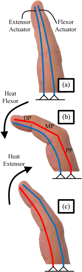
Figure 1. The antagonistic SMA plate actuator concept. (a) Initially, both SMA actuators are cool. (b) As the flexor actuator is heated while the extensor is cool, the finger flexes. (c) As the extensor is heated while the flexor is cooled, the finger extends.
Download figure:
Standard image High-resolution imageThis antagonistic actuation concept allows a more rapid motion in flexion and extension than would be permitted with the aforementioned spring return mechanisms that have been used with SMA actuators in the past. It also enables force to be actively applied in both directions of actuation. Biasing elements or spring return mechanisms allow application of active forces in only one direction.
2.2. SMA materials
Three different NiTi based SMA actuators were evaluated in this paper. Two of these polycrystalline NiTi plates had a thickness of 1 mm and were purchased from Memry (Weil am Rhein, Germany). The first plate, hereafter referred to as NiTi1 had a Ni50.1Ti49.9 atomic weight composition while the second plate, NiTi2, had a nominal Ni49.78Ti50.22 atomic weight composition. Also, a 1 mm thick polycrystalline ternary NiTiCu sheet was purchased from Kellogg's Research Labs (Moultonborough, USA) with a nominal Ni50Ti40Cu10 atomic weight composition. All of the SMA plates are in the martensitic phase at room temperature. Their shape memory effects are related to martensitic phase transformations. Upon Joule heating, a reverse phase transformation occurs in the plates from the martensite to the austenite phase. The austenite and martensite start and finish temperatures (AS, AF, MS, MF, respectively) for each of these alloys is listed in table 1. These phase transition temperatures were obtained via a Q10 differential scanning calorimetry machine (TA Instruments, New Castle, USA), figure 2(e). In this study, 30% cold rolled shape memory plates were used during the experiments. Since the required percentage of the cold work was already done, further prestrain was not applied before starting the experimental phase.
Table 1. Material properties and results from thermal shape training and the max force/compliant object experiments.
| Angles (rad), (figure 7(a)) | Max force, (figure 8(a)) | Compliant object (figure 8(b)) | |||||||||
|---|---|---|---|---|---|---|---|---|---|---|---|
| Material composition | MF temp | MS temp | AS temp | AF temp | ӨMCP | ӨPIP | ӨDIP | (N) | (N) | (mm) | |
| NiTi1 | Ni50.1 Ti49.9 | 28.6 °C | 48.8 °C | 51.5°C | 70.6 °C | 1.26 | 1.31 | 1.08 | 9.01 ± 0.19 | 1.85 ± 0.02 | 11.29 ± 0.21 |
| NiTi2 | Ni49.78Ti50.22 | 14.4 °C | 70.3 °C | 105.6°C | 116.4 °C | 0.66 | 1.19 | 0.98 | 5.82 ± 0.66 | 1.28 ± 0.02 | 7.80 ± 0.58 |
| NiTiCu | Ni50Ti40Cu10 | 25.5 °C | 51 °C | 62.4 °C | 92 °C | 0.63 | 1.15 | 0.94 | 5.46 ± 0.48 | 0.74 ± 0.05 | 3.03 ± 0.92 |
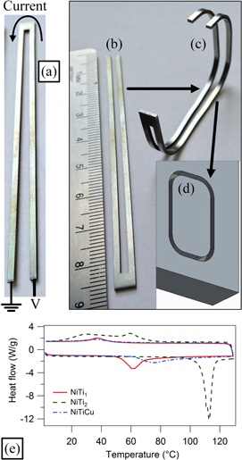
Figure 2. (a) Each SMA plate actuator was cut into the shape of a U to enable current flow. (b) Each actuator was 85 mm long, similar to human fingers. (c) The flexor actuators were bent into the rectangular shape and placed into the aluminum mold (d) to be thermally trained in a furnace. (e) The DSC results for the three different alloys showed different phase transition temperatures.
Download figure:
Standard image High-resolution image2.3. SMA actuators
Each SMA actuator was cut from a plate into the shape of a 'U' using an electric discharge machine. The U-shaped design permits electric current to flow through the SMA by connecting the two free ends to an electric power source at the base of the finger (figure 2(a)). The total length of each actuator was 85 mm with mass of 2 g (figure 2(b)).
Each flexor actuator was thermally trained to take the shape shown in figure 1(b) to enable the finger to flex. To that end, the SMA flexor actuators were bent into the shape shown in figure 2(c) and placed within the slot of an aluminum mold (figure 2(d)). The slot was machined into an aluminum plate with a CNC machine to have a depth of 5 mm and a channel width of 2.2 mm. Next, the aluminum plate containing the SMA flexor actuator was placed within a furnace (ST-1150C-458, Sentro Tech, Cleveland, USA) and heat treated for eight minutes at 600 °C. Afterwards, the plate and actuator were water quenched. This thermal training regimen enabled each flexor actuator to take the bent shape shown in figure 1(b) when Joule heated above its phase transition temperature.
Many robotic hands such as the Shadow Hand [30] and newer prosthetic hands like the i-Limb Ultra [31] make use of underactuated mechanisms [32], where the number of joints that rotate is greater than the number of actuators. In a sense, the thermal training of the flexor actuator results in an underactuated behavior also, where multiple segments of the actuator simultaneously rotate as a result of a single control input.
The lengths of the 'phalanges' of each flexor actuator were designed based on index finger measurements of human bones. The proximal phalanx was 39.02 mm, the middle phalanx was 23.03 mm, and the distal phalanx was 17.95 mm. Thus, the total length from the tip to the metacarpophalangeal (MCP) joint was 80 mm; 5 mm was allowed at the proximal base to connect the finger to the support (figures 1(b) and 2(c)). The relative ratio of the lengths of the SMA phalanges were scaled from the measured ratios of the lengths of human phalanges [33]. These SMA phalangeal lengths fall closely within the standard deviations of the corresponding human finger cadaveric measurements [33].
2.4. Finger fabrication process
The manufacturing steps to fabricate the biomimetic finger skin cover used in this paper began with surfacing the point cloud of an index finger (figure 3(a)) which was freely downloaded from Autodesk 123D (www.123dapp.com/123C-3D-Model/Finger-Index/866442) under the license for distribution (http://creativecommons.org/licenses/by-nc-sa/3.0/legalcode). Using SOLIDWORKS (Dassault Systèmes), the point cloud model was converted to a closed surface mesh model using the ScanTo3DFunction. Next, the knit function was used to create a solid model and grooves were added at the interphalangeal joints to increase the flexibility of the fabricated finger (figure 3(b)).
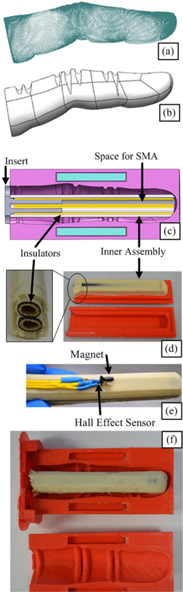
Figure 3. (a) A point cloud model of the finger was modified to create a solid model of a finger (b) in SolidWorks. (c) A dual mold system was developed with an inner part to house both SMA actuators and an outer part to house the position sensor and impart the finger-like shape. (d) The inner mold for the SMA actuators was 3D printed and the thermal insulators were incorporated in the rubber casing. (e) The Hall effect sensor and magnet were affixed to the outer surface of the inner part. (f) The inner assembly was placed in the outer mold of the finger to complete the design.
Download figure:
Standard image High-resolution imageA series of casting processes was used to make the finger from the solid model. Thus, the 'Combine' function was used to extract the finger model to form the required cavities to make the finger mold. An inner mold was also designed to house the SMA actuators while the outer mold was made to house the position sensor and the overall finger shape (figure 3(c)). Both molds were fabricated using PLA material in a 3D printing machine (Cube X Trio, 3D Systems). Pol-Ease 2450, (Polytek Development, Easton, USA) functioned as a release agent liquid to facilitate releasing the molded parts. Poly PT Flex 20 (Polytek Development) was used as the finger material. PT Flex 20 Liquid Rubber is a two-part molding rubber which offers a soft (Shore A ≈ 20), flexible, and fast-curing rubber.
Because each SMA actuator was to be Joule heated above 100 °C, two thermal/electrical insulators were embedded within the inner mold using T117EA4B thermal insulation tubing with an American Wire Gauge of 4 (Delfingen, Rochester Hills, USA), (figures 3(c) and (d)).These insulators prevented the finger skin material from melting when the SMA actuators were heated and also electrically isolated the actuators from each other. Additionally, the insulating tubes were left open at the base and tip to enable water to flow through and cool the actuators as the finger was flexed and extended underwater.
After 3D printing the inner and outer molds (figures 3(c) and (d)), the release agent liquid was applied to the 3D printed parts. The two components of the PT Flex 20 finger material were mixed together with a 1:1 ratio according to the manufacturer's data sheets using a high speed shear mixer (DAC 150, FlackTek, Landrum, USA). This machine helped to mix the two materials quickly since the Poly PT Flex 20 has a 5 min working time. It also helped to remove air bubbles trapped in the mixture during handling or mixing. Using the insert part (figure 3(c)), the two thermal insulator tubes were placed into the inner mold and the mixed finger rubber material was poured into the mold at room temperature. The inner part was ready and demolded after 90 min (figure 3(d)).
Next, an A1321 Hall effect position sensor (Allegro MicroSystems LLC, Worcester, USA) and magnetic bar were placed in their positions at the proximal interphalangeal (PIP) joint (figure 3(e)). Using another insert part, the inner assembly was placed into the outer mold (figure 3(f)) to complete the process using a similar fabrication method (figure 3(c)).
The resulting anthropomorphic finger was comparable in size, shape, and flexibility to a human index finger (figure 4). The fabricated finger including the Hall effect sensor and thermal insulators had a mass of 44 g.
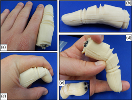
Figure 4. (a)–(d) The manufactured finger is comparable in size, shape, and flexibility as a human finger. (e) The ends of the thermal insulation tubes were open to the environment to enable water to flow through and cool the SMA actuators.
Download figure:
Standard image High-resolution imageSince the thrust of this paper is to develop a manipulator for undersea applications, the entrances to the thermal insulators at the fingertip were kept open to facilitate water flow inside the finger (figure 4(e)). This measure served to rapidly cool each actuator using the underwater environment, thereby increasing the bandwidth of the system. It was expected that as the finger would flex and extend, water from the environment would be forced through the inner cavity within each insulator to cool the actuators.
2.5. Electrical chassis
After fabricating the finger, an electrical chassis was designed to enable electric current to flow through each SMA actuator. Thus, a two-sided copper board was trimmed and etched. Each SMA actuator was connected to the copper board by 5 mm two-pin plug in screw terminal blocks.
Four aluminum connectors were also soldered on both sides of the copper board which were connected to the electrical power source via four 10 gauge wires. For protection, two rectangular ABS polymer blocks (4 cm × 2.6 cm × 1 cm) were cut and placed on both sides of the copper board. Two set screws were inserted into the ABS polymer blocks through the copper board to hold the board in place. The mass of the board and assembly was 81 g.
2.6. MOSFET current controller
A closed loop current control circuit was developed using an LM324 op-amp (Texas Instruments, Dallas, USA), (figure 5). Here, Vi is proportional to the desired current flow through the SMA ( corresponds to the extensor and flexor actuators, respectively.) The current flowing through the SMA (Ii) was measured with an ACS712 Hall effect sensor (Allegro MicroSystems), which was proportionally converted to a voltage and served as the feedback to the inverting input of the op-amp. The current flow through each SMA actuator was delivered by an NTE 2389 N channel MOSFET (NTE Electronics, Bloomfield, USA). A passive low pass filter was also used to attenuate any noise at the MOSFET gate. The current flow was limited at 20A, thus the power dissipated in each actuator was always between zero and 100 W.

Figure 5. The MOSFET current controller for each actuator is controlled by a voltage Vi from Simulink to drive current Ii through the extensor (E) and flexor (F) actuators (i ∈ E, F).
Download figure:
Standard image High-resolution image3. Antagonistic controller
SMA actuators are notoriously difficult to model accurately. Particularly so in this case because the actuators are Joule heated/water cooled and have been thermally trained to take the shape of a human finger. For this reason, a lumped parameters approach was taken to model the system:

TF and TE are the torques applied by the flexor and extensor SMA actuators, respectively. J, B, and K are respectively the effective inertia, damping and stiffness of the robotic finger system, which includes the skin, sensors, and environment or object in contact with the finger. Disturbances (D) can also be applied to the finger in an unpredictable way. Furthermore, the stiffness of the SMA actuators is subject to change as well when they are heated above their respective phase transition temperatures. X is the angular displacement of the finger. VF and VE are the voltage inputs to the MOSFET current controllers that Joule heat the flexor and extensor actuators (figure 5). GF and GE are the nonlinear relationships between the voltage inputs and the current outputs of the MOSFET controllers (IF and IE). MOSFET dynamics are nonlinear in general; furthermore, even with a constant desired current, the actual current delivered to each actuator can drift due to its change in impedance when significantly heated [26]. The MOSFETs subsequently Joule heat the flexor and extensor SMA actuators above their phase transition temperatures so they actuate and apply their respective torques (TF and TE) to the finger-environment system in opposite directions. Each actuator is both Joule heated and water cooled. The water cooling is not directly controlled, but rather occurs passively as the flexion and extension of the finger forces water to flow in and out of the insulating tubes that house each actuator of the finger. The nonlinear dynamics representing the relationships between Joule heating/water cooling the flexor and extensor actuators to the respective torques they apply are HF and HE.
Despite these highly variable system parameters and nonlinearities, excellent position tracking of the finger will be demonstrated through the nonlinear controller designed with two inner current control loops embedded within an outer nonlinear PID position feedback control loop (figure 6).

Figure 6. The nonlinear position controller with two embedded current control loops for the finger. The E and F subscripts are used for indicating the extensor and flexor actuators, respectively. There is a Hall effect sensor to supply current feedback for each MOSFET control loop to Joule heat both actuators.
Download figure:
Standard image High-resolution imageTo that end, the difference between the desired and measured finger postures is formed as

Next, an error manifold is formed as

In order to aggressively minimize the tracking error e, saturation functions are used to permit high gains without overheating and damaging the actuators. Through the designed thermomechanical training process (figure 2), the action of heating the flexor actuator will minimize positive errors while heating the extensor will minimize negative tracking errors because the actuators apply torques in opposing directions (figures 7(c)–(l)). Thus, VF and VE will never be active simultaneously. The control law for each actuator is defined by

and

which is graphically depicted in figure 6. The constant β was based on an upper bound estimate of the torques acting of the system model (1) and empirical observations concerning the maximum electrical current each actuator could reasonably tolerate. Taken together, these control laws resemble a sliding mode controller [30] with the exception that each actuator can only minimize positive or negative errors.

Figure 7. (a) The shape taken by NiTi1 after Joule heated by the current controller. (b) NiTiCu did not recover the thermally trained shape as well as NiTi1. A comparison between the trained shape and the human finger is also presented to illustrate the biomechanical basis for the thermal shape setting process. (c)–(f) The flexor actuator made from NiTi2 is Joule heated. (g) There was some relaxation of the material as it cooled. (h)–(l) The extensor actuator made from NiTi2 was manually bent into a curved shape and Joule heated to demonstrate the straightening action of the extensor. The time is also listed in each photo to show the speed of actuation.
Download figure:
Standard image High-resolution image4. Experimental methods
All control experiments were performed using MATLAB/Simulink (The MathWorks, Natick, USA) in conjunction with the real-time Windows target kernel. A PCI-6229 DAQ card (National Instruments) was connected to a BNC 2090 connector block, which served as the interface between the controller and the physical system. The sample rate of the controller was 1 kHz.
4.1. Evaluation of SMA materials
4.1.1. Flexor actuator posture
The thermomechanical training effects were evaluated for the flexor actuators with each of the three different actuators (NiTi1, NiTi2, NiTiCu) by sequentially placing each actuator in the electrical chassis, which was clamped to the bench top (figures 7(a) and (b)). Using only the current controller (figure 5), a step input of 19.4A was delivered to the actuator for three seconds with Simulink. A camera was also mounted in a fixed location to photograph the resulting posture of each actuator. The angles of the MCP, PIP, and distal interphalangeal (DIP) joints (ӨMCP, ӨPIP, and ӨDIP, respectively) were subsequently measured using the photos from the experiments (figure 7(a)).
4.1.2. Fingertip force and displacement evaluation
A manipulandum, which has been thoroughly described elsewhere [34], was used to assess the maximum fingertip force and displacement each actuator was capable of applying. Briefly, the manipulandum has an LSP-10 load cell (Transducer Techniques, Temecula, USA) to measure the applied force. This load cell is connected to a joint that can be locked when desired. There is an A1321 Hall effect sensor at the base of the manipulandum to measure the displacement when the joint is not locked.
Two sets of experiments were performed with the NiTi1, NiTi2, and NiTiCu actuators: max force and compliant object. First, the manipulandum and the finger were clamped to the bench top (figure 8(a)). In all cases, the fully assembled and fabricated finger was evaluated and the current controller (figure 5) was used to deliver a step input of 19.4A to the flexor actuator for three seconds. In the max force experiments, the manipulandum joint was locked and the maximum fingertip force of each of the three SMA materials was recorded. In the compliant object experiments, the manipulandum joint was free to rotate, but a compression spring with stiffness of 0.52 N mm−1 was placed between the two sides of the manipulandum to offer moderate resistance to the finger. In these experiments, both the displacement and force were recorded (figure 8(b)). Each experimental condition was repeated five times and the maximum forces and displacements were averaged and tabulated.
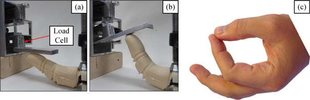
Figure 8. (a) The finger was placed under the manipulandum while it was locked to measure the maximum force each SMA actuator was capable of applying. (b) The manipulandum was subsequently unlocked and a spring was placed between the two sides to measure the force and displacement of the finger with a compliant object. (c) The posture of the human index finger when in a precision grip is comparable to the pose of the artificial finger.
Download figure:
Standard image High-resolution image4.2. Antagonistic controller evaluation
As will be subsequently shown, the NiTi1 alloy offered the greatest displacements and forces to be applied. Consequently, NiTi1 was selected for rigorous evaluation with the antagonistic controller in a series of square and sine wave tracking experiments. In all these experiments, the finger was completely submerged underwater in an aquarium.
4.2.1. Sinusoidal tracking experiments
In these experiments, the tracking ability of the controller with an external load was evaluated. Thus, the finger was depressed against the base of the aquarium and forced to repeatedly lift itself up and down with each cycle of oscillation (figures 9(a)–(e)). A comparison was made between three different amplitudes of desired sinusoidal inputs with peak-to-peak (p–p) amplitudes of 0.4, 0.7, and 1 rad. For each of these three amplitudes, frequencies of ω = 0.1, 0.2, 0.3, 0.6, and 0.8 rad s−1 were evaluated. The duration of each experiment was 90 s. The error, e (2), was measured in all cases and the average absolute error was calculated for each trial. A two factor analysis of variance (ANOVA) was performed to determine if the amplitude or frequency significantly impacted the average error.
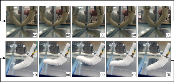
Figure 9. (a)–(e) The finger was placed in the corner of the aquarium and repetitiously forced to sinusoidally lift itself up and down. (f)–(j) The finger was freely suspended in the water and allowed to repetitiously flex and extend with different sinusoid frequencies to ascertain the frequency response of the finger.
Download figure:
Standard image High-resolution imageTo demonstrate the ability of the controller to overcome externally applied disturbances, another sinusoidal experiment was subsequently performed with ω = 0.3 rad s−1 and a p–p amplitude of 1 rad. In this experiment, the finger was manually pressed against the wall of the aquarium three times during the experiment with sufficient force to cause noticeable deviations from the desired position trajectory.
4.2.2. Square wave tracking experiments
In these experiments, the square wave tracking ability of the finger was evaluated while lifting an ABS plastic block (figure 10). Square waves with amplitudes of 0.5, 0.75, and 1 rad were each evaluated with five different frequencies: 0.083, 0.1, 0.125, 0.167, and 0.25 Hz. Each experiment was run for 90 s. The average tracking error per cycle was calculated and a two-factor ANOVA was also performed on the mean absolute error per cycle from the square wave tracking experiments.

Figure 10. (a)–(d) A top view of the block-lifting experiment is displayed from the perspective of a camera from outside the tank. (e)–(h) A lower view of the finger lowering the block is shown from the perspective of the underwater camera. This sequence was repeated for 90 s during each of the square wave tracking experiments.
Download figure:
Standard image High-resolution image4.2.3. Frequency response
The closed loop bandwidth was experimentally measured from the frequency response of the system. In this case, the finger was suspended freely in the aquarium and allowed to repetitiously flex and extend without any external contact with other objects (figures 9(f)–(j)). A sinusoidal desired posture trajectory with a p–p amplitude of 0.4 rad was input to the antagonistic controller with increasing frequency from 0.1 to 7 rad s−1. The amplitude ratio of the input and output sinusoids was calculated in decibels and the phase lag between the input and output posture was calculated in radians.
Two different characteristic behaviors emerged from these experiments with high frequencies of operation: at the beginning of the sinusoidal tracking, the system responded very quickly, which would be the case if the finger was operated intermittently. However, after several cycles of oscillation, the amplitude ratio decreased substantially and the phase lag increased, which would be the case if the finger was operated continuously. Thus, the amplitude ratio and phase lag were calculated for the intermittent and continuous operation modes. The intermittent mode frequency response was calculated using the mean of the first two cycles of oscillation for each frequency and the continuous mode frequency response was calculated using the last two cycles. Due to the speed of oscillation with higher frequencies, there was insufficient time to cool the actuators after several cycles of operation.
5. Results
5.1. Joint angles of flexor actuators
The NiTi1 alloy was able to recover its trained shape more accurately than the NiTi2 and NiTiCu alloys. A perfect recovery of the trained shape for the flexor actuators would have yielded ӨMCP = ӨPIP = ӨDIP = π/2 (and also resulted in a seldom used finger posture to make a fist). However, on average, heating NiTi1 produced ӨMCP = 1.26 rad, ӨPIP = 1.31 rad, and ӨDIP = 1.08 rad. These angles were larger in general than those obtained with NiTi2 and NitiCu, particularly with ӨMCP (table 1). The result of a typical heating cycle of the NiTi1 flexor in comparison to NiTiCu is shown in figure 7, which also illustrates the ability of NiTi1 to recover its trained shape more completely than NiTiCu. Also shown in figure 7(b) is a comparison between the flexor actuator and a human index finger, which shows the biomechanical basis for the trained shape. The flexing motion of a NiTi2 actuator is shown frame by frame in figures 7(c)–(f). As the actuator cooled, the material relaxed slightly (figure 7(g)).
5.2. Fingertip force and displacement
The max force experiments (figure 8(a)) showed that NiTi1 was consistently able to apply a larger fingertip force than NiTi2 and NiTiCu (figure 11(a)) in response to the same 3 s step input of current (figure 11(b)). On average, NiTi1 applied a fingertip force of 9.01N while NiTi2 and NiTiCu applied 5.82N and 5.46N, respectively (table 1). The current controller very consistently delivered the desired 19.4A of current to each actuator; however, because the impedance of the SMA changed as it was substantially heated [26], there was a small amount of drift in the current (figure 11(c)). This drift amounted to 0.49% of the 19.4A, or 0.1A, in each case. Because these experiments were done in air on the bench top, there was a lengthy amount of time for the SMA to cool and reduce the applied force (figure 11(a)). However, the rate of force reduction was comparable among all three SMAs.

Figure 11. (a) Maximum force data for the NiTi1, NiTi2, and NiTiCu plates. Five force responses are shown for each case. Note the fast response time of each plate; however, the cooling time is lengthy without water cooling. (b) A three second pulse of current was delivered to each SMA plate. (c) There was a small amount of drift in the current delivered to each plate even with a constant desired current (ID) because heating the SMA changed its electrical impedance. On average, the amount of drift in the current was 0.49%, or 0.1A.
Download figure:
Standard image High-resolution imageThe compliant object experiments (figure 8(b)) were performed to enable the finger to interact with a compliant object. Again, NiTi1 was able to apply a consistently larger force (figure 12(a)) due to a larger fingertip displacement (figure 12(b)). On average, the maximum force in this situation with NiTi1 was 1.85N while it was 1.28N and 0.74N with NiTi2 and NiTiCu, respectively (table 1). In all these experiments, there was a small amount of residual displacement at the end of the experiment due to the material stiffness of each actuator that the spring was unable to overcome.

Figure 12. (a) The measured fingertip forces and (b) displacements during the compliant object experiments shown in figure 8(b).
Download figure:
Standard image High-resolution image5.3. Sinusoidal tracking experiments
While the finger was submerged and forced to lift itself up and down with NiTi1 (figures 9(a)–(e)), the antagonistic controller enabled excellent position tracking results. Illustrative data from sinusoidal frequency ω = 0.3 rad s−1 with the 0.4, 0.7, and 1 rad p–p input amplitudes (figure 13, top) showed minimal tracking errors in each case, typically less than 0.04 rad (figure 13, bottom).

Figure 13. (Top) The desired (XD) and measured (X) sinusoidal posture of the finger for angular frequency of ω = 0.3 rad s−1. The preceding superscript in the legends indicates the peak-to-peak amplitude of the three different sets of sinusoids. (Bottom) The tracking error in these experiments was typically less than 0.04 rad in all cases.
Download figure:
Standard image High-resolution imageAs the input frequency increased to ω = 0.8 rad s−1, the tracking performance of the antagonistic controller was still excellent with the 0.4 rad amplitude input, but deteriorated with the larger input of 1 rad p–p. As a result of the water being unable to cool the actuators rapidly enough, the mean average error was noticeably larger with the high frequency, high amplitude sinusoids with respect to the other cases (figure 14(a)).

Figure 14. The average absolute error for the finger posture tracking experiments with three different amplitudes and five different frequencies of (a) sinusoids and (b) square waves.
Download figure:
Standard image High-resolution imageThese experiments demonstrated the reasonable range of continuous operation of the finger. Average tracking errors were decidedly small across all frequencies and amplitudes with the exception of 1 rad p–p sinusoid with frequencies of ω = 0.6 and 0.8 rad s−1 (figure 14(a)). Over the ranges tested, the two-factor ANOVA indicated that neither the amplitude nor the frequency significantly impacted the mean absolute error (p > 0.05).
The controller was also able to recover from the three manually applied disturbances (figure 15(a)). This was accomplished by the controller via saturating S to the maximum value as each disturbance was applied to minimize the error between XD and X (figure 15(b)).

Figure 15. (a) During this sinusoidal tracking experiment, three disturbances were applied by manually pressing the finger against the wall of the aquarium. The controller was able to recover from each disturbance. (b) The manifold S saturated to its maximum value as each disturbance was applied to overcome the unexpected tracking disruptions.
Download figure:
Standard image High-resolution image5.4. Square wave tracking experiments
The finger was also able to track the three different amplitudes of 0.083 Hz square waves well (figure 16). With the 0.5 rad p–p square wave, the response resembled a slightly underdamped system with minor overshoot. The response more closely resembled a critically damped system with the 0.75 rad amplitude input, which changed to a more overdamped response with the 1 rad amplitude square wave. The variations in system response characteristics are further illustrated for all three amplitudes with frequencies of f = 0.1, 0.125, and 0.167 Hz (figure 17). The experiment with 1 rad amplitude initially tracked the 0.167 Hz square wave well (figure 17(c)), but after the third cycle failed to reach the desired input amplitude of 1 rad. Results from f = 0.25 Hz (not pictured) resulted in poor tracking with all three square wave amplitudes. However, the mean absolute tracking errors for all three amplitudes and five frequencies are shown in figure 14(b); the errors generally increased with increasing input amplitude and frequency.

Figure 16. (Top) The square wave tracking for all three amplitudes with the 0.083 Hz frequency. The preceding superscripts in the legends indicate the three different peak-to-peak square wave amplitudes. (Bottom) S fully saturated at the rising and falling edges of each square wave cycle.
Download figure:
Standard image High-resolution image
Figure 17. The square wave tracking results with all three amplitudes with frequencies of (a) f = 0.1 Hz, (b) f = 0.125 Hz, and (c) f = 0.167 Hz. The preceding superscripts in the legend indicate the three different peak-to-peak square wave amplitudes.
Download figure:
Standard image High-resolution imageThe two-factor ANOVA on the mean absolute error from the square wave tracking experiments indicated that both the amplitude and frequency significantly impacted the error (p < 0.01).
5.5. Frequency response
In an intermittent operational mode (during the first two cycles of operation), there was minimal attenuation and phase lag up to ω = 2.25 rad s−1 (figure 18(a)). Even up to ω = 6 rad s−1 there was only 2.5 dB of attenuation during the first two cycles of the experiment (figure 18(b)). However, in the continuous operation mode, the attenuation and phase lag became more pronounced with lower input frequencies. The amplitude ratio (X/XD) and phase lag were measured up to ω = 7 rad s−1 for both the intermittent and continuous operation modes (figure 19). From the frequency responses, the closed loop bandwidth of the finger for intermittent use was found to be 6.4 rad s−1 (1.02 Hz) while it was 1.8 rad s−1 (0.29 Hz) in the case of continuous operation.
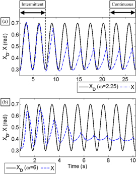
Figure 18. (a) The sinusoidal tracking response for ω = 2.25 rad s−1 was accurate during the first two cycles as would be the case with intermittent operation of the finger. However, with continuous operation, there was significant attenuation. (b) The tracking response for ω = 6 rad s−1 exhibited the similar characteristics during the first two (intermittent mode) and last two (continuous mode) cycles of operation.
Download figure:
Standard image High-resolution image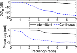
Figure 19. The frequency responses of the finger in the intermittent and continuous operation modes.
Download figure:
Standard image High-resolution image
6. Discussion
NiTi1 consistently recovered its thermomechanically trained shape better than NiTi2 and NiTiCu, enabling it to apply larger fingertip forces and displacements. This is likely due to the differences in atomic weight compositions of Nickel, Titanium, and Copper material blends, along with the different phase transition temperatures (figure 2(e), table 1).
In a statistical analysis of human finger joint angles during normal tasks of daily life, the maximum index finger angles from six test subjects was found to be 1.36 rad, 1.47 rad, and 1.03 rad for the MCP, PIP, and DIP joints [35]. These maximum human joint angles correspond quite closely to the artificial finger joints angles ӨMCP, ӨPIP, and ӨDIP with NiTi1 (table 1). However, due to the additional loads from the finger skin and the extensor actuator, the fully assembled artificial finger was not capable of bending as far as the flexor actuator was by itself (figures 7 and 9). Nevertheless, this also aligns well with more typical human index finger data which showed that for the majority of the time during tasks of daily life, the MCP joint was operated between 0 and π/3 rad with a mean angle of 0.56 rad. The human PIP primarily operated between 0.26 rad and π/3 rad with a mean angle of 0.59 rad, while the DIP mainly operated between 0 and π/6 rad with a mean angle of 0.26 rad [35]. These more typical human finger postures correspond closely to the posture obtained with the fully assembled finger, whose motion closely resembles that of a human index finger used in a precision grip with the thumb (figures 8(b) and (c)).
Human fingers are usually controlled synergistically to reduce the dimensionality of the control problem that would otherwise necessitate a high cognitive burden [36]. This is similar to how all joints of the artificial finger are driven by a single controller; however, the joint angle relationships could be altered by the grasped object or by the thermal training process (figure 2). During grasp operations with many different types of objects, human index fingertip trajectories tend to mainly reside on the periphery of the total available workspace [37]. The size of the grasped object affects how far the finger travels along the outside edge of the workspace [37, 38]. This same functionality is afforded by the design of the artificial finger and its posture controller (figure 9). However, additional dexterity could be enabled in the future by incorporating extra wires within the finger to selectively Joule heat certain segments of the SMA actuators.
Most SMA driven hands have increased the bandwidth of the system by using very thin diameter SMA wires [26, 27]. This is because the operational frequency of electrically heated SMA wires is inversely related to the wire diameter [39]. For example, the actuator bandwidth of an SMA driven hand has been reported as 0.2 Hz using SMA wires looped into an 'N' shaped configuration [27]. In contrast, the finger in this paper has a bandwidth of 1.02 Hz when operated intermittently or 0.29 Hz when continuously run (figure 19). The main difference in actuator bandwidth is likely due to the water cooling of the SMA plates used in this paper in comparison to thin diameter SMA wires.
A comparison between the bench top results with the actuator in air (figures 11 and 12) to the underwater experiments (figures 13–18) clearly showed that the water cooling greatly increased the operational speed of the finger (figure 19). Nevertheless, the water was unable to cool the SMA actuators rapidly enough with higher frequencies of operation, due to the heating effect of the water trapped inside the thermal insulator tubes. However, typical applications with the finger would not require it to be cyclically flexed and extended ceaselessly. Based on the frequency response (figure 19), the finger could be readily used to grasp and release an object in one second when operated intermittently (figure 18(b)). This is a more likely scenario for the intended application of underwater exploration, rescue, and salvage operations.
Nevertheless, due to its light weight, the finger could potentially be adapted for use as a prosthetic device similar to the SMA driven prosthetic hand in [27]. The increased bandwidth in this paper over the 0.2 Hz reported in [27] would come at the expense of extra mass from a self-contained fluidic system to cool the actuators, however. The mean maximum fingertip force with NiTi1 was 9.01N (table 1), which ranks in between the i-Limb and Bebionic prosthetic hands [31]. The power requirements for this SMA driven finger, if used for a prosthetic application, would be an important consideration, as in [27]. An important observation, however, is that many grasping motions require slow and delicate motions which would necessitate much less power use. Nevertheless, advancements in battery technology would be a welcome addition to the field of upper limb prosthetics [47].
In the future, thermocouples will be incorporated into the design of the finger to enable a thermal override setting to prevent unintentionally overheating the SMA actuators. Additionally, a compliant tactile sensor will be integrated into the finger for force control [40, 41].
7. Conclusion
A novel robotic finger antagonistically actuated by SMA plates was developed and evaluated while submerged in water. The flexor actuator was thermomechanically trained to take the shape of human index finger phalanges when Joule heated by the MOSFET current controller. A multi-stage casting process was developed to assemble the components of the robotic finger within the mold of a human finger. The antagonistic controller with an outer position feedback loop and an inner current control loop for each actuator was used in sine and square wave tracking experiments. The low tracking errors in conjunction with the system bandwidth of 6.4 rad s−1 (intermittent) and 1.8 rad s−1 (continuous) demonstrate that this manipulator could be successfully used in underwater applications such as deep sea exploration, rescue missions, and salvage operations.
Acknowledgements
This research was supported in part by the National Science Foundation award # 1265145.