

Abstract
In this research, carbon fiber reinforced polymer (CRFP) samples were milled at different cutting speeds and feed-rates. Milling of CFRP samples was performed using carbide cutting tools with TiAlN and TiN coatings which were deposited with physical vapor deposition (PVD) method. The effect of milling parameters on the surface roughness of the machined samples and resulting cutting forces was evaluated. The lowest average surface roughness was obtained with TiAlN coated cutting tools at 300 m min−1 cutting speed and 0.05 mm/tooth feed-rate. The highest average surface roughness was obtained with TiN coated cutting tool at 100 m min−1 cutting speed and 0.25 mm/tooth feed-rate. The lowest cutting force was obtained with TiAlN coated cutting tools at 300 m min−1 cutting speed and 0.05 mm/tooth feed-rate. The highest cutting force was obtained with TiN coated cutting tools at 100 m min−1 cutting speed and 0.25 mm/tooth feed-rate. Throughout the conducted tests, cutting tools with TiAlN coating were found to show superior machining performance over the others at different surface roughness and feed-rate machining parameters.
Export citation and abstract BibTeX RIS
1. Introduction
Composite materials have found wide usage in specific applications involving aviation and defense industries due to their superior properties such as high strength and low weight [1–3]. Carbon fiber reinforced polymers (CRFPs) from composite materials category exhibit outstanding fatigue strength, creep resistance and wear resistance with significantly low friction coefficient and high toughness. Recently, particular emphasis have been placed on manufacturing light and low-cost vehicles for fuel-saving purposes, which brought about an additional interest in the use of CFRP composites in these industries. Components made from CFRP composites exhibit superior mechanical and physical properties. As a result of their high strength, hardness, low weight, high rigidity and corrosion resistance, these materials have been preferred in various industrial applications [4]. They are widely used in space-aviation, automotive, defense and military applications due to their excellent strength/weight ratio [1–3].
After the production of CFRP composites in desired forms (via vacuum bagging, resin transfer molding, hand lay-up, etc), they are subjected to diverse machining processes (drilling, milling, turning) to obtain the final form. Among all machining processes applied on CFRPs, milling holds particular importance for acquisition of a good surface quality and dimensional precision. The surface quality obtained by milling process is significantly effective in the assembly of the produced components. Obtaining the desired tolerances and surface quality is highly dependent on the cutting parameters, tool geometry and cutting forces being used [5]. Determination of dimensional stability and interface quality by use of a suitable machining process also holds particular importance for obtaining a work-piece with the desired surface quality [6]. CFRP composites feature diverse fiber orientation angles and after being subjected to machining fiber directions are affected by cutting forces [7]. This is attributable to the fact that, the machinability of composites is dependent upon the machining direction [8] and wrong applications may result in serious and costly material failures. Rusinek (2010) reported that, increasing rotation speeds (rpm) result in reduced cutting forces and increasing feed-rates lead to an increase in cutting forces. Moreover, lower feed-rates were reported to have positive effects on tool life, machining times and costs. Sheikh-Ahmad et al (2012) reported that, in milling operations surface quality does not merely depend on the cutting parameters being used, but also on the fiber orientation angle. They also concluded that, the optimum surface quality in terms of surface roughness was obtained with lower feed-rates and higher cutting speeds [9]. Chen et al (2013), investigated the relationship between surface morphologies, cutting forces and tool geometries in down-milling of CFRP composites. In surface roughness evaluations, acceptable roughness values were achieved by use of double helix mill, however the roughness value of Ra = 3, 2 μm demanded for aviation applications was exceeded after using multi edge mill. Their findings also indicated that reduced feed-rate values were required for improved surface quality. They concluded that, the surface morphology was dependent on cutting parameters, a better surface quality was obtained with double helix mill, surface roughness increased with increasing feed-rate and decreased with increasing cutting speed [10]. Sorrentino and Turchetta (2014) reported that surface roughness values were reduced with increasing cutting speed. Their findings revealed that, increased cutting width and cutting speed yielded more better surface roughness values [11]. Wang et al (2015), modeled the relationship between the surface roughness and machining parameters in milling of CFRP composites using RSM method. During the tests, they observed an increase in surface roughness values with increasing feed-rates. Reportedly, increasing spindle speed resulted with impaired surface quality. Their findings showed that, feed-rate was one of the dominant factors that affect surface roughness in machining of composite materials [12].
Due to the anisotropic, inhomogeneous and abrasive structure of the CFRP composite material, deformations on cutting tool during machining take place and because of the deformations, damage to the material structure occurs and surface quality deteriorates. The problems that occur during the cutting process may cause fiber breakage and separation. In order to carry out the process efficiently and to obtain a smooth surface workpiece, dimensional stability and interface quality should be ensured by applying a correct machining process. The use of modern tool coatings improves the tribological behavior of the cutting tools for dry cutting processes. Contact surface properties and wear behavior of the cutting tool are improved by using cutting tool coatings instead of coolants. To improve the cutting performance and lifetime of carbide cutting tools, a hard coating surface can be obtained using the PVD method. Thanks to single and multi-layer conventional coatings such as TiN, TiAlN, TiCN etc, the lifetime and performance characteristics of the cutting tools are improved. In the present study, the relationship between surface roughness and cutting forces of TiAlN and TiN coated carbide cutting tools were examined in detail and the milling performances of TiAlN and TiN coated carbide cutting tools which were coated using PVD technique were compared. In this research, the cutting tools used in milling operations were used to machine the CFRP composite samples. Milling operations were performed on CFRP composite plate samples using three different cutting speeds, three different feed-rates and a constant cutting width. The effect of cutting speed and feed-rate on the resulting cutting force and the surface roughness of the work-piece were examined throughout the milling process. Research findings reveal that, TiAlN coated cutting tools exhibit superior machining performance at different surface roughness and machining conditions.
2. Experimental details
2.1. Test specimens
Due to the experimental investigations CFRP composite test samples with 140 × 100 × 6 mm dimensions were prepared and used in the tests (figure 1). The technical data are shown in table 1. 3 K and 2 × 2 twill weaves with tow (3000 filaments per fiber) fabric provides outstanding structural strength with a signature appearance that is highly desirable for modern composite parts. CFRP milling experiments are given in figure 2.

Figure 1. Illustration of workpiece material.
Download figure:
Standard image High-resolution imageTable 1. Material characteristics of the examined CFRP laminate.
| Weave type | Twill 2 × 2 |
|---|---|
| Fabric weight | 200 gr m−2 |
| Fiber volume content/fraction | 50% |
| Fiber orientation angle | (0°/45°/90°/−45°)s |
| Number of plies | 24 |
| Ply thickness in laminate | ∼0.2–0.3 mm |
| Resin type | Epoxy |
| Carbon fiber type | High tenacity (HT) |
| Number of filaments per roving | 3 K |
| Manufacturing Method | Vacuum bagging |

Figure 2. Details related to CFRP milling experiments.
Download figure:
Standard image High-resolution image2.2. Cutting tools and tool holder
TiAlN and TiN coated cemented carbide cutting tools, supplied from Sandvik Company, were used in the experimental studies. Removable cutting tips were specified as per ISO 1832 standard. The cutting tips (inserts) were positioned on the cutter in accordance with the ISO number of R390-025A25-11L standard. The tool holder has the cutting diameter of 25 mm and teeth number of 2. In this study, a single insert was mounted on the cutter during the milling tests for maintaining a constant cutting condition. Technical specifications of the PVD coated cutting tools are given in table 2. During the conducted tests, the used inserts were replaced with a new one for each machining operation. Accordingly, nine TiAlN coated inserts and nine TiN coated inserts were used during the tests.
Table 2. Technical specifications of cutting tools.
| No | Coated method | ISO code | Grade | Coated materials | |
|---|---|---|---|---|---|
|
1 | PVD | R390-11 T304E | NL H13A | TiAlN |
| 2 | PVD | R390-11 T304E | NL H13A | TiN |
2.3. Cutting parameters and design of experiment
The machining parameters applied in the tests were 100, 200 and 300 m min−1 as the cutting speeds which were specified in accordance with the recommendation of the manufacturer as per ISO 3685; 0.15, 0.15 and 0.25 mm/tooth as the feed-rates; and a constant radial cutting depth of 1 mm for all operations. Continuous machining was applied and no coolant was used during the machining operations. The parameters used in the experiments are shown in table 3.
Table 3. Machining parameters and conditions used during the milling experiment.
| Experiment number | |||
|---|---|---|---|
| 1–4–7 | 2–5–8 | 3–6–9 | |
| Cutting speed, Vc [m/min] | 100 | 200 | 300 |
| Feed rate, fz [mm/tooth] | 0.05–0.15–0.25 | 0.05–0.15–0.25 | 0.05–0.15–0.25 |
| Axial depth of cut, ap [mm] | 6 | 6 | 6 |
| Radial depth of cut, a.e. [mm] | 1 | 1 | 1 |
| Workpiece material | multi-directional CFRP plate | ||
| Lubricant | dry cutting | ||
Machining operations were performed on a 3-axis Falco VMC 850-B CNC vertical milling machine with 10 kW output. Cutting forces were measured with a dynamometer (Kistler 9257B) which was equipped with a multichannel amplifier (Kistler 5070) to obtain test data at 1000 Hz via a personal computer. The findings were then analyzed with Dyno Ware software. 140 mm cutting length was applied during cutting force measurements. Fx, Fy and Fz cutting force components were measured during the tests. Depending on the table speed, cutting force signals were recorded at varying periods for each machining test. The average of maximum cutting forces measured was calculated for each cutting force components. Following the measurement of cutting force measurements the resultant cutting force (FR) was evaluated using equation (1).

Surface roughness measurements were conducted using retractable type Mitutoyo Surftest SJ-310 surface roughness measuring equipment on the CRFP composite which was subjected to milling at 140 mm cutting length. The average of measurements from five different points on the machined surface was recorded.
3. Results
3.1. Surface roughness measurement
The average surface roughness values obtained after contour milling of the CFRP composite sample with TiAlN and TiN coated cutting tools using the specified machining parameters are shown in figures 3 and 4. The average surface roughness value of Ra = 3, 2 μm, recommended for space and aviation applications, was specified as the criterion for this research. In accordance with the specified limit surface roughness value, 2800 mm of the work-piece (corresponding to 20 passes) was removed from the composite sample.
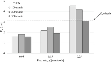
Figure 3. Average surface roughness results as a function of feed rates and cutting speeds for TiAlN coated inserts after 2800 mm for milling.
Download figure:
Standard image High-resolution image
Figure 4. Average surface roughness results as a function of feed rates and cutting speeds for TiN coated inserts after 2800 mm for milling.
Download figure:
Standard image High-resolution imageDuring the tests, the lowest average surface roughness value was determined as 1,58 μm with TiAlN coated cutting tool, and 181 μm with TiN coated cutting tool. The highest average surface roughness values during the machining operations were 5,37 μm with TiN coated cutting tool, and 454 μm with TiAlN coated cutting tool. During the milling of CFRP composite samples with coated cutting tools, average surface roughness values were found to increase with increasing feed-rates. Increased feed-rate had a negative effect on surface roughness and at 0.25 mm/tooth cutting condition the recommended surface roughness value for space and aviation applications was exceeded. The abrasive and heterogeneous structure of CFRP composite sample induced excessive cutting tool temperatures and the friction at the cutting tool/work-piece interface. Accordingly, increased average surface roughness values with increasing number of passes is attributable to the flank wear which arises from increasing cutting length and the resulting cutting edge radius [13, 14]. The average surface roughness values obtained after milling of CFRP composite samples with coated cutting tools decreased with increasing cutting speed. Thereby, an inverse correlation can be mentioned between cutting speed and average surface roughness. Increasing the cutting speed as a means for improving the average surface roughness is a widely mentioned method in the related literature. This mainly arises from facilitated removal of chips and reduced vibrations with increasing cutting speed, which in turn results in reduced average surface roughness [15–18]. The average surface roughness values obtained at high feed-rate (0.25 mm/tooth) and high cutting speed (300 m min−1) with both coated cutting tools were found to remain under the limit value for space and aviation applications. It can be accordingly concluded that, increasing the cutting speed leads to improved surface roughness which arises from facilitated cutting of fibers within the composite structure.
3.2. Cutting force measurement
The cutting force data obtained via dynamometer measurements during the contour milling of CFRP composite sample were recorded on a personal computer by use of an amplifier and the other data transfer elements. The average of the resultant cutting force (FR) was then interpreted. The resultant cutting force values obtained after the contour milling of CFRP composite samples with TiAlN and TiN coated cutting tools at the specified cutting parameters are shown in figures 5 and 6. The graphs of the resultant forces for the CFRP sample were plotted using the data obtained after 2800 mm chip removal.

Figure 5. Cutting force results as a function of cutting parameters for TiAlN coated inserts.
Download figure:
Standard image High-resolution image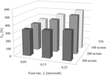
Figure 6. Cutting force results as a function of cutting parameters for TiN coated inserts.
Download figure:
Standard image High-resolution image
The resultant cutting force graph for the contour milling of CFRP sample with both cutting tools shows that, the lowest cutting forces are obtained at 300 m min−1 cutting speed and 0.05 mm/tooth feed-rate. As indicated in figures 5 and 6, increasing cutting speed results in a decrease in the resultant cutting force which is consistent with the literature findings [19–22]. In the obtained graphs, cutting forces increase with increasing feed-rate. The highest resultant cutting forces were observed as 515.05 N and 526 N respectively with TiAlN and TiN coated cutting tools at 0.25 mm/tooth feed-rate. The lowest resultant cutting forces were 342.48 N and 339.41 N respectively with TiAlN and TiN coated cutting tools at 0.05 mm/tooth feed-rate. During the milling of CFRP composite sample, the contact area between the cutting tool and work-piece increased with increasing feed-rate. Thus it can be inferred that, cutting forces increased with the increased amount of removed material [10]. The amount of removed material during the milling operation and fiber orientation angles also led to increased cutting forces [23].
Performance of coated tools varies depending on surface quality, cutting parameters, tool geometry and cutting forces. The wear resistance of the tools used in milling of CFRP composite material is directly related to surface quality. The reason why TiAlN coated cutting tools have higher performance characteristics than TiN coated cutting tools is that TiAlN coated cutting tools have higher hardness and adhesion strength. Previous studies about TiAlN and TiN coated cutting tools revealed that adhesion strength of TiAlN coated tools are mostly higher than TiN coated tools [24].
4. Conclusion
In this research, the effect of milling parameters on the machinability of CFRP composite samples machined with TiAlN and TiN coated cutting tools was evaluated. In this regard, the optimum cutting tool, cutting speed and feed-rate values were determined for contour milling of CFRP samples with PVD-coated cutting tools. Average surface roughness value, which is an important parameter in space and aviation industry, and cutting forces were collectively evaluated on the work-piece surface which was obtained after the performed contour milling operations. The obtained findings are as follows:
- The lowest average surface roughness values were obtained as 1.58 μm and 1.81 μm, respectively with TiAlN and TiN coated cutting tools. The highest average surface roughness values were obtained as 5.37 μm and 4.54 μm respectively with TiN and TiAlN coated cutting tools.
- The average surface roughness values of CFRP samples machined with TiAlN and TiN coated cutting tools increased with increasing feed-rate.
- The average surface roughness values of CFRP samples machined with TiAlN and TiN coated cutting tools decreased with increasing cutting speed, indicating a negative correlation between cutting speed and surface roughness.
- The lowest resultant forces were obtained at 300 m min−1 cutting speed and 0.05 mm/tooth feed-rate.
- The highest resultant cutting forces were obtained as 515.05 N with the TiAlN coated cutting tool and as 526 N with the TiN coated cutting tool at 0.25 mm/tooth feed-rate. The lowest resultant cutting forces were obtained as 342.48 N with the TiAlN coated cutting tool and as 339.41 N with the TiN coated cutting tool at 0.05 mm/tooth feed-rate.
- Resultant cutting force values decreased with increasing cutting speed. At low cutting speeds (200 m min−1), a 150% increase in the cutting speed resulted in 31.6% decrease in the resultant cutting force (370.81 N) with the TiAlN coated cutting tool, and 33.8% decrease (376.8 N) with the TiN coated cutting tool.
- TiAlN coated cutting tools were found to exhibit a superior performance at different surface roughness and feed-rate conditions.
Acknowledgments
This investigation was financially supported by Scientific Research Projects (BAP) of Bartin University (Grant Number: BAP.2016-FEN-C-004).