
Abstract
Cr3C2–NiCr+10%Ni/MoS2 composite coating was fabricated on H13 hot work mould steel using a Laser Thermal Spraying (LTS). The friction–wear behaviors of obtained coating at 25, 400 and 700 °C were investigated using a ball–on–disc wear tester, and the effect of MoS2 on the lubrication in the friction–wear process was also discussed. The results show that the average coefficients of friction (COFs) of Cr3C2–NiCr+10%Ni/MoS2 coating at 25, 400 and 700 °C are 0.68, 0.55, and 0.35, respectively, and the corresponding wear rates are 25.97 × 10⁻⁶, 30.06 × 10⁻⁶, and 11.86 × 10⁻⁶ mm3 · N–1 · s–1, respectively. The average COF and wear rate at 700 °C are the lowest among the three kinds of operation temperatures, the MoS2 particles and oxidation layer play a positive role of lubrication, which is the main factor of friction–wear reduction. The wear mechanism at 25 °C is abrasive wear, while those at 400 and 700 °C are primary abrasive wear, accompanied by oxidative wear.
Export citation and abstract BibTeX RIS

Original content from this work may be used under the terms of the Creative Commons Attribution 3.0 licence. Any further distribution of this work must maintain attribution to the author(s) and the title of the work, journal citation and DOI.
1. Introduction
Mould is the core equipment on manufacturing industry, accounted for more than 50% of formed parts [1, 2], which plays an important role in the fields of electronic power, transportation, aerospace and etc. Most wear occur on the mould surface [3–5], which has become the main mode of failure, therefore, surface coating technology is used to lengthen its service life. Compared with hard chromium plating, carburizing, nitriding, vapor deposition and other surface technologies, thermal spraying has the advantages of high efficiency [6, 7], which has been attracted attentions at China and abroad.
Coating technology is put forward to enhance the friction–wear performance [8, 9], NiCr coating with high wear resistance [10–12] is a hard coating, the additions of Cr3C2 and MoS2 [13–19] may improve the hardness and lubrication performances. Among them, Cr3C2 has the strongest anti–oxidation ability at high temperature, the fabricated coating has the advantages of strong bonding ability and uniform structure [20–22]; and MoS2 is used as a solid lubricant, which effectively reduces the Coefficient Of Friction (COF) [23–25].
Scholars investigated ceramic coating with lubrication properties through the compounding of spraying powder [26]. Yang et al [27] analyzed the structure and wear behavior of laser cladded NiCr/Cr3C2–WS2 composite coating, and found that the COFs were lower than those of non–WS2 coating. Wang et al [28] added MoS2 solid lubricant to WC–12Ni powder by electroless Ni–MoS2 co–deposition and revealed that the MoS2 particles was deposited with the Ni to form the Ni–MoS2 composite layer. Cao et al [29] prepared Cu/Cu–MoS2 self–lubricating coating by electrospark deposition, and showed that the self–lubricating coating had better wear resistance than the uncoated high–speed steel. And Sun et al [30] prepared the NiCr–Cr3C2–MoS2–CeO2 self–lubrication layer on 38CrMoAl extruder screw by laser processing, and found that the wear resistance was improved by supporting and connecting reinforced carbide phase and MoS2 lubricant. Despite the above researches on the NiCr and MoS2 coatings, the friction–wear performances of Cr3C2–NiCr coating with addition of MoS2 at high temperatures have rarely been reported, which become a hotspot of enhancing the service life of mould.
In this study, Cr3C2–NiCr+10%Ni/MoS2 coating was fabricated on H13 hot work mould steel using a Laser Thermal Spraying (LTS). The aim was to investigate the additions of Cr3C2 and MoS2 on the friction–wear performance of NiCr coating at high temperatures, which improved the functions of friction reduction and lubrication of hot work mould.
2. Experimental procedures
2.1. Sample preparations
The substrate was H13 hot work mould steel with the chemical composition (wt%): C 0.32–0.45, Si 0.80–1.20, Mn 0.20–0.50, Cr 4.75–5.50, Mo 1.10–1.75, V 0.80–1.20, P ≤0.03, S ≤0.03, and the rest was Fe. According to the ball milling experience and the quality of milled powder, the sprayed powders with the Cr3C2–NiCr and Ni–coated MoS2 mass frication of 90%:10% were mixed using a QM3SP04L type planetary ball miller for two hours, the required particle sizes were achieved, in which the Cr3C2 and NiCr powders accounted for 75 and 25%, respectively. The LTS process was performed on a ZKSX–2008 type fiber–coupled all–solid–state laser spraying system, Ar was used as the power source of powder feeding. Spraying parameters: spot diameter of 4 mm, laser power of 1500 W, laser focus distance of 250 mm, overlap ratio of 75%, spraying distance of 80 mm, powder feeding speed of 6 g · min–1, argon gas speed of 15 L · min–1, workbench speed of 8 g · min–1.
2.2. Characterization methods
The morphologies and chemical composition of obtained coating were analyzed using a JSM–6360LA type scanning electron microscopy (SEM) and energy dispersive spectrometer (EDS), respectively, and the phases were analyzed using a D/max2500 PC type x–ray diffraction (XRD).
The friction–wear test was performed on a HT–1000 type high temperature wear tester with the technological parameters: tribo–pair of Si3N4 ball with the diameter of 5 mm, load of 4 N, rotation speed of 500 r/min, rotation radius of 4 mm, respective temperature of 25, 400, and 700 °C, and operation time of 30 min.
After the wear test, the morphologies and chemical element distributions of worn tracks were analyzed using a SEM and EDS, respectively, and the profiles of worn tracks were measured using a VHX–700FC type ultra–depth–of–field three–dimensional microscope.
Wear rate was

where V was wear volume/mm3, i.e. 2π × Rotation radius × Area of worn track; S was total sliding distance/m; and F was load/N.
3. Analysis and discussion
3.1. Morphology and XRD analysis of powder
Figure 1(a) shows the morphologies of Cr3C2–NiCr+10% Ni/MoS2 powder. The powder was composed of spherical, lamellar and irregular long strip particles, which were uniformly distributed, with no agglomeration phenomena. Figure 1(b) shows the result of plane scan analysis on the Cr3C2–NiCr+10% Ni/MoS2 powder. The mass fractions of chemical elements (mass, %): Cr 43.81, C 3.98, Ni 33.29, Mo 14.95, S 3.20, Al 5 0.and W 0.28, among them, the Al and W were impurity elements. The Cr, C, Ni, Mo and S were enriched on the local zones, indicating that the Mo and S existed with the form of MoS2, as shown in figures 1(c)–(g).
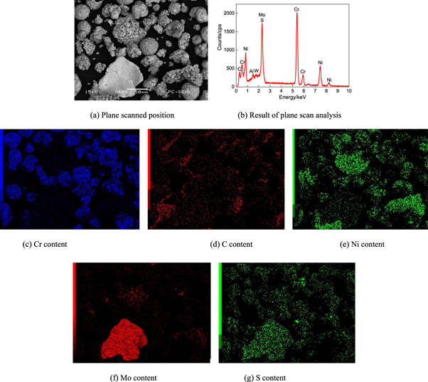
Figure 1. Plane scan analysis of Cr3C2–NiCr+10%Ni/MoS2 powder.
Download figure:
Standard image High-resolution image3.2. Morphologies, EDS and XRD analyses of coating
Figure 2(a) shows the morphology of Cr3C2–NiCr+10%Ni/MoS2 coating surface. The coating was composed of spherical particles, massive particles and unmelted MoS2 particles, with no other defects.

Figure 2. Morphologies, EDS and XRD analysis of Cr3C2–NiCr+10%Ni/MoS2 coating.
Download figure:
Standard image High-resolution imageFigure 2(b) shows the morphology of Cr3C2–NiCr+10% Ni/MoS2 coating cross–section. There was an obvious fusion line between the coating and the substrate, with no porosity.
Figure 2(c) shows the EDS analysis result of Cr3C2–NiCr+10% Ni/MoS2 coating. There were Mo and S on the marked A zone in figure 1(a), the atom ratio of Mo and S was close to 1:2.
Figure 2(d) shows the XRD patterns of Cr3C2–NiCr+10% Ni/MoS2 coating. The peak of CrxSy appeared on the coating, indicating that the Ni–coated MoS2 decomposed, which formed the compound of CrxSy with the Cr, i.e.,

Although the part of MoS2 reacted with other elements and reduced its lubrication function to a certain extent, the new phase of CrxSy in equation (2) was also excellent solid lubricants [31]. The coating was composed of NiCr, CrxCy, MoS2, CrxSy, MoC phases, where the C and Mo formed the hard phase of MoC, the peak intensity of sulphide in figure 2(d) was very weak due to the low content of MoS2.
3.3. COFs and wear rates
Figure 3(a) shows the COFs of Cr3C2–NiCr+10%Ni/MoS2 and Cr3C2–NiCr coatings at the different temperatures. The overall trends of COFs were similar, the changes of COFs in the running–in period was large due to the influence of surface roughness. After entering into the normal period, the coating surface became flat, the wear process reached the stable state. The average COFs of Cr3C2–NiCr coating at 25, 400, and 700 °C were 0.796, 0.676, and 0.641, respectively, which decreased with the increase of operation temperature; while the corresponding average COFs of Cr3C2–NiCr+10%Ni/MoS2 coating were 0.68, 0.55, and 0.35, respectively, showing the obvious fraction reduction. This was because the Cr2O3 was produced by oxidation reaction of Cr3C2–NiCr coating at more than 600 °C [32] and the MoO3 was formed on the coating [33]. The oxide layer covered on the coating to reduce the direct contact between the coating and the tribo–pair, showing the excellent friction reduction within the range of operation time for the test. Moreover, the MoS2 with the hexagonal structure easily formed the CrxSy sulphide lubricant, as a result, the COFs were low at high temperature [34].
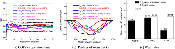
Figure 3. COFs versus operation time, profiles of worn tracks and wear rates of Cr3C2–NiCr+10%Ni/MoS2 coating at different temperatures.
Download figure:
Standard image High-resolution imageThe wear volumes of Cr3C2–NiCr+10%Ni/MoS2 coating at 25, 400 and 700 °C were 233, 284, and 363 mm3, respectively, which increased with the increase of operation temperatures, as shown in figure 3(b).
Figure 3(c) shows the wear rates of Cr3C2–NiCr+10%Ni/MoS2 and Cr3C2–NiCr coatings at the different temperatures. The wear rates of Cr3C2–NiCr coating at 25, 400 and 700 °C were 40.31 × 10⁻⁶, 31.57 × 10⁻⁶, and 31.93 × 10⁻⁶ mm3 · N–1 · s–1, respectively; while those of Cr3C2–NiCr+10% Ni/MoS2 coating at 25, 400 and 700 °C were 25.97 × 10⁻⁶, 30.06 × 10⁻⁶, and 11.86 × 10⁻⁶ mm3 · N–1 · s–1, respectively, which decreased by 35.6, 4.8, and 31.93% at the corresponding operation temperatures, respectively, showing that the Ni–coated MoS2 had excellent wear reduction performance at high temperature. This was because the Cr3C2 and MoC effectively reduced the adhesion tendency between the coating and the tribo–pair, in addition, the stress was partly reduced by the high elastic modulus and of large contact area of NiCr solid solution under the applied force, which effectively prevented the strengthening phase of Cr3C2 from peeling [35]. More importantly, the coating with the MoS2 self–lubrication phase formed the lubrication transfer film between the friction couples, the high stress was transformed into the indirect contact between the couple and the lubrication film, which effectively protected the coating to reduce the COFs. Therefore, the coating had self–lubrication at high temperature due to the functions of Cr3C2, MoC, NiCr and MoS2 phases.
3.4. Morphologies and XRD analyses of worn tracks
Figure 4(a) shows the morphology of worn track at 25 °C. The distinct scratches were formed on the sliding direction, the deep furrows and some pits appeared on the worn track, the wear mechanism was abrasive wear. The Cr3C2 was easily fell off under the action of shearing force to provide abrasive debris, forming a 'three–body' abrasive wear [36]. The lubrication film with the loose structure was easily peeled off due to the root fracture of columnar MoS2 platelets [37], which possessed good lubricious properties at low temperatures, while it did not result in the low COFs at high temperatures [38, 39]. At the same time, the fatigue wear occurred on the worn track under the repeated force, which easily produced occurred fatigue pits, as shown in figure 4(b). The EDS result on the marked part of A is shown in figure 4(c). The O with the mass fraction of 1.20% originated form the adsorbed impurities on the worn track, indicating that the oxidation wear did not occur in this case.

Figure 4. Morphologies and EDS analysis of worn track on Cr3C2–NiCr+10%Ni/MoS2 composite coating at 25 oC.
Download figure:
Standard image High-resolution imageFigure 5(a) shows the morphology of worn track at 400 °C. The spelled pits and furrows were obviously found on the smooth worn track, the MoS2 had the effect of friction reduction and lubrication, the wear mechanism was abrasive. The oxidation products appeared on the worn track, which was the result of friction reaction, as shown in figure 5(b). The EDS analysis result on the marked part of B is shown in figure 5(c). The O accounted for 18.56% of total mass fractions, indicating that the oxidation wear occurred on the worn track.

Figure 5. Morphologies and EDS analysis of worn track on Cr3C2–NiCr+10%Ni/MoS2 composite coating at 400 oC.
Download figure:
Standard image High-resolution imageFigure 6(a) shows the morphology of worn track at 700 °C. The scratches were shallow on the smooth worn track, there was no large peeling, which reduced the softening degree and effectively prevented the exfoliation of carbide particles. The oxidation products were also formed on the worn track, the wear mechanism was oxidation wear, as shown in figure 6(b). The EDS analysis result on the marked part of C is shown in figure 6(c). The O accounted for 33.72% of total mass fractions, indicating that the severe oxidation wear occurred on the worn track.
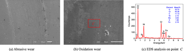
Figure 6. Morphologies and EDS analysis of worn track on Cr3C2–NiCr+10%Ni/MoS2 composite coating at 700 oC.
Download figure:
Standard image High-resolution imageThe abrasive wear occurred on the worn track at 25 °C, there were no oxidation phases, as shown in figure 7(a). The MoS2 formed the continuous and uniform film between the coating and the tribo–pair, and the small amount of MoS2 was oxidized to form the new MoS3 phase, as shown in figure 7(b). The MoS2 was oxidized at 350 °C [40], as a result, the wear mechanism was primary abrasive wear, accompanied by oxidation wear. The peaks of Cr2O3 and MoO3 in figure 7(c) indicated that the coating was oxidized, the formation of oxide film was conducive to reducing the COFs and preventing adhesion wear. From the above analyses, it can be seen that the continuous film did not form at 25 °C, the lubrication effect of MoS2 was not obviously found. The black sulphide lubrication film was formed on the worn track at 400 and 700 °C, the MoS2 was oxidized to form the MoO3 at 400 °C, and the Cr2C3 was oxidized to form the Cr2O3 at 700 °C [41], the formation of oxide layer played a synergistic role in the lubrication process.
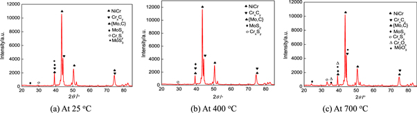
Figure 7. XRD analysis of worn tracks on Cr3C2–NiCr+10%Ni/MoS2 composite coating at different temperatures.
Download figure:
Standard image High-resolution image3.5. Wear mechanism
The mechanism of solid self–lubrication film in the initial friction period is shown in figure 8(a). The MoS2 lubricant was uniformly distributed on the coating, the motion state of tribo–pair was unstable due to its rough surface, and the extrusion deformation occurred on the contact zones and produced the friction heat, which accelerated the precipitation of MoS2 on the coating surface.

Figure 8. Lubrication model of MoS2 solid film on Cr3C2–NiCr+10%Ni/MoS2 composite coating.
Download figure:
Standard image High-resolution image
The subsequent extruded MoS2 particles were gradually enriched to accumulate on the coating, which were rolled to form a solid lubrication film [42, 43], as shown in figure 8(b).
The solid lubrication film was not completely coated on the worn track, the lubrication effect was not obviously found due to the insufficient number of MoS2 particles. The incomplete lubrication film was gradually supplied with the continuation of friction–wear process, the spherical MoS2 particles had the lubrication effect of ball bearings [44], the friction process was changed into rolling from sliding, which entered the normal period, as shown in figure 8(c).
In the subsequent friction–wear process, the solid lubricant was continuously supplied by the consumption of MoS2, which repaired the torn and peeled lubricant film and achieved the dynamic equilibrium state [45] The cracking probability increased with the further extension of tribo–pair, the speed of crack propagation accelerated, which was faster than that of repairing. At this time, the lubrication film kept falling off from the worn track, and leaving the spelled pits. The coating failure was accelerated, the serious damage of lubricating film is shown in figure 8(d).
4. Conclusions
- (1)The Cr3C2–NiCr+10% Ni/MoS2 coating is mainly composed of Ni–Cr and CrxCy hard phases, accompanied with the self–lubrication phases of MoS2, MoC and CrxSy, which reduce the COFs.
- (2)The average COFs of Cr3C2–NiCr+10%Ni/MoS2 coating at 25, 400 and 700 °C are 0.68, 0.55, and 0.35, respectively, which decrease with the increase of operation temperature, the formation of MoS2 solid film is the main factor of COF reduction.
- (3)The wear mechanism of Cr3C2–NiCr+10% Ni/MoS2 coating is abrasive wear at 25 oC, while those of at 400 and 700 °C are abrasive wear, accompanied by oxidative wear.