
Abstract
It is commonly accepted that single ausforming with small strain at low temperature promotes isothermal bainite transformation and leads to more retained austenite. In the present study, the effects of two-step ausforming on the bainite transformation and retained austenite in a Fe-C-Mn-Si medium-carbon bainitic steel were investigated by thermo-mechanical simulator, x-ray diffraction, scanning electron microscope and transmission electron microscope. The results show that the two-step ausforming cannot further promote the bainite transformation compared with single ausforming. However, the two-step ausforming enhances the mechanical stability of residual austenite due to more dislocations induced by the second deformation and therefore leads to more retained austenite. In addition, when the total strain is constant, the fraction of retained austenite increases with the increasing second strain. Moreover, the thickness of bainite plates treated with two-step ausforming is larger compared with single-step ausforming when the total strain is the same.
Export citation and abstract BibTeX RIS

Original content from this work may be used under the terms of the Creative Commons Attribution 3.0 licence. Any further distribution of this work must maintain attribution to the author(s) and the title of the work, journal citation and DOI.
1. Introduction
High-strength bainitic steels, mainly consisting of ultra-fine bainite ferrite and retained austenite, have excellent compressive mechanical property with ultra-high strength and good toughness [1–3]. The ultra-high strength is attributed to the fine bainite plates and good toughness is ascribed to the retained austenite [4–6]. The proportion of the bainite and retained austenite in the bainitic steels can be reasonably controlled by designing the processing parameters to obtain different mechanical properties. Therefore, many studies have been conducted on the effects of ausforming on bainite transformation, microstructure and retained austenite.
Prior strain introduces a large amount of dislocations in austenite and enhances the mechanical stability of austenite, thus influencing the subsequent bainite transformation [7]. So far, it is commonly known that single ausforming with large strain at low temperature retards the bainite transformation due to the mechanical stability of austenite, but small strain promotes the bainite transformation at a lower temperature [7–14]. For example, Zhao et al [8] studied the effect of ausforming in a medium C–Si rich alloy steel and claimed that large strains between 400 °C and 600°C promote bainite transformation. Hu et al [10] reported that deformation of 25% at 300 °C accelerates transformation, while 50% deformation hinders the bainite transformation in a superbainitic carbide-free steel. According to Zhang et al [13], ausforming reduces the incubation of isothermal bainite transformation and refines bainite lath in a medium-carbon Si–Al-rich alloy steel. Moreover, He et al [14] investigated the effect of multi-step warm rolling on the bainite transformation during the continuous cooling and declared that bainite transformation is promoted when the total strain is less than 30% compared with non-deformed steel. Summarizing the existing literature, it is found that most investigations focus on the effect of single-step ausforming on bainite transformation, microstructure and retained austenite during isothermal transformation, as well as the multi-step ausforming effect during continuous cooling process. Few study reported the effect of two-step ausforming on bainite transformation during isothermal transformation.
For single ausforming process, the deformed microstructure is full atstenite. However, for two-step ausforming process, the deformed microstructure consists of bainite and untranformed austenite after the first isothermal transformation because some bainite forms during the isothermal bainite transformation. Provided that the total strain is the same, compared with single ausforming, the two-step ausforming would introduce more dislocations. Thus, more austenite should be retained by two-step ausforming, thus affecting bainite transformation and final amount of retained austenite. Therefore, in the present study, the effect of two-step ausforming on bainite transformation and retained austenite was investigated. The results provide the reference for the design of processing technology of bainitic steels with better mechanical properties.
2. Experimental procedures
A medium-carbon high-strength bainitic steel with a chemical composition of Fe-0.43C-1.90Si-2.83Mn-0.57Al-0.06Cu (wt%) was studied in the present study. The steel was refined and then cast in the form of 50 kg ingot using a laboratory-scale vacuum furnace, followed by hot-rolling on a four-high mill to the plates of 12 mm in thickness and air-cooling to room temperature. At last, the experimental steel was tempered at 700 °C for 24 h in order to facilitate machining. The specimens for the thermo-mechanical simulation tests were machined in the form of a cylinder with 5.0 mm diameter and 10.0 mm height. The thermomechanical simulation experiments were conduct on a Gleeble 3500 simulator. The experimental procedures are presented in figure 1. The specimens were heated to 1000 °C at 5 °C s−1 and austenitized for 10 min, followed by cooling to 350 °C at 10 °C s−1. The cooling rate of 10 °C s−1 was large enough to avoid high-temperature transformation. The specimen A without deformation was isothermally held at 350 °C for 90 min for full bainite transformation followed by cooling to room temperature at 10 °C s−1. The specimen B was treated by single compressive deformation with 0.3 strain after cooling to 350 °C followed by isothermal holding for 60 min and then cooling to room temperature at 10 °C s−1. The specimens C and D were treated by two-step ausforming. They were compressively deformed to 0.2 and 0.1 strain in the first step, respectively, and then were isothermally held for 30 min for bainite transformation followed by compressive deformation with 0.1 and 0.2 strain in the second step. After the second deformation (the total strain in two steps is 0.3), the specimens C and D were isothermally held for 30 min again for bainite transformation. At last, two specimens were cooled to the room temperature at 10 °C s−1. For all deformed specimens, the strain rate is 1.0 s−1. According to the author's previous research [15, 16], there is no bainite transformation during deformation process for the medium carbon steels due to very short deformation time. For all cases, the thermal simulation data such as dilation, temperature and stress were automatically recorded by simulator. After thermal simulation experiments, the cylindrical specimens were deformed to be in the shape of drum. The specimens were wire cut and polished, followed by being etched with 4% nital. The microstructures at the middle of vertical section of specimens were observed on a Nova 400 Nano scanning electron microscope (SEM) operating at a voltage of 15 kV. Besides, a transmission electron microscope (TEM) was also used to observe the detail of microstructure. The volume fractions of retained austenite were determined by XRD tests on an x-ray diffractometer (X'Pert, XRD) with Co Kα radiation.

Figure 1. The experimental procedures.
Download figure:
Standard image High-resolution image3. Results
3.1. Dilatation curves
Figure 2 presents the diameter change of all specimens during the whole simulation experiment. The dilatations of all specimens were measured using a dilatometer fixed at the middle of the cylindrical specimen. The changes of middle diameter of specimens were recorded as dilatation. The dilatation caused by bainite transformation was recorded during the isothermal holding at 350 °C after deformation, excluding the dilatation change caused by deformation and temperature fluctuation. Figure 2(a) shows the diameter change with time of specimen A. Specimen A was heated from room temperature to 1000 °C and held for 10 min followed by cooling to 350 °C, contributing to the diameter change from zero point to point A. After that, specimen A was isothermally held at 350 °C for 90 min for full bainite transformation, leading to the gradual increase from point A to point B in the diameter. Therefore, the increase amount from point A to point B represents the amount of bainite transformation during the isothermal holding process. After point B, specimen A was cooled to room temperature, leading to the continuous decrease in diameter.

Figure 2. The dilatation curves of different treatment routes during the whole process: (a) specimen A; (b) specimen B treated by single ausforming; (c)–(d) specimens C and D treated by two-step ausforming.
Download figure:
Standard image High-resolution imageFigure 2(b) shows the dilatation curve of specimen B. The change of dilatation before point A was caused by heating, isothermal holding and cooling to 350 °C. Specimen B was compressively deformed to 0.3 strain when it was cooled to 350 °C, causing the vertical increase in dilatation (from point A to point B). From point B to C, the dilatation decreased due to elastic recovery. After point C, the deformed specimen B was isothermally held at 350 °C for 60 min for bainite transformation. According to author's previous study [15, 16], no bainite formed during the deformation at 1.0 s−1 due to a very short deformation time. Hence, the increase in dilatation from point C to point D represents the amount of bainite transformation in specimen B during the isothermal holding process at 350 °C.
Figures 2(c) and (d) show the dilatation-time curves of specimens treated by two-step deformation. Similar to the specimen B, the increasing dilatation after the first deformation represents the bainite transformation amount during 30 min holding at 350 °C. After that, the second deformation caused the vertical increase in dilatation. The decreasing dilatation (from point A to point B) was caused by the elastic recovery. Then, the specimen treated by two-step deformation was held at 350 °C for 30 min again. According to the dilatation curve after point B, there is no bainite transformation during the second holding process at 350 °C. Therefore, the increase amount during the first isothermal holding process after the first deformation represents the bainite transformation amount in specimen C. The diameter change of specimen D (figure 2(d)) represents the bainite transformation amount in specimen D.
Figure 3 shows the stress and temperature fluctuations of specimens A and B during the isothermal holding process. Figure 3 indicates that the temperature was constant during bainitc transformation, meaning that the change of dilatation was not affected by temperature. Moreover, according to the existing results [17–19], the stress during the isothermal holding obviously influences the bainite transformation. In order to eliminate the influence caused by stress, the stress during isothermal holding process after deformation for specimens B, C and D was controlled to a very small and similar value (6 ∼ 7 MPa). This small stress is necessary to hold specimens. Therefore, the dilatations of three deformed specimens are comparable because the influence of small stress was almost the same for deformed specimens. Besides, such small stress has little influence on the bainite transformation [9], meaning that the influence of stress can be ignored. It can be concluded that the dilation amount during the isothermal holding process represents the amount of bainite transformation.
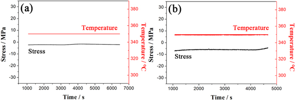
Figure 3. The stress and temperature fluctuations during the isothermal holding process, illustrating a very small stress and a well-controlled temperature in (a) specimen A and (b) specimen B.
Download figure:
Standard image High-resolution image3.2. The amount of bainite transformation
The diameters of deformed specimens were larger than non-deformed specimen. The diameter of specimen at the beginning of each isothermal holding process affects the subsequent dilation amount. Therefore, to compare the amount of bainite transformation in four specimens, the dilatation of specimens should be normalized using the formula  where
where  is the instantaneous dilatation during isothermal holding,
  is the initial dilatation (point A in figure 2(a), point C in figure 2(b)), and
  is the diameter corresponding to the starting point of isothermal holding at 350 °C [15, 20]. The normalized dilatation represents the relative diameter change of specimen caused by bainite transformation.
Figure 4 shows the changes of normalized dilatation of four specimens during isothermal bainite transformation. The bainite transformation rate of the specimen without deformation (specimen A) is very small. Apparently, the bainite transformation rates in deformed specimens are much larger than non-deformed specimens because of the promotion of bainite transformation by ausforming. Therefore, the total amounts of bainite transformation of deformed specimens are obviously larger than non-deformed specimen. Comparing the deformed specimens, it is found that the amount of bainite transformation slightly increases with the first increasing strain (0.3 strain for specimen B, 0.2 strain for specimen C and 0.1 strain for specimen D). These results obtained here indicate a good agreement with previous studies [7–13].
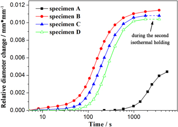
Figure 4. Relative diameter changes of four specimens caused by bainite transformation in logarithmic scale.
Download figure:
Standard image High-resolution imageFigure 5 shows dilatations for specimens C and D during the isothermal holding after the second deformation. It is noted that the dilatation is horizontal line during the second isothermal holding at 350 °C, meaning that there was no bainite transformation in specimens C and D after the second deformation. The amount of bainite transformation during the first isothermal holding represents the total bainite amount in specimens C and D. In other word, the second deformation cannot further promote the amount bainite transformation.

Figure 5. The dilatation changing with time during the second isothermal holding illustrating that no bainite transformation happens: (a) specimen C; (b) specimen D.
Download figure:
Standard image High-resolution image3.3. XRD
XRD was conducted to determine the fractions of retained austenite and the results are presented in figure 6. The integrated intensities of (200) γ, (220) γ, (311) γ, (200) α and (211) α diffraction peaks were determined. The volume fractions of RA can be calculated using the following formula (1) [21]:

where Vi is the volume fraction of austenite corresponding to each peak, and Iα and Iγ are the integrated intensities of the ferrite and austenite peaks, respectively. The following G values for each peak were used: 2.5 for Iα(200)/Iγ(200), 1.38 for Iα(200)/Iγ(220), 2.02 for Iα(200)/Iγ(311), 1.19 for Iα(211)/Iγ(200), 0.06 for Iα(211)/Iγ(220), and 0.96 for Iα(211)/Iγ(311) [21]. The calculation results are presented in figure 7.

Figure 6. Diffraction patterns for four specimens: (a) specimen A; (b) specimen B; (c) specimen C; and (d) specimen D.
Download figure:
Standard image High-resolution image
Figure 7. The fractions of retained austenite of different specimens.
Download figure:
Standard image High-resolution imageCompared with the non-deformed specimen, the fractions of retained austenite of deformed specimens are obviously larger. The 0.3 strain was applied on specimen B during the first deformation, that is, the first strain was 0.3, while the second strain was zero (0.3 + 0 strain). In addition, the strain applied on specimens C and D was 0.2 + 0.1 strain and 0.1 + 0.2 strain, respectively. Comparing the deformed specimens, it is found that the fractions of RA increase with the increasing second strain from 0 to 0.2. The amount of bainite transformation slightly decreases with the increasing second strain from 0 to 0.2, leading to a decrease in chemical stability. Therefore, it can be concluded that the fractions of RA mainly depend on the mechanical stability instead of chemical stability.
3.4. Microstructure
The microstructure was observed using SEM and presented in figure 8. The microstructure consists of bainite ferrite (marked by BF), film-like RA and M/A microstructure (marked by M/A). It is observed that the size of blocky M/A in non-deformed specimen is the largest (figure 8(a)), while the M/A of two-step deformed specimens is slightly smaller (figures 8(c) and 8(d)). And the size of M/A is very small in single-deformed specimen (figure 8(b)). For two-step deformed specimens, the amount of M/A microstructure increases with the second strain. Bainite transformation is accompanied with the rejection of carbon atoms into adjacent austenite, leading to the formation of film-like austenite locating between the BF [22, 23]. And the amount of film-like austenite depends on the amount of BF. Furthermore, comparing the micrographs of deformed and non-deformed specimens, it is found that the BF of deformed specimens is apparently shorter. In addition, the BF amount of non-deformed specimen (figure 8(a)) is smaller than deformed specimens. To quantitatively compare the fractions of BF in different specimens, a statistical method described in [24] was used. Figure 9 presents an example (specimen D) to illustrate the method. Five micrographs were selected to determine the fraction of BF for each specimen to reduce the error of the statistical results. The bainite volume fraction for specimen D is calculated to be 41.63%. For specimen A, B and C are 22.20%, 45.11% and 42.98%, respectively. The results obtained by quantitative microscopy analysis are consistent with the dilatometry results.
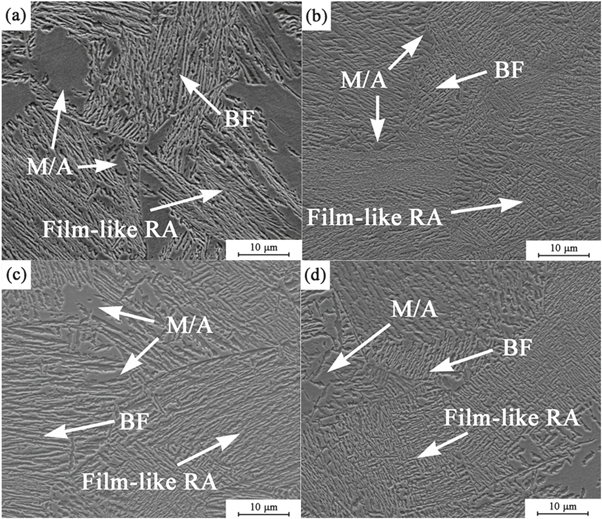
Figure 8. Microstructure of specimens: (a) specimen A without deformation; (b) specimen B with 0.3 strain; (c) specimen C with 0.2 + 0.1 strain; (d) specimen D with 0.1 + 0.2 strain.
Download figure:
Standard image High-resolution image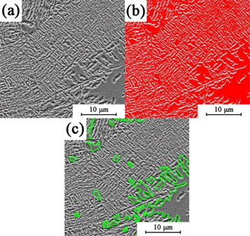
Figure 9. Example (for specimen D) illustrating the method of determining the volume fraction of BF: (a) the original micrograph; (b) the darker areas of bainite and M/A are colored red; (c) the blocky darker areas of M/A is marked with green line.
Download figure:
Standard image High-resolution imageFigure 10 gives the TEM bright field micrographs to show details of bainite laths (bright area) for the specimens with single-step ausforming and 0.1 + 0.2 strain. To quantitatively compare the thickness of bainite lath of two specimens, the thickness of bainite lath in five micrographs were measured. The average thickness of bainite laths of specimen with single-step strain was measured to be 0.27 ± 0.06 μm, while the thickness for specimen with two-step strain was 0.38 ± 0.09 μm. The thickness of bainite lath of the former specimen is smaller than the later specimen. In addition, the density of dislocations in figure 10(b) is obviously larger than figure 10(a). Even though the total strain of two specimens is the same, different treatment leads to different microstructure and dislocation density. For specimen treated by two-step deformation (0.1 + 0.2), the BF manly formed after the 0.1 strain. It is reported that bainite plates are finer with large strain [20]. Compared with specimen treated by single-step deformation (0.3 strain), the thickness of BF of the specimen with two-step deformation was larger because the first step strain was smaller than single-step ausforming.

Figure 10. Bainite laths in TEM: (a) specimen treated by single-step ausforming; (b) specimen treated by 0.1 + 0.2 strain.
Download figure:
Standard image High-resolution image4. Discussion
4.1. Bainite transformation
Comparing the amount of bainite transformation of specimen B and amount of the first bainite transformation of specimens C and D, it is observed that the extent to which bainite is promoted by prior strain slightly increases with strain (as shown in figure 4). This can be explained by the dual effects of ausforming. It is widely accepted that ausforming has dual effects on bainite transformation, that is, promotion of nucleation and retardation of growth. There is a competition between the two factors [25–27]. In the present study, the extent to which nucleation is promoted increases with the increasing strain from 0.1 to 0.3. Meanwhile, the retarding effect is much smaller compared with promotion effect when the strain is small. Therefore, the amount of bainite transformation slightly increases with strain.
Figure 5 indicates that there is no bainite transformation during the isothermal holding after the second deformation of 0.1 and 0.2, demonstrating that the second deformation cannot further induce chemically stabilized austenite transform into bainite. This can be explained as follows. The bainite transformation leads to an increase of carbon content in residual austenite. Moreover, the microstructure in TEM (figure 10(b)) shows that the carbon-rich residual austenite and bainite contain more dislocations after the second deformation compared with the specimen with single-step ausforming. According to Bhadeshia [25], bainite transformation occurs by the motion of phase interfaces which can be retarded by the dislocation debris introduced by deformation. These two factors contribute to a high chemical stability and mechanical stability in residual austenite. Hence, no bainite forms during the isothermal holding after the second deformation.
4.2. Retained austenite
The fraction of retained austenite depends on the amount of bainitic and martensitic transformation. The residual austenite after bainite transformation may transform to martensite during the subsequent cooling. Bainite transformation affects the morphology and carbon content of untransformed austenite, leading to the change of the kinetics of martensitic transformation [28, 29].
It is commonly recognized that the stability of residual austenite depends on chemical and mechanical stability as well as the morphology [29]. For non-deformed specimen, the bainite transformation during the isothermal holding leads to the carbon-rich austenite and a high chemical stability of residual austenite. Furthermore, the film-like austenite locating between bainite ferrite lathes, owing high stability, tends to be retained during the cooling process. For the specimen with single deformation, more bainite transformation leads to a higher chemical stability of residual austenite. Moreover, the applied strain introduces a large amount of dislocations, enhancing the mechanical stability of austenite. In addition, austenite grains are refined by deformation, resulting in the increase of austenite stability and suppressing the martensite transformation during the subsequent cooling process [30, 31]. Therefore, the fraction of retained austenite of specimen B is larger than specimen A.
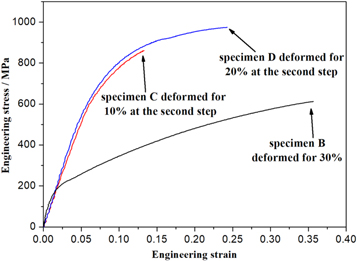
Compared with the specimen with single deformation, the fractions of retained austenite of two-step deformed specimens increase with the increase of the second strain from 0 to 0.2. The microstructure of specimens C and D consists of bainite and residual austenite before the second strain is applied. The residual austenite after the first step ausforming isothermal holding process in specimens C and D cannot totally exist at room temperature. Even though the untransformed austenite is stabilized after the first-step process, some austenite transforms into martensite during the cooling process from isothermal temperature to room temperature and other austenite will retain at room temperature. The amounts of bainite transformation for specimens B, C and D decreases successively, leading to successive reduction in the chemical stability of residual austenite in three deformed specimens. However, the fraction of RA of specimens B, C and D increases successively, indicating that the amount of RA mainly depends on the mechanical stability of residual austenite. More dislocations appear in the microstructure in figure 10(b), inferring that the density of dislocations in specimens B, C and D increases successively with the increase of the second strain from 0 to 0.2. Figure 11 presents the engineering stress-strain curves during compressive deformation of specimens B (the whole deformation process), C and D (the second step deformation process). The higher deformation resistance of specimens C and D demonstrates that more dislocations and work-hardening appear during the second step deformation. According to author's previous study [32], the austenite tends to be deformed prior to bainite, indicating that the largest degree of deformation is applied on austenite for specimen D. Hence, the mechanical stability of residual austenite for specimens B, C and D increases successively after the second strain. During the later isothermal holding process, static recovery may happen, reducing the density of dislocations. However, for medium-carbon steel (experimental steel), more carbon atoms in carbon-rich austenite are dissolved in austenite, results in a severe lattice distortion. The carbon atoms and lattice distortion hinder the motion of dislocations, thus reducing the static recovery. As a result, large amount of dislocations are remained. In such a case, mechanical stability dominates the stability of residual austenite. Consequently, the fractions of retained austenite of specimens treated by two-step ausforming are larger than single ausforming. In addition, the RA fraction of specimen D is larger than specimen C due to a larger second strain for specimen D.
Figure 11. Engineering stress-strain curves during the whole deformation for specimen B and the second step deformation for specimens C and D.
Download figure:
Standard image High-resolution image
5. Conclusions
The effects of two-step ausforming on the bainite transformation and retained austenite in a Fe–C–Mn–Si high-strength bainitic steel were investigated. Based on the experimental results, the following conclusions can be obtained:
- (1)The two-step ausforming does not further promote the bainite transformation compared with single ausforming when the total strain is the same.
- (2)The two-step ausforming further enhances the mechanical stability of residual austenite and leading to more retained austenite. Besides, when the total strain is constant, the fraction of retained austenite increases with the second strain.
- (3)The thickness of bainite plates treated with two-step ausforming is larger compared with single-step ausforming when the total strain is the same.
Acknowledgments
The authors gratefully acknowledge the financial supports from the National Natural Science Foundation of China (Nos. 51874216 and 51704217), the Major Projects of Technology Innovation of Hubei Province (No. 2017AAA116), the Science and Technology Project of Wuhan (2018010402011187) and Hebei Joint Research Fund for Iron and Steel (E2018318013).