
Abstract
The application prospects of dielectric materials such as poly(vinylidene fluoride) (PVDF) based polymers in the field of energy storage have stimulated extensive research. In this study, the energy storage characteristics of poly(vinylidene fluoride-hexafluoropropylene) (P(VDF-HFP)) films crystallized from several solvents with different vapor pressure were investigated. The charge-discharge efficiency of the P (VDF-HFP) film crystallized from N, N-dimethylformamide (DMF) demonstrates an efficiency of 85% under an electric field of 1000 kV cm−1, which is 1.42 times of the film crystallized from dimethyl sulfoxide (DMSO). Meanwhile, the insulation resistivity of the film crystallized from DMF is also higher than other films, and the energy storage characteristics are optimal in this study. This work provides guidance for the preparation of PVDF-based polymer films using the solution method.
Export citation and abstract BibTeX RIS

Original content from this work may be used under the terms of the Creative Commons Attribution 4.0 licence. Any further distribution of this work must maintain attribution to the author(s) and the title of the work, journal citation and DOI.
1. Introduction
Electrostatic film capacitors have important applications in military and civilian applications, including electric vehicles, high voltage direct current transmission, medical devices, and many other fields. However, the existing film capacitors still have low energy storage performance, which limits their application. Therefore, it is important to improve the energy storage performance of the capacitor dielectric material. In the past few decades, poly(vinylidene fluoride) (PVDF) based polymers have become a hot research topic for their excellent electrical, thermal, chemical and mechanical properties [1–3]. PVDF is a kind of homopolymer which is polymerized from vinylidene fluoride (VDF) monomer [4]. It exhibits high dielectric constant (8 ∼ 12), high breakdown field strength (∼5000 kV cm−1) and lower dielectric loss (∼1.8%), which is considered as a promising candidate material for film capacitors. However, PVDF also has some disadvantages, such as polarization saturation under low electric field and high loss under high electric field [5]. In order to improve its energy storage characteristics, copolymerizing with other low dipole moment monomers to form a copolymer is proved an effective way. For instance, chlorotrifluor ethylene (CTFE) and hexafluoropropylene (HFP) were polymerized with VDF monomer to form PVDF-based copolymers. The addition of the second monomer reduces the ferroelectric domain size of the polymer, which makes the material have relaxation ferroelectric behavior and can significantly improve the polarization properties of the polymer [6–9].
In this work, poly(vinylidene fluoride-hexafluoropropylene) (P(VDF-HFP)) was investigated as a dielectric material. The corporation of amorphous HFP group with VDF monomer results in the increase of fluorine content, making P(VDF-HFP) more hydrophobic than PVDF which can reduce the impact of air humidity [10, 11]. The addition of HFP monomer also reduces the glass transition temperature of the polymer, increasing the degree of amorphization, which can effectively improve the flexibility of the film [12–14]. There have been studies on the effects of molecular weight and solvent on the energy storage properties of PVDF film [15, 16]. The preparation of P(VDF-HFP) film by solution casting has been widely used, but the influence of different solvents on P(VDF-HFP) film is seldom be investigated. In order to obtain the influence of solvent on the energy storage property of P(VDF-HFP), solvents with different vapor pressure, including N, N-dimethylformamide (DMF), N, N-dimethylacetamide (DMAc), dimethyl sulfoxide (DMSO), and N-methylpyrrolidone (NMP) were selected, which are common organic solvents and are capable of dissolving various polymers including PVDF-based polymers. The effects of different solvents on the dielectric and energy storage properties of P(VDF-HFP) were investigated. The charge-discharge efficiency calculated from P-E hysteresis loops, leakage current and insulation resistivity of P(VDF-HFP) films were also investigated in detail. Studying the influence of solvent on the dielectric properties and energy storage properties of P(VDF-HFP) can provide experimental guidance for the application of PVDF-based polymers in the field of high energy storage film capacitors.
2. Experiments
2.1. Material
DMF, DMAc, DMSO, and NMP were purchased from Chengdu Kelong. P(VDF-HFP) was supplied by Sigma-Aldrich (Solef 427160, Mw ∼ 400,000, Mn ∼ 130,000). All chemicals were used as received.
2.2. Preparation of P(VDF-HFP) films
Firstly, P(VDF-HFP) was dissolved in DMF, DMAc, DMSO, NMP solvent with a concentration of 15 wt%, mechanically stirred at room temperature for 24 h until completely dissolved. Then, P(VDF-HFP) films were prepared by the solution casting method on glass substrates, and the thickness of the P(VDF-HFP) film was controlled by the height of the wet film scraper. Finally, the samples removed the solvent at 60 °C for 12 h to sure the solvent was completely evaporated, then cooled the films (about 8 μm) to room temperature and peeled off from the substrate for measurement.
2.3. Characterization and electrical properties measurement
The crystallization properties and phases of the P(VDF-HFP) films were characterized by Fourier-transform infrared spectroscopy (FTIR, 8400 S, Shimadzu), x-ray diffraction (XRD, Malvern Panalytical, Inc.), and differential scanning calorimeter (DSC). The surface microstructures of the films were observed by Scanning electron microscopy (SEM). The thickness of films were measured by a magnetic induction thickness-meter (Fischer DUALSCOPE MPO). Before conducting the electrical performance test, aluminum electrode was evaporated on both surfaces of the samples by using vacuum coating equipment (Chengdu Qihe vacuum coating equipment co. LTD, China). Dielectric spectrum characteristics were measured by using a precision impedance analyzer (4294 A, Agilent Technologies, Inc.) from 100 Hz to 1 MHz. P-E hysteresis loops and leakage current of films were measured by using a ferroelectric tester (Radiant Technologies, Inc.).
3. Results and discussions
3.1. Characterization of P(VDF-HFP) films
The basic information of four kinds of solvents with different vapor pressure is listed in table 1. DMF posses the highest solvent vapor pressure which means a relatively short drying time under the same condition. FTIR characterization of P(VDF-HFP) films crystallized in different solvents is shown in figure 1. As shown in FTIR spectrum, the absorption peaks at 483 cm−1 and 879 cm−1 are the amorphous phase absorption peak of P(VDF-HFP), while the absorption peaks at 511 cm−1, 602 cm−1, 812 cm−1, and 839 cm−1 are attributed to the β phase absorption peaks of P(VDF-HFP) films. In addition, the absorption peaks at 532 cm−1, 615 cm−1, 764 cm−1, 796 cm−1, 855 cm−1 and 976 cm−1 are α phase absorption peaks of the P(VDF-HFP) films [17, 18]. Characteristic absorption peaks of β phase were observed in all four samples. In addition to the films crystallized from DMSO, the other three films showed weak α phase absorption peaks. Figure 2 shows the XRD characterization of P(VDF-HFP) films. In figure 2, there is a wide x-ray diffraction peak at 2θ ≈ 20.32°, which is the diffraction peak of β phase on the (110) and (200) crystal planes [19]. The results of XRD are fit well with the results of FTIR, which demonstrates that the crystal structure of P(VDF-HFP) films crystallized in different solvents are mainly β phase. The results of DSC are shown in figure 3. As seen from the results, the percentage of crystallinity (XC) of the film crystallized from NMP (24.06%) is a little higher than that of other three films [20]. With the change of the solvent vapor pressure, the melting point of the films also increase slightly, these phenomena may be caused by the more complete crystalline state of the films.
Table 1. The basic information of the solvents used [15, 21, 22].
| Solvent | Molecular formula | Relative molecular mass | Vapour pressure |
|---|---|---|---|
| DMF | C3H7ON | 73.10 | 490 Pa(25 °C) |
| DMAc | C4H9ON | 87.12 | 170 Pa(25 °C) |
| DMSO | C2H6OS | 78.13 | 59 Pa(25 °C) |
| NMP | C5H9ON | 99.13 | 45 Pa(25 °C) |
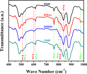
Figure 1. FTIR spectra of P(VDF-HFP) films crystallized from different solvents.
Download figure:
Standard image High-resolution image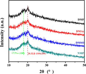
Figure 2. XRD image of P(VDF-HFP) films crystallized from different solvents.
Download figure:
Standard image High-resolution image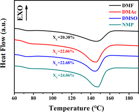
Figure 3. DSC test results of P(VDF-HFP) films crystallized from different solvents.
Download figure:
Standard image High-resolution image3.2. Dielectric performances of P(VDF-HFP) films
The dielectric spectrum of P(VDF-HFP) films are shown in figure 4, the relative dielectric constant  of the P(VDF-HFP) films crystallized from DMF and NMP are basically the same throughout the test frequency range, and the
  of the P(VDF-HFP) films crystallized from DMAc and DMSO are slightly lower than that of the other two samples. P(VDF-HFP) is a polar polymer with a long molecular chain extending from the crystalline region to the amorphous region. The β phase provides a large dipole moment which leads to a high dielectric constant. It is precisely because the four films are dominated by the crystal form of the β phase, hence, the dielectric constants differences of them are illegible. However, as the frequency increases, the contribution of the molecular dipole moment is gradually reduced, therefore the dielectric constant decreases as the frequency increases. The dielectric loss tan δ of the four samples almost completely coincided in the entire test band, and the tan δ at 1 kHz was only 0.04. In a word, the solvent has little effect on the dielectric spectrum characteristics of the P(VDF-HFP) film.
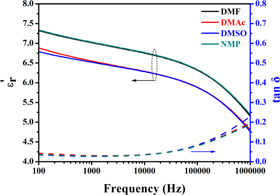
Figure 4. Dielectric spectrogram of P(VDF-HFP) films crystallized from different solvents.
Download figure:
Standard image High-resolution image3.3. Energy storage characteristics of P(VDF-HFP) films crystallized from different solvents
Figure 5 shows the unipolar P-E hysteresis loops of the P(VDF-HFP) films crystallized from different solvents. Compared with the P(VDF-HFP) films crystallized from DMF and DMAc, the P(VDF-HFP) films crystallized from DMSO and NMP have relatively large polarization and remanent polarization, and the P-E loops also occupy a larger area. During the solidification of the liquid film, the evaporation behavior of solvents would show a distinct influence on the performance of obtained dielectric films, and the evaporation behavior of the solvent is mainly determined by the vapor pressure [15, 23–26]. Moreover, the vapor pressure of these solvents changes gradually, for example, the vapor pressure of these solvents at 25 °C is DMF(∼490 Pa) > DMAc(∼170 Pa) > DMSO (∼59 Pa) > NMP(∼45 Pa) (as shown in table 1). It's obvious to see that the vapor pressure of DMF solvent is higher than the other three solvents at the same temperature [22, 27], which explains the reason why DMF evaporates rapidly during the solidification process. Other solvents have a much lower vapor pressure, which greatly prolongs the evaporation time of the solvent, resulting in a long crystallization time of the film. Hence, a more complete crystal structure can be formed in the low-vapor-pressure solvent, which means a larger ferroelectric domain can be formed [28]. The reverse transformation of large ferroelectric domain is much more difficult, resulting in large residual polarization and loss under alternating electric fields. The P-E hysteresis loops of the P(VDF-HFP) film crystallized from DMSO is the widest, attributed to the strong water absorption of DMSO. The sulfoxide group is highly hydrophilic, and the two lone pairs of electrons carried by the oxygen atoms in the group can generate two hydrogen bonds with water molecules in the air, so it is easy to absorb water. For instance, DMSO can absorb 70% of its own weight of water from the air under the air temperature is 20 °C and the relative humidity is 60%. Although the experimental environment for preparing the films is controlled at a temperature of 20 °C and relative humidity of 48%. However, the moist air can't be absolutely avoided. When the DMSO solution was prepared as a liquid film on a glass substrate, the surface of the liquid film became foggy and accompanied by solidification after exposure to the air for a period of time. The high-humidity environment causes the originally smooth and dense film to become a loosely connected particle of a block structure [29], which also causes many holes on the surface of the film (see figure 6(d)). The surface morphology of the films was scanned by SEM as shown in figure 6, there are many holes with different sizes appear on the surface of the film crystallized from DMSO and NMP. When the liquid film is in the heated state, the solvent molecules constantly escape, causing the gas phase pressure above the liquid film to increase, and the water molecules in the air will become liquid phase into the liquid film. A small amount of solvent molecules are escaping when the vapor pressure of solvents is low, and a large amount of water molecules enter the surface of the liquid film to form a pore structure. The phenomenon originates from vapor-induced phase separation (VIPS). These loose pore structures increase the leakage current of the film and generate more energy loss in application. In general, the P(VDF-HFP) film crystallized from high vapor pressure solvent has relatively smooth and dense surface morphology, which is conducive to energy storage.
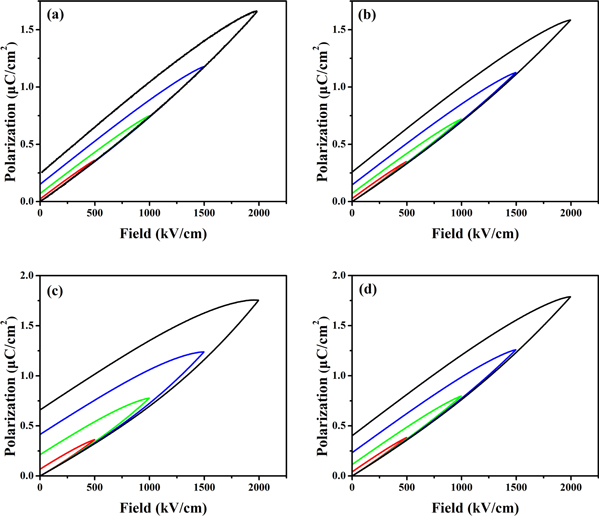
Figure 5. P-E hysteresis loops of P(VDF-HFP) films crystallized from different solvents. (a) DMF, (b) DMAc, (c) DMSO, (d) NMP.
Download figure:
Standard image High-resolution image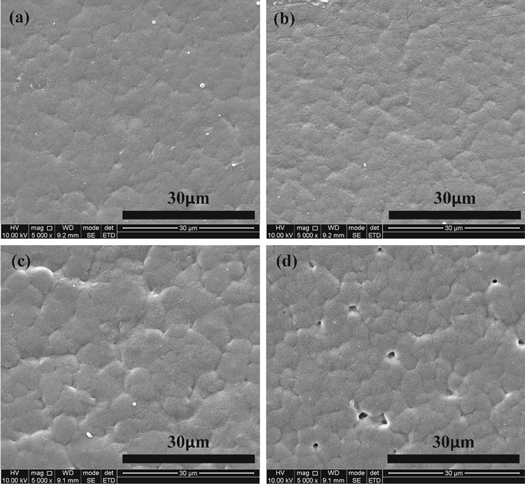
Figure 6. SEM images of the four films. (a) DMF, (b) DMAc, (c) NMP, (d) DMSO.
Download figure:
Standard image High-resolution imageThe charge-discharge efficiency and the energy storage density under several typical electric fields were calculated by P-E hysteresis loops, as shown in figure 7. Since P-E hysteresis loops of the P(VDF-HFP) film crystallized from DMSO is relatively wide, hence, the charge-discharge efficiency is much lower than that of the other three films. As mentioned above, the film crystallized from a solvent with low vapor pressure has a larger spherulite size and will form a larger ferroelectric domain in the crystalline region of the film. The switching of ferroelectric domains relies on the crystalline size. Therefore, large-sized ferroelectric domains cause an increase in residual polarization and ferroelectric loss in the reversal process, which results in reduced charge-discharge efficiency. When the electric field strength reaches 1000 kV cm−1, more than 80% of the charge-discharge efficiency of the P(VDF-HFP) films crystallized from DMF and DMAc are kept, and the charge-discharge efficiency of the P(VDF-HFP) film crystallized from NMP is maintained at 76%. In addition, it can be seen in figure 7(b) that the storage density of the film crystallized from DMSO is significantly lower than the other three films under the same electric field. Interestingly, the energy storage density of films crystallized from NMP is not as low as that of DMSO. Compared to the film crystallized from DMF, although the energy storage density is similar, the charge-discharge efficiency is much lower than the latter, which means more energy loss. The above results indicate that when DMF is used as a solvent, the prepared film has obvious advantages in energy storage characteristics. The leakage current of the P(VDF-HFP) films was measured by ferroelectric tester. The result is shown in figure 8, the leakage current of the P(VDF-HFP) film crystallized from DMSO (exceeds 2.5 μA at an electric field strength of 1000 kV cm−1) is significantly higher than that of the other three films. The results of the films crystallized from DMF and DMAc have no significantly different, the leakage current is almost less than 1 μA. It is worth noting that there is an intersection between 800 kV cm−1 and 1000 kV cm−1 leakage current curve in figure 8(d). This may be attributed to that in the test process individual areas appear self-healing points [30], which were the original conductive paths. Due to the disappearance of the conductive path and defect after self-healing process, the insulating performance of the film enhanced and cause the decrease of the leakage current, finally generates an intersect between 800 kV cm−1 and 1000 kV cm−1.
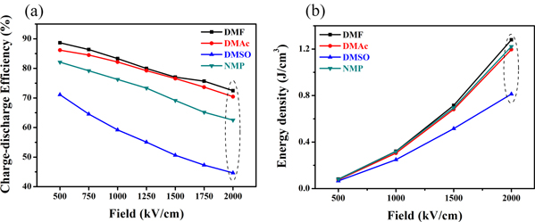
Figure 7. (a) Charge-discharge efficiency of P(VDF-HFP) films crystallized from different solvents and (b) energy storage density.
Download figure:
Standard image High-resolution image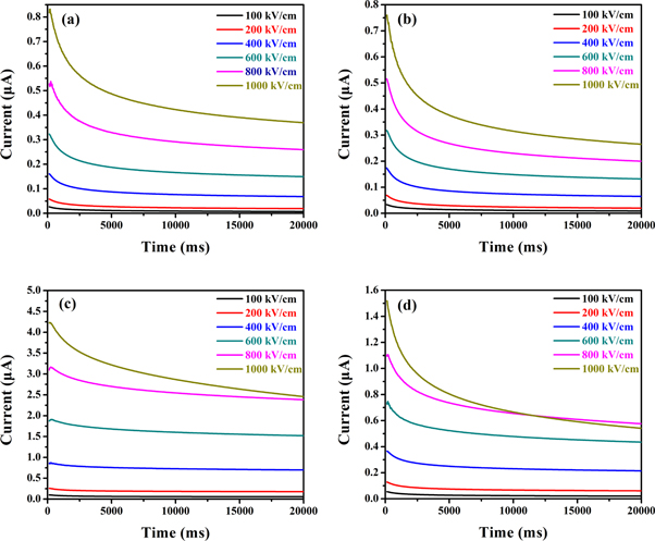
Figure 8. Leakage current of P(VDF-HFP) films crystallized from different solvents. (a) DMF, (b) DMAc, (c) DMSO, (d) NMP.
Download figure:
Standard image High-resolution imageThe dielectric material in the film capacitor is not a perfect insulator, and the leakage current is ubiquitous. The leakage current of the dielectric film can be expressed as:

Where U is an applied voltage and RI is an insulation resistance. RI can be calculated by another equation:

Which ρI is insulation resistivity, the d is the dielectric film thickness, and A is the area of the aluminum electrode evaporated on the dielectric film (the metalized area of the P(VDF-HFP) sample is 1.2 cm*1.2 cm). The following formula can be obtained from equations (1) and (2):

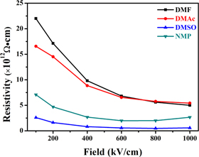
Where E is the applied electric field, the insulation resistivity of the P(VDF-HFP) films was calculated by formula (3) (as shown in figure 9). The insulation resistivity of samples crystallized from DMF and DMAc is not much different and decreases with the electric field increasing. In general, the insulation resistivity of the four samples was ranked as DMF > DMAc > NMP > DMSO, which is basically consistent with the size of the solvent vapor pressure. It is shown that the higher the solvent vapor pressure is, the higher the resistivity of the P(VDF-HFP) film has.
Figure 9. Insulation resistivity of P(VDF-HFP) films crystallized from different solvents.
Download figure:
Standard image High-resolution image
4. Conclusion
In this paper, P(VDF-HFP) films crystallized from four different solvents were introduced. The crystal form of P(VDF-HFP) films crystallized from DMF, DMAc, and NMP contained both α phase and β phase crystal forms, of which β phase was dominant. The solvent has little effect on the P(VDF-HFP) dielectric characteristics. However, the solvent shows a great influence on the charge-discharge efficiency and the insulation resistivity of the dielectric film. The charge-discharge efficiency and the insulation resistivity of the P(VDF-HFP) film crystallized from DMF are the highest, which is more suitable for high energy storage field applications.
Acknowledgments
This work was funded by the National Natural Science Foundation of China (Grant No. 61774030 & 61971112), the University Natural Science Research Project of Jiangsu Province (No. 19KJB470035), Chongqing Postdoctoral Science Special Foundation (No. Xm2017051), and Chongqing Engineering Research Center of New Energy Storage Devices and Applications (No. KF20170202, KF20180202).