
Abstract
In this study, magnesium alloy (AZ91D) matrix composites reinforced with 1 wt% of nano alumina (n-Al2O3) were fabricated using novel Ultrasonic Treatment (UST) assisted squeeze casting method. UST was carried out at four different levels of ultrasonic power namely, 0 W (without UST), 1500 W, 2000 W and 2500 W at constant frequency and time. The composites were heat-treated at T6 condition under argon gas protected environment. Microstructural analysis was done using optical microscopy and high-resolution scanning electron microscopy. Physical, mechanical and tribological properties of the composites were evaluated. A significant refinement in grain structure and improvement in porosity was seen on an increase in UST power. Improvement was seen in micro-hardness, yield strength, ultimate tensile strength and % of elongation of the composite fabricated at 2500 W by 18%, 48%, 28%, and 10% respectively compared to an untreated composite. The composite fabricated at 2500 W showed less wear rate and coefficient of friction when compared to other composites at all sliding conditions. Scanning electron microscope images of the worn surface of the composite pins revealed that the wear mechanisms dominated were abrasion, adhesion, oxidation and delamination.
Export citation and abstract BibTeX RIS

Original content from this work may be used under the terms of the Creative Commons Attribution 4.0 licence. Any further distribution of this work must maintain attribution to the author(s) and the title of the work, journal citation and DOI.
1. Introduction
Magnesium alloys are lightweight materials with attractive mechanical properties suitable for aerospace and automotive applications for increasing energy efficiency and reducing greenhouse gas emission [1]. AZ91D magnesium alloy is primarily used for die casting due to its better castability and superior mechanical properties at room temperature [2]. AZ91D consists of Al (9 wt%) and Zn (1 wt%) as the major alloying elements. Magnesium matrix composites possess high specific strength, low density, good damping capacity, good castability, good machinability and better corrosion and wear resistance when reinforced with hard ceramic materials such as Al2O3, SiC, B4C, TiC, TiB2 etc [3, 4]. Among these, Al2O3 (Alumina) is a thermally stable ceramic reinforcement with high hardness, high strength, high stiffness, excellent oxidation resistance, and low cost. Nano alumina (n-Al2O3) particulate reinforcement makes a remarkable improvement in the grain size, mechanical and tribological properties of the composites [5, 6].
Stir casting method is mostly employed for fabricating metal matrix composites. The major problems seen during the fabrication of nanocomposites through use of the stir casting method lie in the requirement of a long stirring time for attaining uniformity in distribution of the nano reinforcement particles. Also, long stirring time causes oxidation to the magnesium matrix often resulting in poor quality casting. Reduction in the stirring time is necessary to ensure the improvement of the quality of the casting [7]. Besides, the higher surface to volume ratio and poor wettability of nanoparticles cause agglomeration which leads to deteriorated grain structure. A novel Ultrasonic Treatment (UST) in the composite melt is taken up for overcoming these issues [8–10]. UST eliminates the nanoparticle clusters of agglomeration and efficiently disperses them throughout the metal matrix by 'cavitation effect'. Cavitation effect is a phenomenon which forms and implodes micro vapour bubbles due to a sudden change in pressure in the melt [11–13]. The multiplied implosion of the bubbles produces high temperature and pressure spots in the melt. These hot spots in the melt cause release of a large amount of energy which promotes the wettability of nanoparticles and disperses them throughout the matrix melt. Besides, UST promotes the degassing effect during the melting [14]. Blending of squeeze pressure during the solidification of composites alleviates the casting defects of shrinkage and porosity [15–17].
A refined and uniform grain structure is most important for obtaining good mechanical and tribological properties of composites [18–20]. Recently, many advanced material processing techniques are employed for modifying the microstructure of the magnesium-based composites [21–23]. Among, ultrasonic treatment processing receives great attention as it ensures more uniformity in the dispersion of nanoparticles in the metal matrix. Many researchers have focused on variations in the ultrasonication parameters such as ultrasonication time, power, and frequency for attaining a fine and uniform grain structure. Habibnejad-Korayem et al have reported enhancement in the properties of AZ31-alloy through reinforcement with different wt% (0, 0.5, 1, and 2) of n-Al2O3 particles using the stir casting method. The results showed an increase in the alumina content causing a reduction in the grain size and improvements in hardness and tensile strength of the Mg-alloy [24]. Sameer Kumar et al studied the effects of the addition of different wt% of n-Al2O3 particles in AZ91E alloy through use of the semi-solid stir casting method. The study revealed an increase in macro hardness and tensile strength of the composite up to 22.5% and 26.54% respectively compared to base alloy [25]. Xinbao Liu et al and Deming Gao et al examined the microstructure and mechanical properties of UST assisted AZ91 alloy. The results revealed refinement in grain structure due to faster heterogeneous nucleation during the solidification and significant enhancements in mechanical properties by an increase in UST power [26, 27]. He Bolin et al established the occurrence of a significant improvement in the microhardness and wear resistance of AZ91D alloy compared to an untreated AZ91D alloy through an increase in the current and UST power [28]. Nie et al fabricated AZ91/SiCp composite using the ultrasonication method with different stirring times (5 min, 10 min and 25 min). Their experiments showed a stirring time of 5 min empowering the mechanical properties. With an increase in the stirring time, there was a decrease in the tensile properties of the AZ91/SiCp composite [29]. Tzanakis et al investigated the influencing factors of the cavitation intensity of UST during the casting of aluminium. The results showed the optimum power setting acquiring the maximum cavitation intensity at 3.5 kW. A drop-in temperature causes an enlargement in pressure fields in the acoustic cavitation zone. This increases the efficiency of the melt treatment [30]. Srivastava et al observed the grain morphology of binary Al–Si, Al–Cu and Al–Ni alloys through variations in the ultra-sonication intensity. They saw a decrease in the grain size with increasing ultrasonic intensity [31]. UST assisted squeeze casting of a wrought Al alloy was investigated by Gang Chen et al who found improvement in tensile strength, yield strength and elongation by 20.8%, 21.2% and 84.8% respectively as a result of an increase in the UST power from 0 to 1.8 kW [32]. Chen Ruirun et al. have reported a modification in coarse dendrite grain into fine non-dendrite grain due to the application of ultrasonic vibration [33]. Guangyu Yuan et al. studied the influence of heat treatment on thermal characteristics of AZ91D alloy made in different casting methods. This study revealed dissolution of β-Mg17Al12 phases in Mg-matrix during theT4 heat-treatment and again formed through T6 heat-treatment [34]. Soundararajan et al fabricated the A356-20 wt% SiC composites through mechanical stirring and UST assisted squeeze casting. The results revealed that ultrasonically treated composites possessed better mechanical and physical properties over the mechanically stirred composites [35]. Details of previous works based on UST parameters such as ultrasonication power, frequency and time are provided in table 1.
Table 1. Summary of research articles based on UST parameters.
| Referred work | Material | UST Power (kW) | UST Time (Min.) | UST Temp. (°C) | References | Year |
|---|---|---|---|---|---|---|
| Prasad Reddy et al | AA6061-SiC-Gr | 2.4 | 25 | 750 | [8] | 2019 |
| Soundararajan et al | A356%-20% SiC | 2.5 | 5 | 700 | [35] | 2019 |
| Gang Chen et al | Al 2024 | 0, 0.6, 1.2, 1.8 | 0.5 | 700 | [32] | 2019 |
| Puga et al | Cu–Zn alloy | 4 | 4 | 900–940 | [19] | 2019 |
| Jiping Lei et al | A380-Sr–Sc | 1 | — | 640 | [18] | 2018 |
| Qiang Li et al | Al–SiC | — | 5 | 850 | [20] | 2018 |
| He Bolin et al | AZ91D | — | 0, 3, 6, 9 | — | [28] | 2017 |
| Qi Gao et al | Al-4.5Cu–TiB2 | 2.8 | 1,2,4 | 720 | [14] | 2017 |
| Apratim et al | AZ31- Nano Al2O3 | 1.5 | 3 | 650 | [10] | 2017 |
| Srivastava et al | Al–Ni, Al–Cu, Al–Si | 0, 0.35, 1.4 kW cm−2 | — | 700 | [31] | 2017 |
| Han-song et al | Mg−6Zn−0.5Y−2Sn | 0, 0.3, 0.5, 0.7 | 0.5 | 680 | [11] | 2016 |
| Tzanakis et al | Pure Al | 2, 2.5, 3, 3.5, 4 | 0.5 | 710–770 | [30] | 2016 |
| Chen Ruirun et al | Ti–44Al–6Nb–1.0Cr-2.0 V | 1.2 | 0, 0.42, 0.83, 1.67 | — | [33] | 2016 |
| Yue-shuang et al | AZ91 alloy | 0, 0.4, 0.6, 0.8, 1 | 1.67 | 680 | [12] | 2014 |
| X J Wang et al | AZ91-SiC | 0.6 | 10, 20, 30 | 700 | [7] | 2014 |
| Nie et al | AZ91-SiC | 2 | 20 | 720 | [29] | 2011 |
| Deming gao et al | AZ91 | 0, 0.3, 0.5, 0.7 | — | 730 | [27] | 2009 |
| Xinbao Liu et al | AZ91 | 1.2 | — | 720 | [26] | 2008 |
Literature shows the applications made by many researchers on UST in the composite melt for dispersing nano particulate reinforcements by controlling the frequency, power and time of UST. Nevertheless, very little work reported on the influence of UST power on the microstructure, mechanical and tribological characteristics of nanocomposites. Therefore, this study focuses on the development of AZ91D/n-Al2O3 composites through variations in the ultrasonication power intensity viz 1500, 2000 and 2500 Watts at constant ultrasonication frequency and time. The effects of ultrasonication power intensity on the physical, microstructural, mechanical and tribological properties have been analysed and comparisons have been made with the composite prepared without the assistance of UST (0 Watts).
2. Materials and methods
2.1. Specimen preparation
In the present investigation, AZ91D alloy with elemental composition as shown in table 2 was used as the matrix material. Nano alumina particles (n-Al2O3) having an average particle size of 20–30 nm (density-3.95 g cm−1−3 and purity-99.95%) was used as the reinforcement. Composites were fabricated using a UST assisted stir-squeeze casting set up supplied by SwamEquip, India. When the temperature of the furnace reached 800 °C, 1 kg of AZ91D magnesium alloy was added to the cylindrical furnace and thermocouple placed inside the furnace for monitoring the melt temperature. Considering magnesium inflammable at a high temperature, melting was carried out in a protected environment of an inert gas mixture of Argon (90%) and SF6 (10%). A mechanical stirrer was dipped into the melt and allowed to rotate at 400 rpm for the amalgamation of all the molten metals. Preheated n-Al2O3 powder was then mixed in the melt with the assistance of an inbuilt vibrator and stirred well with liquid metal. After adequate stirring, an ultrasonic probe was immersed in the melt to produce ultrasonic waves. An acoustic generator coupled with transducer (Max. power-2500 W and frequency-20 kHz) was used. Four power levels of UST were selected, viz 0 W (without UST), 1500 W, 2000 W and 2500 W for the fabrication of the composites. The UST was performed in the melt for a constant time of 15 min. Finally, the molten metal (750 °C) was bottom poured into a preheated (300 °C) split type squeeze die and a squeeze pressure of 120 MPa was applied for about 1 min. The schematic arrangement of magnesium stir casting with titanium ultrasonic probe and UST power controller module are shown in figures 1(a)–(c).
Table 2. Elements of the AZ91D alloy.
| Element | Al | Zn | Mn | Si | Fe | Cu | Ni | Mg |
|---|---|---|---|---|---|---|---|---|
| Wt% | 8.5 | 1 | 0.15 | 0.1 | 0.005 | 0.03 | 0.002 | Balance |
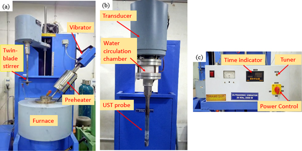
Figure 1. (a) Mg stir casting set up, (b) titanium ultrasonic probe, (c) UST power controller.
Download figure:
Standard image High-resolution image2.2. Heat treatment
The composites were heat-treated using a muffle furnace (Servo Enterprises, India) under argon gas protected environment at T6 condition. Solution treatment (T4) was performed at 415 °C for 16 h followed by water quenching considering heat treatment temperature is critical for obtaining the desired microstructure and mechanical properties of the composites. Ageing was done at 168 °C for 16 h. Figure 2 illustrates the heat treatment process followed in this study.
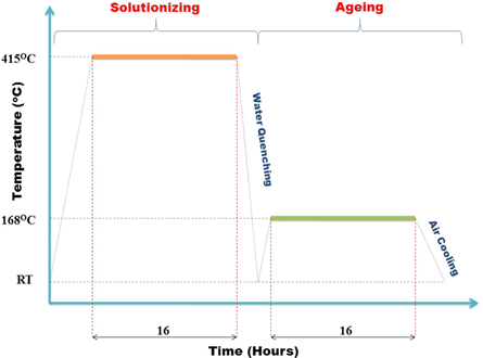
Figure 2. Illustration of T6 heat treatment.
Download figure:
Standard image High-resolution image2.3. Physical properties
Theoretical density (ρt) and actual density (ρa) of the composites were determined using the rule of mixture and Archimedes principle respectively. To determine the actual density, the cast sample was weighed in air (Wa) and distilled water (Ww). The actual density and porosity (P) were calculated using equations (1) and (2). An electronic weighing machine (Accuracy: 0.001 g) was used for weighing the samples.


2.4. Material characterization
Microstructural analysis of the composites was made using optical microscope (Make: Olympus), High-Resolution Scanning Electron Microscopy (HR-SEM) (Make: EDAX). The intermetallic phase analysis was carried out using X-Ray Diffraction (XRD) method (Make: PANalytical X'Pert Pro MPD) at diffraction angle range 10°–90°. Specimens for microstructural analysis were prepared using a double-disc polishing set up. Mechanical polishing of the surface of the specimen was done using 220, 600, 800, 1200, 1600 and 2000 grit SiC abrasive papers. Diamond paste (1 μm) was used for getting an ultra-fine surface finish. Acetic-Picral etchant (5 ml acetic acid, 10 ml H2O, 5 g picric acid and 70 ml ethanol) was used for microstructural analysis of the samples.
2.5. Hardness and tensile tests
Evaluation of the mechanical properties of the composites was done in terms of hardness and tensile properties. The effects of the addition of n-Al2O3 particles and ultrasonic power on the hardness of the composites were studied through evaluation of Vickers microhardness (VHN) (Make: Blue Star-XHVT-1000Z) with the indentation load of 50 gf for a dwell time of 15 s. Hardness was calculated taking the average of 5 readings. According to ASTM standard E8M-03 tensile test was performed (Jinan universal testing machine) at a strain rate of 1 mm min−1. Three replicates for each composite were taken for finding the average value.
2.6. Wear test
The tribological behaviour of the composites was analysed at room temperature using a pin-on-disc type tribometer (Ducom, India) as per ASTM standard G-99. EN31 hardened steel (Hardness-65 HRC) was used as the counterface material. Flat ended pin of diameter 8 mm and length 35 mm was used to perform the wear test. The cross-sectional area of the pin was approximately 50 mm2. The tribological tests were performed at three different normal loads 12.5, 25 and 37.5 N such that to induce a nominal stress of 0.25, 0.50 and 0.75 MPa respectively. Sliding speeds were 0.25, 0.50 and 0.75 m s−1 and sliding distance was kept constant at 1000 m for each trial. Pin and counterface were cleaned using acetone before and after each trial to ensure better accuracy on results. The mass of the pin was determined before and after each trial using an electronic weighing machine of accuracy 0.001 g. The wear rate of the composites was measured in terms of volume loss (mm3/m) of the pin. The average coefficient of friction values was obtained from the data acquisition system attached to the tribometer. SEM images of worn surface of pins were used to determine the wear mechanism responsible for the wear. The worn surface images of the specimens tested under low load (12.5 N) and high load (37.5 N) at maximum speed (0.75 m s−1) were considered for the evaluation.
3. Results and discussion
3.1. Physical properties
Density and porosity of the composites fabricated using different degrees of ultrasonication power intensity are shown in table 3. The theoretical density remains unchanged due to the addition of a constant volume of reinforcement in the matrix. The absence of UST shows a less actual density and higher porosity values for 0 W composite. This was due to the clusters of nanoparticles formed during the mechanical stirring. Further, the increase in UST power demonstrates a moderate increase in the actual density values of the composites. Also, it is evident that with the increase in UST power, the porosity of the composites diminishes. Reduced porosity level demonstrated effective casting due to UST in the composite melt. UST effectively distributed the nanoparticles which improved the density and porosity. The high intensified UST promoted degassing effect in magnesium melt during the casting which further reduced the porosity [7]. Moreover, the squeeze pressure imposed during the freezing process caused a substantial reduction in the microporosity in the composites [36].
Table 3. Density and porosity of composites.
| S.No | Composite | UST power (W) | The. density (g cm−3) | Act. density (g cm−3) | Porosity (%) |
|---|---|---|---|---|---|
| 1 | AZ91D + 1 wt% nano-Al2O3 | 0 | 1.8198 | 1.8122 | 0.41 |
| 2 | AZ91D + 1 wt% nano-Al2O3 | 1500 | 1.8198 | 1.8137 | 0.34 |
| 3 | AZ91D + 1 wt% nano Al2O3 | 2000 | 1.8198 | 1.8144 | 0.29 |
| 4 | AZ91D + 1 wt% nano Al2O3 | 2500 | 1.8198 | 1.8150 | 0.26 |
3.2. XRD analysis
The XRD patterns of AZ91D/ n-Al2O3 composites with and without the assistance of UST are shown in figure 3. In the XRD patterns, phases of α-Mg, β-Mg17Al12, Al2O3 and oxides in the form of MgAl2O4 were indexed for all composites. The figure shows the UST not making any change in the phase constituents of the composites. Nevertheless, the weaker intensity of β-Mg17Al12 phase is seen compared to that of the untreated composite. This is attributed to the effective dissolution of the β-Mg17Al12 in the matrix due to ultrasonic treatment [11, 12].
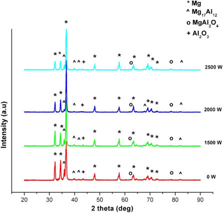
Figure 3. XRD pattern of composites with various UST powers.
Download figure:
Standard image High-resolution image3.3. Composite microstructure
The HR-SEM micrographs showing the dispersion of nanoparticles in matrix material are illustrated in figures 4(a)–(d). Figure 4(a) shows the microstructure of untreated (0 W) composite. It is evident that large-sized clusters of nanoparticles are present in the matrix. This is attributed to the absence of UST during casting. During the mechanical stirring, the nanoparticles tend to form clusters due to agglomeration [7].
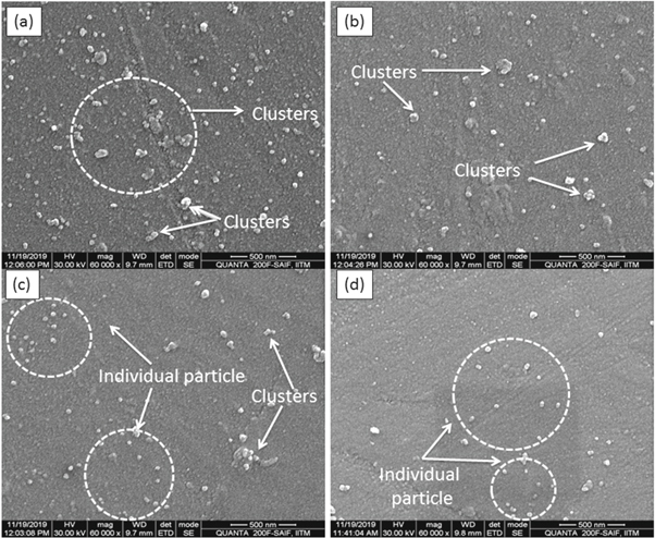
Figure 4. HR-SEM images of composites showing the alumina dispersion: (a) 0 W, (b) 1500 W, (c) 2000 W and (d) 2500 W.
Download figure:
Standard image High-resolution imageFigures 4(b)–(d) shows the effect of UST on the distribution of n-Al2O3 in the matrix. However, the difference in the microstructure can be explained in terms of clusters of nanoparticles due to the variation in the UST power levels. At 1500 W, the clusters are reduced when compared to 0 W composite due to the introduction of UST after mechanical stirring. When the UST power increased, the weak bond part of large clusters broken into tiny clusters due to the impact of high-intensified ultrasonic vibration [14]. Further increase in the power to 2000 and 2500 W effectively reduced the agglomeration by inhibiting the formation of nanoparticle clusters. Also, the uniformity in the distribution increases with increase in the UST power. At 2500 W, more uniform distribution of particles with absence of clusters is evident in figure 4(d). This is due to the propagation of high-intensity acoustic vibration in the composite melt [14, 31].
The high intensity of ultrasonication produced the enhanced heterogeneous nucleation in the composite melt by the cavitation effect. Production of cavities resembled a chain reaction due to the propagation of ultrasonic waves in the melt. Alternate cycles of ultrasonic vibration caused the instantaneous breakdown in the cavitation bubbles; creating high temperature and pressure spots in the composite melt. This high temperature and pressure spots produced large energy in the melt which enhances the wettability between nanoparticles and the matrix [7, 29]. Therefore, most n-Al2O3 particles in the melt became active and formed nuclei in the solidification process leading to easy heterogeneous nucleation upon a slight undercooling [26, 29].
Optical microscope images of the composites were taken for the analysis of the influence of ultrasonic power intensity on grain morphology. Figures 5(a)–(d) shows a significant improvement in grain morphology with an increase in UST power intensity. Composites produced without UST assistance (figure 5(a)) consisted of primary α-Mg and secondary β-Mg17Al12 throughout the matrix with grains coarse and larger in size. In the absence of UST, n-Al2O3 particles clusters were observed in the matrix. This was due to poor wettability and high surface energy of the nanoparticles. With the application of UST, prominent changes were observed in the grain morphology of the matrix. The microstructure of the composites depends mainly on heterogeneous nucleation and fragmentation of coarse grains [19, 23]. At 1500 W UST power, the morphology of coarse semi-continuous net phases does not change because of the smaller level of UST. Further increase in UST power the coarse semi-continuous microstructure became fine and uniform equiaxed grain structure [11].

Figure 5. Optical micrographs of the composites (a) 0 W, (b) 1500 W, (c) 2000 W and (d) 2500 W.
Download figure:
Standard image High-resolution imageFigure 6 shows the grain size of composites relating to the various magnitudes of UST power. The grain size of the untreated composite is seen as 312 μm. At 1500 W of UST power, grain size is reduced significantly. Further, the graph shows a decrease in the grain size with the increase in UST power. The average grain sizes of the composites were 195 μm, 156 μm and 68 μm at 1500 W, 2000 W and 2500 W respectively. The combination of a large temperature gradient with multiple nuclei centres resulted in the fragmentation of primary α-Mg coarse grains into refined equiaxed grains [27, 31, 33]. Undoubtedly, the UST power with the highest intensity (2500 W) resulted in microstructure with reduced grain size.
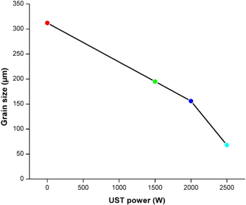
Figure 6. Average grain size of composites with different UST powers.
Download figure:
Standard image High-resolution image3.4. Hardness
Microhardness values of the composites shown in figure 7 depict the significant influence of UST power on the hardness. Initially, the hardness of the untreated composite is 69 VHN. The low hardness of the untreated composite was due to the non-uniform distribution of alumina particles in the matrix due to the mechanical stirring. The formation of clusters in the matrix reduced the hardness. Further, the figure illustrates that the hardness of the composite increases from 69 to 73 due to the introduction of UST. With the application of UST, hardness improved to 73, 76 and 82 VHN at 1500 W, 2000 W and 2500 W respectively. The composite treated with higher UST power exhibited a higher hardness. At higher UST power, the hard reinforcement particles distributed uniformly which increased the capacity of composites for load-bearing. Also, nano-sized hard reinforcement particles restrict matrix deformation by limiting the dislocation movements [25, 37]. Besides, the heterogeneous nucleation and grain refinement due to the presence of fine nanoparticles (25 nm) contributed to the improvement in hardness [28].

Figure 7. Variation of hardness with respect to UST power.
Download figure:
Standard image High-resolution imageImprovement in the hardness of the composites can also be attributed to the contribution of the matrix strengthening effect of reinforcement particles. The strengthening contribution of reinforcements in the matrix is due to various strengthening mechanisms such as load transfer strengthening (∆LT), Orowan strengthening (∆ORO) and coefficient of thermal expansion mismatch strengthening (∆CTE). Among, load transfer strengthening contribution is relatively small when compared to the other two mechanisms and is negligible in the case of nanocomposites due to the low volume fraction [10]. The CTE mismatch strengthening occurs due to the residual plastic strain phenomenon in the composites due to the large difference in thermal expansion coefficients between the matrix and reinforcement. The CTE of AZ91D matrix and alumina reinforcement is 26 × 10–6 °C−1 and 7.4 × 10⁻⁶ °C−1 respectively. Due to the temperature change occurs during the processing, the plastic strain of magnesium matrix around the low CTE ceramic particle enhances the dislocation density and improves the strengthening.
Orowan strengthening is significant in nanocomposites since the inter particle spacing is very less. Zhang and Chen [38] reported that the relative contribution of Orowan strengthening increases with decreasing the size of the nanoparticles. Further, the critical particle size is 5.44 times of the burgers vector of dislocation in the matrix; below which the strengthening contribution by this mechanism is insignificant. The magnitude of burgers vector (atomic diameter) of the magnesium matrix is 0.321 nm. The critical size of the alumina particles in magnesium matrix is likely to be 1.74 nm which is 5.44 times higher than 0.321. Apratim et al [10] reported that the contribution by ∆ORO is significant in UST processed AZ91D/nano alumina (average particle size: 50 nm) composites up to 2 wt%. Nevertheless, ∆CTE has major contribution while ∆LT is negligible. Further, increasing the weight percentage of reinforcement increased the strengthening contribution. In this study, the average particle size is 25 nm which is 14.36 times higher than the critical particle size of alumina in the magnesium matrix. Therefore, the contribution of orowan strengthening is present in the composite in addition to ∆CTE. The improvement in hardness of the nanocomposites can be thus correlated to orowan and grain refinement strengthening offered by the nanoparticles in the matrix by hindering the dislocation movement and resistance to plastic deformation during indentation [37].
3.5. Tensile properties
The tensile properties of AZ91D/n-Al2O3 composites concerning various UST powers are evaluated and illustrated in figures 8(a)–(b). The figure illustrates that assistance of UST during casting of the composite has great influence in the tensile properties of the composites. Figure 8(a) shows the variations in Ultimate Tensile Strength (UTS), Yield Strength (YS) and figure 8(b) shows the percentage of elongation of the composites with different UST powers.

Figure 8. Tensile properties with respect to UST power: (a) UTS and YS, (b) % of elongation.
Download figure:
Standard image High-resolution imageThe tensile properties of the untreated composite are less when compared to the UST assisted composites. From HR-SEM image of untreated composite, it is observed that large clusters of nanoparticles were present in the matrix. The clusters of nanoparticle act as stress concentrator and magnitude of stress is increased drastically while tensile loading [27]. Increase in the UTS from 145 MPa to 187 MPa and increase in YS from 103 MPa to 153 MPa with the increase in UST power from 0 W to 2500 W. This is due to the refinement in the microstructure of the composites that led to a significant improvement in tensile properties with increase in UST power. Improvement in tensile properties is ascribed to (i) the applied UST changed the grain morphology to fine equiaxed which significantly improve the YS and UTS [11, 26]; (ii) Good interfacial bond between n-Al2O3 particles and the matrix. With the high intensity of UST, there was uniform dispersal of n-Al2O3 particles at the grain with a strong intermetallic bond; (iii) higher strength of the hard reinforcement particles leads to the protection of the soft magnesium matrix from localized damage [27]. In addition, a large difference in thermal expansion coefficient values of matrix and reinforcement materials increases the dislocation density and uniformly distributed nanoparticles resist the dislocation movement [14]. From figure 8(b), a slight increase in the % of elongation from 2.4 to 2.7 with respect to increase in UST power is evident. This can be attributed to the obstruction to the formation of fracture by nanoparticles while applying the tensile load [25]. Uniformly distributed nano alumina particles reduced the stress concentration in UST assisted composites compared to the untreated composite. This phenomenon led to an increase in the % of elongation while plastic straining. Also, refined grain structure caused a restriction on crack formation and propagation during tensile loading [14, 27]. Thus, the refinement in grain structure and reduction in porosity due to UST and applied squeeze pressure effectively enhanced the tensile properties of the composites [23, 36].
The fractured surface morphology of the tensile specimens is shown in figures 9(a)–(d). The SEM images of fractured surfaces indicate the occurrence of both brittle and ductile fracture. Straight-line structure present in the morphology of surface is an indication of basal plane slip of magnesium matrix and hence the mode of fracture is brittle [36]. Micro dimples due to the activated non-basal slip system indicate the ductile fracture behaviour of composites. On the contrast, the size and structure of brittle cleavage and micro dimples are different in the images. For untreated composite (figure 9(a)), the cleavage step size is comparatively large and also the presence of flat rough surface indicate the prominence of brittle fracture over ductile fracture [10]. For UST assisted composites the SEM micrographs (figures 9(b)–(d)), show the presence of more micro dimples which indicates the prominence of ductile deformation [21, 22]. The reduction in dimple size and improvement in ductility can be due to applied squeeze pressure during the solidification of the composites in addition to UST [36].
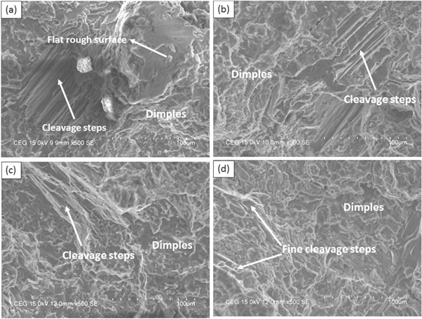
Figure 9. SEM images of broken surface of tensile specimens: (a) 0 W, (b) 1500 W, (c) 2000 W and (d) 2500 W.
Download figure:
Standard image High-resolution image3.6. Tribological properties
The wear rates of the composites as a function of sliding speed under various normal loads are shown in figures 10(a)–(c). The figures depict that with increasing the sliding speed the wear rate decreases. Also, the wear rate of the composites increases with an increase in the normal load. Even though the volume of alumina nanoparticle is same in all composites; the graphs show the significant influence of UST power in wear rate. The figure depicts that, the wear resistance of the untreated composite is poor at all sliding conditions. This was due to the non-uniform distribution of nanoparticles and weak bonding between matrix and reinforcing particle which results in the higher weight loss from the pin surface [37]. The wear resistance of the composite increased when compared to the untreated composite due to the introduction of UST at 1500 W. The wear rate of the composites further decreased with the application of UST power at 2000 and 2500 W. The composite fabricated at 2500 W shows the least wear rate at all sliding conditions. Figure 10(a) shows the wear rate at 12.5 N and various sliding speeds (0.25–0.75 m s−1). Initially, at 0.25 m s−1, the range of wear rate is between 0.011–0.15 mm3 m−1 for all composites. Increasing the normal load from 12.5 N to 25 N increased the wear rate at a range of 0.024–0.027 mm3 m−1 at 0.25 m sec−1 as shown in figure 10(b). Similarly, at a higher normal load of 37.5 N (figure 10(c), the wear rate was in the range of 0.025–0.034 mm3 m−1. However, the wear rate of the composites reduces regardless of the normal load when the sliding speed progresses.
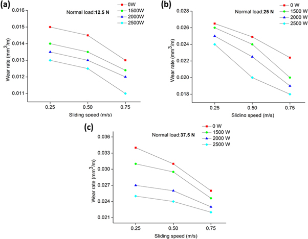
Figure 10. Wear rate at various sliding speeds under normal loads: (a) 12.5 N, (b) 25 N and (c) 37.5 N.
Download figure:
Standard image High-resolution imageThe improvement in grain size and hardness due to the even distribution of n-Al2O3 is the reason for the improved wear resistance of UST composites [39]. UST ensures an even distribution of the n-Al2O3 particles by breaking the distinct clusters with continuous acoustic streaming. The increase in UST power intensity further increases the destruction of clusters and promotes the dispersal of nanoparticles throughout the matrix which is beneficial for better wear resistance of the base material. Also, nanoparticles at the intergranular regions of initially grown grain boundaries inhibit the further grain growth and reduce the grain size. Due to the refined grains, the hardness of the composites improved which further improve the wear resistance [22]. Besides, the uniform distribution of the nanoparticles increases the load-bearing capacity of the composites and protects the pin surface from severe wear damage [36]. The poor wear resistance of composites concerning the increase in the normal load can be attributed to the increased exposure of the pin surface on to the counterface. When the normal load increases the stress induced in the pin also increases which cause wear damage on the pin surface. Thus, the true metallic contact between the pin and counterface increases due to the increase in the applied load [4]. In addition, due to applied normal load and sliding speed, the frictional heating causes an increase in the surface temperature which forms oxide layer in between the mating surfaces [40]. The presence of the oxide layer could prevent the direct metal to metal contact between the pin and counterface; hence the pin surface under the oxide layer is effectively protected from wear damage [39]. The improved wear resistance of the composites with increasing the sliding speed can be correlated to the reduction in contact time and contact pressure between the tribo pair surfaces. At large sliding speeds, the contact between the pin and counterface is comparatively less which further reduces the wear rate [4].
The average COF values corresponding to various sliding conditions are shown in figures 11(a)–(c). The figure shows that the COF decreases with the increase in the normal load and sliding speed. COF of the untreated composite is high at all sliding conditions. This was due to the detachment of agglomerated nanoparticles from the pin surface during sliding. The detached nanoparticles were squeezed in-between the tribo pair surfaces and further abraded on the pin surface which caused an increase in the COF due to third body abrasion [5]. An improvement in the COF values with the application of UST is evident in the figure. COF of the composites increases with the increase in the UST power due to the uniform distribution of nanoparticles. The increased COF value at lower sliding speed is due to the large exposure of the pin surface on the counterface under the action of applied normal load [41]. The COF values decrease with an increase in the sliding speed. As the sliding speed progresses the contact time between the pin and counterface reduces. Thus the COF of the composites decreases with increases in the sliding speed for a given normal load [4]. Further, the improvement in COF is due to the frictional heating at higher normal load and higher sliding speeds. The reduction in COF with increasing the normal load and sliding speed can be attributed to the formation of the oxide layer which effectively enhances the lubrication effect [41]. Besides, the bulk softening and plastic flow due to frictional heating further smoothens the pin surface which leads to a reduction in adhesion between the pin and counterface surfaces [4]. The least COF values were obtained for the composites fabricated at 2500 W power. Therefore, a graphical comparison of friction values as a function of sliding distance (1000 m) registered in the data acquisition system during sliding for the composite fabricated at 2500 W is given in figures 12(a)–(c). The figure confirms that the average COF value of the composites decreases with increasing the sliding speed irrespective of the normal load. Also, COF values decrease as the normal load increases.

Figure 11. Coefficient of friction at various sliding speeds under normal loads: (a) 12.5 N, (b) 25 N and (c) 37.5 N.
Download figure:
Standard image High-resolution image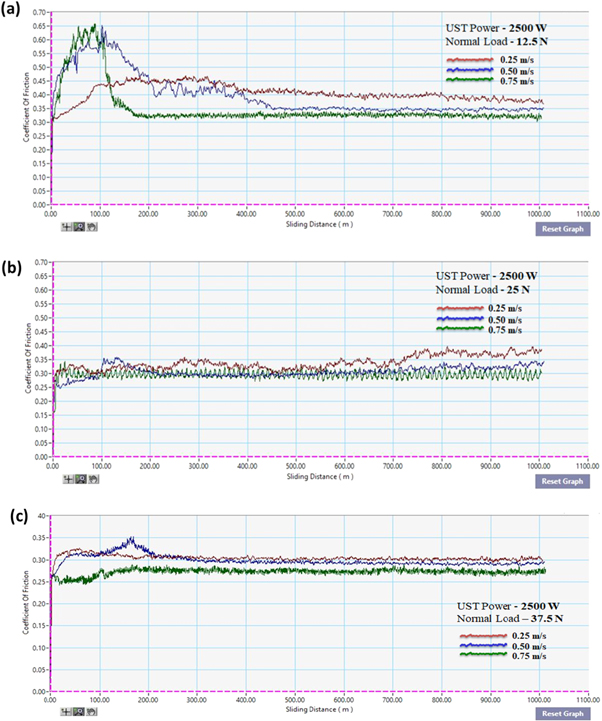
Figure 12. Coefficient of friction of composite (2500 W) as a function of sliding distance at different sliding speeds under normal loads: (a) 12.5 N, (b) 25 N and (c) 37.5 N.
Download figure:
Standard image High-resolution image3.7. Worn surface analysis
The wear mechanisms responsible for the wear behaviour of the composite pins were examined using SEM images of worn surface. Figures 13(a)–(d) shows the images of worn surface of pins at low normal load (12.5 N) and sliding speed (0.75 m s−1). The images show the presence of grooves and scratches in the worn surface which is the indication of typical abrasive wear mechanism. Abrasive wear occurs due to the entrapment of hard asperities between the pin and counterface surfaces [37]. During sliding, the hard asperities make grooves on the soft matrix parallel to the sliding direction which causes material loss from the pin surface. Wide and deep grooves in the SEM image of untreated composite (figure 13(a)) indicates large wear under 12.5 N load. The grooves become narrow and shallow in UST composites. The surface protection offered by the uniformly distributed nanoparticles reduced the wear damage. In addition, magnesium tends to form magnesium oxide (MgO). The oxide particles on the worn surface indicate oxidative wear. However, the oxidation is less due to the low normal load applied. In addition, the presence of prows indicates that adhesive wear is also operative. Grooves with the smoother surface are evident in the images which are due to the adhesive action between the surfaces during sliding [4].
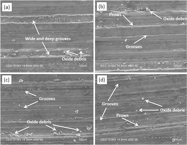
Figure 13. Worn surface analysis of pin specimens at 12.5 N and 0.75 m s−1: (a) 0 W, (b) 1500 W, (c) 2000 W and (d) 2500 W.
Download figure:
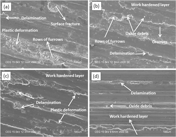
Standard image High-resolution imageSEM micrographs of the worn surface at higher normal load (37.5 N) and maximum sliding speed (0.75 m s−1) are shown in figures 14(a)–(d). The images show the evidence of reduced wear resistance of the composites due to the large applied load. Figure 14(a) shows the worn surface of the pin of the untreated composite. The image shows the presence of surface fracture which occurs due to the detachment of nanoparticle clusters. The UST assisted composites 14(b–d) shows plastic deformation and rows of furrows in addition to abrasive grooves. This indicates the dominance of adhesive wear over abrasion wear. Under the action of higher normal load and sliding speed, plastic deformation on the pin surface occurs which then forms a work-hardened layer which prevents the pin surface from wear loss [4]. The presence of surface cracks and patches indicates the evidence of delamination wear at higher normal load and sliding speed. At this sliding condition, the generation and propagation of cracks leads to delamination of the surface in the form of a thin sheet or flake like structures which revoke the wear resistance. Besides, the presence of more oxide particles on the surface indicates severe oxidation of the worn surface. The oxide particles filled in the grooves improve the wear resistance and enhance the lubrication which in turn decreases the COF of composites [5].
Figure 14. Worn surface analysis of pin specimens at 37.5 N and 0.75 m s−1: (a) 0 W, (b) 1500 W, (c) 2000 W and (d) 2500 W.
Download figure:
Standard image High-resolution image
4. Conclusions
AZ91D/n-Al2O3 composites were successfully fabricated through variations in the power intensity of the ultrasonic treatment process. The physical, microstructural, mechanical and tribological properties of composites fabricated using ultrasonic assistance were compared with those of a composite fabricated without ultrasonic assistance and the following conclusions have been drawn.
- 1.There was a decrease in the porosity of the composites with an increase in applied UST power.
- 2.HR-SEM images showed the presence of clusters of nanoparticles in the untreated composites. With the assistance of UST with various power intensities, the formation of clusters was reduced, and a uniform distribution was achieved at 2500 W.
- 3.Optical micrographs showed a significant refinement in grain structure with an increase in power intensity. The grain sizes measured were 312, 195, 156, 69 μm for 0, 1500, 2000 and 2500 W power respectively.
- 4.Increase in the UST power increased the microhardness of the composites due to the uniform distribution of hard alumina nanoparticles. The hardness of the composite fabricated at 2500 W improved by 18% compared to untreated composite.
- 5.The tensile properties of the composites were improved with an increase in UST power. At 2500 W, YS, UTS and % of elongation of the composites improved by 48%, 28% and 10 % respectively over those of an untreated composite. The SEM images of fracture surface of tensile specimens showed a mixed (ductile and brittle) mode of fracture.
- 6.Tribological properties of the composites improved with increasing the UST power. Wear rate and coefficient of friction of composite fabricated at 2500 W was less at all wear testing conditions. The wear mechanisms responsible for the wear behaviour of the composites were abrasion, adhesion, oxidation and delamination.
Acknowledgments
The authors acknowledge the financial support (Grant number: EEQ/2017/000382) by Science and Engineering Research Board (SERB), Govt. of India.
Conflicts of interests
The authors declare no conflict of interest.