
Abstract
Pure copper is widely used for complex shapes, high thermal conductivity and good conductivity parts, such as heat exchangers, welding nozzles, injection molds, and various conductive parts. However, traditional manufacturing techniques are difficult to design complex pure copper parts into the most effective thermal and conductive structure. Selective Laser melting(SLM) can fabricate parts with complex shapes directly. However, due to the characteristics of easy oxidation, high optical reflectivity and high thermal conductivity, 3D printing pure copper by SLM is extremely challenging. In this study, the feasibility of fabricating pure copper by low-laser energy was studied by both numerical simulation and printing experiments, and the characteristics of the molten pool (molten pool structure, temperature flow and velocity flow) were studied. The results showed that due to its high thermal conductivity, heat spread out quickly in the molten pool, temperature rise rate and cooling rate reached as high as 1.36 × 10⁷ K S−1, 2.99 × 10⁵ K S−1 respectively. And it took only about 1.7 × 10⁻⁴ S for the process time of powder melting and solidification. Additionally, by reducing the particle size, the absorption rate for pure copper was improved, pure copper parts were successfully fabricated with low-laser energy: laser power 500 W, hatching space 0.07 mm, layer thickness 0.03 mm, laser scanning velocity 2500 mm s−1.
Export citation and abstract BibTeX RIS

Original content from this work may be used under the terms of the Creative Commons Attribution 4.0 licence. Any further distribution of this work must maintain attribution to the author(s) and the title of the work, journal citation and DOI.
1. Introduction
At present, there are few studies on SLM forming pure copper parts. The main are listed as below [1, 2]:(1) Pure copper is easy to oxidize, and oxidation greatly affects the performance of SLM forming parts. (2) The laser reflectivity of copper alloy is high, and the reflectivity of powder laser is as high as 96% [3], so higher-power laser is required to completely melt the powder. (3) Pure copper has high thermal conductivity [4], which requires SLM equipment to provide higher energy to compensate for heat loss. Due to the high reflectivity and high thermal conductivity of pure copper powder, it is very important to study the laser energy absorption behavior of pure copper powder. Zhang [5] investigated the relationship between the absorption, distribution of absorbed irradiance within the powder layers, and surface morphology and geometric characteristics. Yan [6] fabricated copper samples successfully by SLM (laser process parameters: linear energy density 0.50 J mm−1, laser power 200 W and 300 W, laser scanning speed 400 mm s−1 and 600 mm s−1). Constantin [7] fabricated pure copper parts successfully with relative density 95 % and smooth surface finishing (Ra = 18 μm) by SLM (laser process parameters: moderate laser power 400 W, laser scanning speed 400 mm s−1, hatch space 0.12 mm, layer thickness 0.03 mm). Yan [6], Constantin [7] showed that low laser power was applied successfully to fabricate pure copper, which is very meaningful, showing that through process adjustment, low laser power can also be used to fabricate pure copper parts, but too slow scanning speed will lead to extremely low forming efficiency. Jadhav [8] fabricated pure copper parts without cracks successfully by SLM ( laser process parameters: laser energy density 700 J mm−3, laser power 800 W and scan speed 400 mm s−1). Imai [9] obtained the optimum laser process parameters for pure copper (laser energy density around 1000 J mm−3, laser power 800 ∼ 900 W and laser scanning speed 300 mm s−1). However, Simply increasing the laser power [4, 8–12] (or reducing the laser scanning speed) will increase the equipment load and will lead to extremely low forming efficiency.
In addition, most of the researches mainly use surface modification or adding elements to form copper alloys to reduce the laser reflectivity and thermal conductivity, and fabricate copper parts successfully. Jadhav [13, 14] enhanced the optical absorption by modifying the surface oxidation of pure copper powder, by which pure copper parts were successfully fabricated at relatively lower laser energy density( laser energy density 463 J mm−3,laser power 500 W and scan speed 400 mm s−1). In addition, Jadhav [15] added 0.1 wt % carbon nanoparticles to pure copper powder to improve the optical absorption and flowability significantly. However, surface modification [13, 14] or adding element to pure copper [15] changed the chemical composition of pure copper, which will inevitably lead to changes the performance (electrical and mechanical properties) of pure copper parts.
In this paper, without changing the chemical composition of pure copper, without surface modification, by reducing the particle size and distribution of the metal powder, adjusting the size of the laser spot, and optimizing the laser process parameters (laser power, scanning speed, layer thickness and hatching space), low-laser energy process for fabricating pure copper by SLM was investigated with numerical simulation and printing experiments, and molten structure, velocity flow and temperature flow were studied systematically.
2. Numerical simulation
2.1. Finite element model of SLM
Figure 1 showed the finite element model of SLM. Considering that the laser reflectivity of pure copper powder is very high, to increase the number of multiple reflections of laser and powder and increase the absorption rate of metal metal to laser (reducing laser reflectivity), this article focused on reducing the particle size of the powder:15 μm–53 μm with random distribution.

Figure 1. Finite element model of SLM.
Download figure:
Standard image High-resolution image2.2. Heat transfer mathematical model
SLM process mainly includes three heat transfer methods: heat conduction, heat convection and heat radiation [16]. Figure 2 showed the SLM heat transfer process.
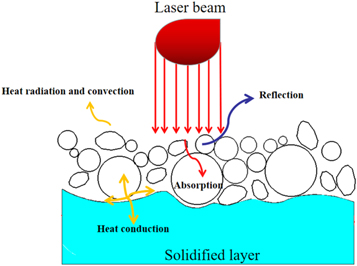
Figure 2. Heat transfer during SLM.
Download figure:
Standard image High-resolution imageFor numerical simulation of SLM, the type of heat Source is critical. The moving Gaussian surface heat source was chosen [3, 17]:
Where, a is laser absorption rate, R is the reflectivity of the material surface to the laser, is the Gaussian beam waist spot radius, K is the radius correction factor.
The heat transfer models during SLM are as below [3, 17]:
Where, σ is the Stephen-Boltzmann constant, ε is the surface emission coefficient, η is the convection exchange coefficient; n is the surface normal direction.
2.3. Thermos-physical properties of pure copper powder
Due to high thermal conductivity and low laser absorption rate, it is hard to fabricate pure copper parts with high dense and fewer defects. To accurately simulate SLM process for fabricating pure copper parts, thermos-physical properties of pure copper were listed in table 1.
Table 1. Thermos-physical properties of Pure copper.
| Property and parameters | Value |
|---|---|
| Density Kg m−3 | 8900 |
| Thermal conductivity W/(m · K) | 377 |
| Specific heat J/(Kg · C) | 386 |
| surface tension coefficient (mN · m−1) | 890 |
| Liquidus temperature (K) | 1357.77 |
| Solidus temperature (K) | 1357.77 |
| Latent heat of fusion (J/Kg) | 211000 |
| Absorptivity coefficient (%) | 44 |
| Contract angle (°) | 90 |
| Temperature sensitivity (mN · m−1 · K−1) | 0.00023 |
2.4. Characteristics of pure copper powder by SLM
For SLM process, thermal conductivity and absorption rate of metal metal to laser are key parameters, which determine the feasibility, forming efficiency and difficulty of SLM forming: Generally speaking, the higher the thermal conductivity, the faster the heat transfer, which causes the heat to be unable to accumulate in the metal powder; the lower the absorption rate of metal metal to laser, the laser energy cannot be converted into heat efficiently.
Take three materials(316L, Zl205A( AlCu5MnCdVA) and pure copper) that we have studied [3, 18–21] as example: 316L SLM forming difficulty is the lowest, ZL205A forming difficulty is very high, and so what about pure copper?
Table 2 showed the comparison of thermal conductivity of 316L, Zl205A and pure copper. Pure copper has the highest thermal conductivity, reaching 377 W m−1·K−1, which is 3.3 times and 23.2 times that of ZL205A and 316L, respectively. Therefore, during the SLM forming, heat cannot accumulate in pure copper for a long time, resulting in a serious decrease in the ability of the powder to absorb heat.
Table 2. Thermal conductivity of 316L, Zl205A and pure copper.
| Materials | 316L | ZL205A | Pure copper |
|---|---|---|---|
| Thermal conductivity | 16.2 | 113 | 377 |
| (W/(m · K)) |
Table 3 showed the comparison of absorption rate of metal metal to laser of 316L, Zl205A and pure copper. Pure copper powder absorption rate is 44%, much lower than 316L stainless steel, but higher than ZL205A. After solidification, the absorption rate decreased significantly to 4%(reflection is 96%), close to mirror reflection.
2.5. Process parameters for FEM
In order to explore the feasibility of fabricating pure copper parts by SLM, the volume energy density is selected as the research object to represent the input energy per unit volume.
Where, laser power P (W), the scanning velocity V (mm s−1), hatching space h (mm), and layer thickness t (mm).
In this paper, on the basis of trial and error printing in the early stage, six representative sets of process parameters were listed, as shown in table 4.
- (1)Scheme NO.1 was used to explore forming difficulty comparison of 316L, Zl205A and pure copper: the same parameters (Scheme NO.1) were applied to SLM forming 316L, Zl205A and pure copper. As shown in figure 4, the characteristics of pure copper preparation was obtained: Smaller Hatching space, lower laser scanning velocity and larger Laser power.
- (2)Based on Scheme NO.1, Scheme NO. 2-No.6 were selected: laser power changed from 300–390–500–900 W, Hatching space changed from 0.07–0.09–0.11 mm, laser scanning velocity changed from 500–1500–2500 mm s−1.
Table 4. Process parameters for FEM.
| Scheme NO. | Hatching space (mm) | Laser Power(W) | Laser canning velocity (m s−1) | Volume energy density (J mm−3) | Remarks |
|---|---|---|---|---|---|
| 1 | 0.11 | 250 | 1500 | 50.50 | Forming difficulty comparison of 316 L, Zl205A and pure copper |
| 2 | 0.09 | 300 | 2500 | 44.44 | Process debugging to obtain the optimized process window |
| 3 | 0.09 | 390 | 2500 | 57.77 | |
| 4 | 0.07 | 500 | 2500 | 95.23 | |
| 5 | 0.07 | 500 | 500 | 476.19 | |
| 6 | 0.07 | 900 | 500 | 857.14 |
3. Results and discussion
3.1. Forming comparison of 316L, ZL205 and pure copper
Figure 3 showed the two-pass forming of three materials(316L,ZL205A,Pure copper) by the same process parameters (table 4 Scheme NO.1): laser power 250 W, laser scanning velocity 1500 mm s−1, hatching space 0.11 mm.
- (1)316L: For Scheme NO.1, the energy density was too high, and the temperature of the molten pool was as high as 4000 K, which exceeded the boiling point and led to vaporization of liquid metal: The recoil pressure made the surface of the molten pool sag badly and splash defects occurred. The simulation process was terminated due to excessive defects.
- (2)ZL205A: For Scheme NO.1, the energy density was appropriate, the surface of the molten pool was smooth and flat, and the overlap between adjacent molten channels was good.
- (3)Pure copper: For Scheme NO.1, the energy density was too small, resulting in part of the powder cannot be completely melted, and the overlapping between molten tracks was too low, and even adjacent molten tracks had no contact.

Figure 3. Two-pass forming diagram of 316L, ZL205A and pure copper for Scheme NO.1:(a) 316L;(b) ZL205A;(c) pure copper.
Download figure:
Standard image High-resolution imageTherefore, it is very challenging to fabricate pure copper parts by SLM process, due to its extremely high thermal conductivity and laser reflectivity. In this paper, pure copper SLM forming process window was obtained, as shown in figure 4: table 4 Scheme NO.4, laser power 500 W, laser scanning velocity 2500 mm s−1, hatching space 0.07 mm.
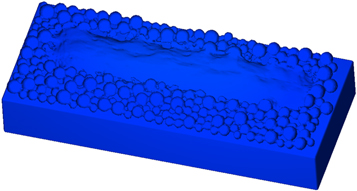
Figure 4. Two-pass forming diagram of pure copper for Scheme NO.4.
Download figure:
Standard image High-resolution image3.2. Molten pool structure,velocity flow and temperature flow for pure copper
3.2.1. Molten pool structure
The molten pool structure showed different structures during the SLM forming process. Authors [3] studied the ZL205A molten pool structure, which was divided into five stages, as shown in figure 5.

Figure 5. The typical molten pool structure.
Download figure:
Standard image High-resolution imageIt should be noted that by adjusting the process parameters, the five-stages molten pool structure will not all appear. Figure 6 showed the molten pool evolution of the pure copper by Scheme NO.4: double-concave structure, protruding structure and ideal plan structure.
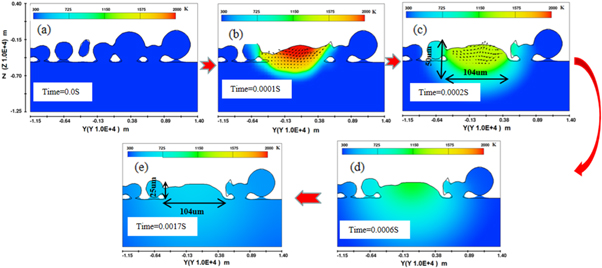
Figure 6. Molten pool structure evolution for Scheme NO.4.
Download figure:
Standard image High-resolution imageFor Scheme NO.4, obvious deep-concave structure did not appear, which meant process parameters of Scheme NO.4 ensured that suitable temperature(exceed the melting point 1357 K, but lower than boiling point 2799 K) of the molten pool: suitable temperature avoided defects such as incomplete powder melting,and avoided metal vapor recoil pressure leading to uneven surface topography of the molten pool.
In addition, as shown in figure 6(c), molten pool size was about 104 μm × 50 μm. After complete solidification, the molten track size was about 104 μm × 25 μm.
Figure 7 showed two-pass molten tracks for Scheme NO.4 (hatching space 0.07 mm), The overlapping between molten tracks was smooth, no porosity. The single molten pool width was about 110 um, and the two-pass molten tracks width was 179 um, so the molten pool overlap rate was approximately 37%, which met the the requirements of most suitable overlapping rate around 30% [24].

Figure 7. Overlapping of two-pass molten tracks(Scheme NO.4).
Download figure:
Standard image High-resolution image3.2.2. Evolution of temperature flow in molten pool
For SLM, metal powder goes through two processes: melting and solidification, but the duration is extremely short, a few milliseconds or even less. Laser moves very fast, up to 5000 mm s−1, and the heating and cooling rates inside the molten pool can reach 105 k s−1. However, temperature flow and velocity flow of the molten pool determined the final quality of the molten pool and the final quality of the forming part. Therefore, analyzing temperature field and velocity field helped to obtain relationship between laser process parameters and product quality.
Pure copper belongs to crystal, its melting point and solidification are both 1357 K. Figure 8 showed the temperature evolution on the surface of the molten pool. The temperature roes rapidly to melting point temperature 1357 K at 1.2 × 10⁻⁴ S(Point A), and the temperature rise rate reached 1.36 × 10⁷ K S−1. For the process time of powder melting and solidification(Point A to Point C), it took about 1.7 × 10⁻⁴ S. After complete solidification (Point C), temperature dropped to 400 K at 0.0035 S, when the cooling rate reached 2.99 × 10⁵ K S−1.
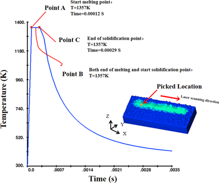
Figure 8. The temperature evolution law during SLM.
Download figure:
Standard image High-resolution imageFigure 9 showed the temperature colour contour line during SLM. The colour indicated the magnitude of the temperature, and the isotherms temperature difference was 212 K. As shown in figure 9(a), it was interesting that the temperature gradient on the surface is less than that inside molten pool: temperature gradients in the surface and bottom of molten pool were about 1.7 K um−1, 10.7 K um−1 respectively. This is mainly due to the fact that the heat conduction of liquid to powder is lower than that of solid to powder. Figure 9(b) showed the temperature colour contour line of longitudinal 2D slices of molten track. The temperature gradient at the front of the molten track was greater than that at the back end of the molten track, and similar to that at the bottom of the the molten track: the temperature gradients at the front, back end and the bottom of the molten track were approximately 74 K um−1, 9–10 K um−1, 70 K um−1 respectively.
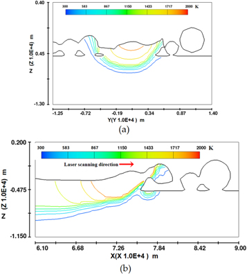
Figure 9. Temperature flow of molten pool and molten track (a) Cross 2D slices of molten pool; (b) Longitudinal 2D slices of molten track.
Download figure:
Standard image High-resolution imageCompared with figures 9(a), (b) showed temperature flow in cross section of molten pool, which affected the molten pool width, which determined the hatching space and molten track overlapping. In addition, the temperature distribution in cross-section was almost symmetrical, but due to the forward movement of the laser beam in the longitudinal section, the temperature gradient between the front end and the rear end was quite different.
The difference of temperature gradient in molten pool directly ledss to the difference of heat expansion and cold contraction, which is one of the reasons for the cracks of SLM forming pure copper parts. Therefore, it is a very effective method to reduce SLM forming cracks by preheating the bottom substrate, which helps to decrease the difference of temperature gradient.
3.2.3. Evolution of velocity flow in molten pool
Figure 10 showed the velocity evolution on upper surface of molten track. It is interesting to find that Point A, Point B and Point C in figure 10 is similar to that in figure 8, which showed that the velocity and temperature flow were closely related and affected each other. From 0 to Point B, molten metal flowed back with maximum velocity 0.26 m s−1 in -X direction.

Figure 10. The velocity evolution law.
Download figure:
Standard image High-resolution imageFigure 11 showed the velocity flow in longitudinal section: the color indicated the magnitude of velocity, the arrow indicated the velocity direction. The molten metal flowed back, and the velocity reached 2.49 m s−1( similar to laser scanning velocity 2.5 m s−1).

Figure 11. Velocity flow of molten track.
Download figure:
Standard image High-resolution imageMore importantly, surface smoothness s is one of the intuitive indicators to judge the laser process parameters, and the speed difference among the upper surface determined the smoothness of molten track. As shown in figure 11, molten track had relatively uniform speed in the molten stage of the surface, which guaranteed the smoothness of the solidified surface at the back end.
3.3. Experimental printing
3.3.1. Laser process window for pure copper
In order to ensure the accuracy and reliability of the simulation, pure copper experiment printings by SLM were carried out. Figure 12 showed the morphology of pure copper samples fabricated by SLM of Scheme NO.2-5.
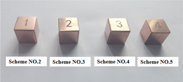
Figure 12. Samples fabricate by SLM of Scheme NO.2-5.
Download figure:
Standard image High-resolution imageAs shown in figure 13, densities of forming samples were between 5.506 Kg/m3 and 6.22 Kg/m3. For Scheme No.1, too larger hatching space led to smaller overlapping between molten tracks and fail forming. For Scheme No.6, too low laser canning velocity led to too high laser energy density, pure copper powder over-burned and failed forming.
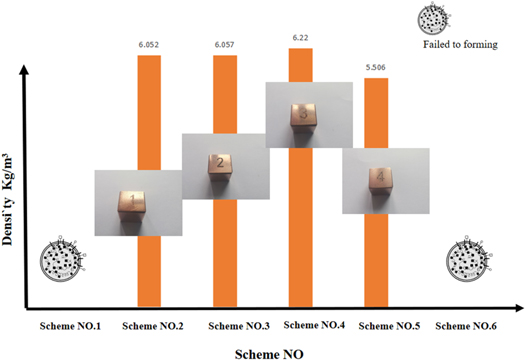
Figure 13. Samples density of Scheme NO.1-6.
Download figure:
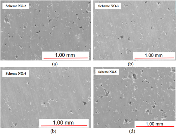
Standard image High-resolution imageFigure 14 showed morphology of upper surface for Scheme NO.2-5 after polishing by SEM (Hitachi SU8010). Although after several times of process debugging, internal pore of samples were still very serious, which was mainly due to extremely high thermal conductivity and laser reflectivity. So fabricating pure copper parts without pores and cracks by traditional SLM (1064 nm infrared laser) was very challenging.
Figure 14. Morphology of Supper surface of Samples of Scheme NO.2-5.
Download figure:
Standard image High-resolution image
Considering that the absorption rate of 532 nm green laser is higher than that of 1064 nm infrared laser, especially for conductive materials such as pure copper, and the difference is particularly obvious. Therefore, the new SLM technology called Green SLM Technology has the potential to fabricate pure copper parts, which is a key direction of our next research.
As shown in figures 13, 14, choosing pores as the quantification standard, the process window for pure copper by SLM was obtained as below: laser power P = 500 W, scanning speed V = 2500 mm s−1, hatching space H = 0.07 mm.
4. Conclusions
In this paper, the characteristics and comparison of 315L, ZL205A and pure copper were analyzed, which gave the reasons why it is very challenging to fabricate pure copper parts by SLM. By reducing the particle size, which increased the number of multiple reflections between laser and powder, the absorption rate of metal metal to laser was increased. On this basis, pure copper parts were fabricated successfully with low-laser energy.
- (1)Choosing pores as the quantification standard, process window for pure copper by SLM was obtained: laser power P = 500 W, scanning speed V = 2500 mm s−1, hatching space H = 0.07 mm. Low laser power and faster laser scanning speed not only reduce the requirements of laser equipment, but also improve the efficiency of SLM forming.
- (2)Compared with ZL205A [3], three structural forms (double-concave structure, protruding structure and ideal plane structure) appeared during SLM.
- (3)When the laser applied on the metal powder, the heating rate reached up to 1.36 × 10⁷ K S−1; For pure copper, it took only about 1.7 × 10⁻⁴ S for the process time of powder melting and solidification.
And, the authors [18] has systematically studied the two-step remelting process, which increases the ultimate tensile strength and yield strength of 316L stainless steel to 725 MPa and 643 MPa. Unfortunately, since the absorption rate of the solidified copper plate to the laser is only 4%(almost mirror reflection), it is interesting that the second-step laser remelting can hardly melt the pure copper plate. Of course, it is meaningful that the second-step laser remelting can be used for surface modification, but not remelting, which is the focus of our next research.
Funding
This research was funded by Zhejiang Institute of mechanical and Electrical Technology science and education integration project(A-0271-19-005), the key Research Project of Natural Science of Anhui Province (KJ2019A1157); Outstanding talents cultivation project in Anhui province in 2019(gxgnfx 2019100).
Conflicts of interest
The authors declare no conflict of interest.