Abstract
Titanium oxide-based photocatalytic filters were produced by Fused Deposition Modelling (FDM) using biopolymers obtained from renewable biomass resources. The thermoplastic route allows shaping composites through the immobilization of photoactive TiO2 nanoparticles in an environmentally friendly bioplastic such as the polylactic acid (PLA). Composites with an inorganic charge of 30 wt% of TiO2 nanoparticles (NPs) exhibit a 100% methyl orange (MO) degradation after 24 h of light exposition due to the extremely uniform dispersion of the nanophase within the polymer matrix in the FDM feedstock. Surface modification of TiO2 NPs allows the optimization of the colloidal dispersion and stabilization of the inorganic charge in a PLA solution and hence, the optimal distribution of nano-photoactive points in the TiO2/PLA filaments and scaffolds. The proposed new route of processing improves the dispersion of nano-charges comparing with the traditional thermo-pressing routes used for mixing thermoplastics based composites, avoiding the thermal degradation of the polymer and providing a customised product. In this manuscript the evolution of photodegradation with the increase of TiO2 content in the composite and the variation of the filter geometry was evaluated.
Export citation and abstract BibTeX RIS

This is an open access article distributed under the terms of the Creative Commons Attribution 4.0 License (CC BY, http://creativecommons.org/licenses/by/4.0/), which permits unrestricted reuse of the work in any medium, provided the original work is properly cited.
Energy and environmental issues are among the most dramatic and urgent challenges that modern society has to face. Realizing that, researchers are spending lot of effort on more eco-friendly alternative technologies for many daily life areas. Among them, sustainable energy production and pollutant removal are two of the areas in which intense research is being carried out. Semiconductor-assisted photocatalysis (mainly based on Titanium dioxide, TiO2) is a well-established technique for water and air pollutants degradation. It is recognized as a predominant advanced oxidation process (AOP) thanks to its efficiency and eco-friendliness.1,2 In particular, AOP techniques of water purification mainly rely on the generation of *OH radicals and their homogeneous attack on organic molecules. About the latter, the spectrum of compounds that are susceptible to this approach includes dyes, pesticides, cosmetics, and more. TiO2, owing to its characteristics, is the most frequently used photocatalyst in water purification processes. It is relatively cheap, water insoluble, non-toxic and highly resistant to different chemicals. In the anatase form, it shows also the highest photocatalytic activity and resistance to so-called anodic photocorrosion. However, the application of TiO2 in form of suspended powder in contaminated water requires further additional operations for the separation after photocatalysis. To avoid this relevant technological inconvenience, several solutions are proposed, which enable the photocatalyst to be immobilised. The TiO2 immobilization on various substrates is an interesting research area within the photocatalytic water treatment field.3 Furthermore, there are additional advantages achievable such as increasing the absorption properties,4–6 and surface hydroxyl groups or reducing the charge recombination.7
Immobilization of TiO2 can be done on powder and pellet substrates,4–6 on rigid/thick substrates or on soft/thin materials.8–14 Some examples of powder/pellet substrates include activated carbon,5 magnesium-aluminum silicates6 and volcanic ash.4 The deposition of fine TiO2 powder on rigid glass surfaces is a quite accepted method. It is commonly accomplished by the simple coverage of the surface with water suspended titania powder and the relative drying. The as-prepared films strongly adhere to the glass due to TiO2 electrostatic charge (the glass surface is usually negatively charged). TiO2 immobilized on soft substrates are normally referred as TiO2 films, membranes or filters. Some examples include TiO2 immobilized on porous Al2O3,9–11 glass filter,13 polyvinylidene difluoride,12 sponge8 and cellulose fibres.14 Various techniques, such as electrospinning,13,14 film casting,12 chemical vapour deposition,10,11 slip and dip-coating,9 have been investigated to achieve the TiO2 immobilization on soft substrates. Although many efforts have been spent to develop these functional filters, further research work is still needed to better understand both their operation and design. The latter is an important aspect in order to produce highly performing devices because it can produce, for e.g., fluid flux enhancements or fouling mitigation. The mentioned filter production techniques, such as slip or dip-coating, allow producing membranes with simple geometries, mainly with planar configuration. Thus, in order to overcome this limitation, we considered Additive Manufacturing (or three-dimensional printing) as a promising shaping technique.
Since the first technique for 3D printing became available in the late 1980s and was used to fabricate models and prototypes,15 AM technology has experienced more than 20 years of development and today is one of the rapidly developing advanced manufacturing techniques in the world due to its process flexibility, its ability to create complex structures and rapid response to design alterations. The 3D printing term indicates a class of technologies such as stereolithography (SLA), selective laser sintering (SLS), syringe extrusion, fused deposition modeling (FDM)/fused filament fabrication (FFF), etc. FDM is the one where a temperature controlled head extrudes a thermoplastic material (at temperatures above its glass transition temperature, Tg) layer by layer. In this process, the material changes from a solid to a semi liquid state during the extrusion process and follows the path of a computer aided system.16 The common materials used in FDM process are acrylonitrile butadiene styrene (ABS),17 polycarbonate (PC), poly lactic acid (PLA), polyvinyl alcohol (PVA), etc.18 However, it is well-known that one way to lend active chemistry to 3D printed thermoplastic objects is to incorporate inorganic nanoparticles into the polymer filaments. In this way, FDM technology was found to be a potential method for the fabrication of electronic sensors based on conductive carbon black filled poly (caprolactone) (PCL) filaments.16,19 Carbon nanotubes have been used to reinforce thermoplastic polyurethane filaments and to induce electrical conductivity.20–22 Finally, there has been interest to design and fabricate filaments and then devices, for space-based applications.16,23,24
Although recent works on TiO2-polymer nanocomposites, especially for biodegradable implants applications,25,26 can be found in literature, up to our knowledge there is no 3D TiO2-based composites where the amount of the inorganic nanophase exceeds 5 wt%. In this paper, we focus on the fabrication and characterization of composite filaments for FDM production of 3D photocatalytic filters. In this environmental friendly approach we selected PLA as polymer matrix, since it is a biopolymer obtained from renewable biomass resources, to have fashioning complex shaped photocatalytic filters. The TiO2-PLA filaments were initially prepared with 15–30 wt% of TiO2 nanoparticles (NPs) and tested in the photodegradation of methyl orange (MO) to demonstrate its photocatalytic activity.
Materials and Methods
All chemicals were of reagent grade and used without any further purification. The as-received TiO2 nanopowder (Aeroxide P25, Evonik Degussa GmbH, Germany) with a density of 4.2 g/cm3, a specific surface area of 50 ± 15 m2/g and an anatase:rutile ratio of 80:20, was dispersed in deionized water to prepare a stable TiO2 water-based suspension formulated with a 6 vol.% of solid content by adding 6 wt% (referred to powder) of a stabilizer such as the branched polyethylenimine (PEI, pKa 8.6, Mw 25,000 mol/g, Aldrich, Germany) at pH 8. Modified TiO2 NPs by PEI coverage in suspension were then ball-milled for 90 minutes (using Al2O3 balls of 1 cm in diameter) and subsequently centrifuged at 4000 rpm for 15 minutes in order to remove the aqueous solvent.
The procedure used for the particles dispersion and the adsorption of PEI onto the NPs surfaces has been described previously elsewhere.27 However, to improve the centrifugation of well dispersed NPs, the conditions for the suspension coagulation were stabilised. In this sense, the modification of the zeta potential for TiO2 NPs induced by the absorption of PEI was determined in a wider pH range (2–12) using the laser Doppler velocimetry technique in a ZetasizerNano ZS (Malvern, UK), and then compared to zeta potential determination in a similar pH range for the bare nanopowder. The pH adjustment of the suspensions was carried out by addition of small quantities of 0.1 M HNO3 or Tetramethylammonium Hydroxide (TMAH) and controlled with a pH probe (Metrohm AG, Germany). The particle size distribution of the PEI- TiO2 NPs was also characterized by Dynamic Light Scattering (DLS) by using the ZetasizerNano ZS (Malvern, UK) for concentration ranging between 0.001–0.1 g/L. All the mentioned suspensions were sonicated before each measurement using a UP400S Ultrasonication probe (Hielscher, Germany) for an optimized period of 30 s.
Two different compositions of PLA:TiO2 (85:15 and 70:30) were prepared by mixing a specific amount of the modified PEI-TiO2 NPs (still wet after centrifugation) with a certain volume of a polylactic acid (PLA) solution, that was prepared at 80 g/L dissolving, at 40°C under magnetic stirring, polymer pellets (PLA 2003D with D-isomer content of 4.25% provided by Natureworks (USA) in tetrahydrofuran (THF, Panreac Germany).
A vigorous mechanical stirring step coupled with a US treatment (30–60 seconds) were applied to obtain a homogeneous mix which was loaded in a conventional rotary evaporator to remove THF under reduced pressure. The resulting powder was completely dried in a laboratory stove at 80°C and milled later in a blade grinder to reduce the PLA:PEI-TiO2 granules size. The latter were extruded at temperatures ranging 185–187°C using a homemade single screw extruder to manufacture FDM filaments with a suitable diameter (2.5–3 mm). The morphology and shape of the modified PEI-TiO2 NPs, the PLA:PEI-TiO2 composite granules and, finally, the filaments were examined by a field emission scanning electron microscope (FESEM Hitachi S-4700, Japan).
The extruded filaments were employed for manufacturing scaffolds by FDM using a conventional 3D printer (Prusa I3 with the Repetier software) with a nozzle diameter ranging between 0.3–0.5 mm. These filters were designed with a CAD software and printed varying parameters such as: filter diameter (10, 14 and 2 mm), scaffold height (number of printed layers: 4 or 8) and the infill (20–40%). The bed and nozzle temperatures were fixed at 55 and 185°C respectively, with a filament feed rate of 40 mm/s. The printed filters were characterized by a Tabletop Scanning Electron Microscope (SEM, Hitachi TM-1000).
Thermogravimetric Analysis (TGA) (Perkin Elmer, USA) was used to study the thermal evolution of the PLA:PEI-TiO2 composites. Tests were performed in air atmosphere with a constant heating rate of 5°C/min up to 600°C. The identification of the crystal phases of the samples was carried out by X-ray diffraction (XRD) with a Siemens D5000 diffractometer (Germany) with a Kristalloflex 710 generator (Kα(Cu) λ = 1.5405 Å; 40 kV; 30 mA; 2θ = 5–70).
Finally, the photocatalytic activity of the scaffolds was evaluated by the degradation of methyl orange (MO) in aqueous solution.28 The used light source (Oriel, model 96000) is equipped with a solar light simulating Xe-arc lamp (Osram XBO 450 W) with commercial AM 6197 filter. The tests were performed using 25 mL of MO aqueous solution with a concentration of 3 mg/L. The pH of the solution was adjusted to 2 using HCl. The quartz reactor vessel was plugged to prevent MO solution evaporation. First, photolysis and dark tests (adsorption) were performed to confirm that the MO degradation is only associated with the PLA:PEI-TiO2 scaffolds and not to light irradiation and/or adsorption. Photocatalytic measurements were performed introducing the PLA:PEI-TiO2 scaffolds in the MO solution that was maintained under continuous stirring and irradiation. Degradation phenomena were monitored using a home-made system described previously elsewhere.28 A narrow bandpass filter centered at 500 nm and bandwidth of 10 nm (Thorlabs, FB-500-10 full width at half maximum) was placed in front of a biased Silicon Photodetector (Thorlabs DET100A). The filter limits allow the light transmission in a wavelength range that matches the absorption band of MO (508 nm). Therefore, the intensity of light at the detector allows measuring the degradation of MO. All the elements were installed on an optical table to ensure stability and also, optically isolated in the dark to avoid the presence of other light sources. The output signal from the detector (voltage) was sent to a Keithley 2010 multimeter where it was recorded every 10 min using a Visual Basic homemade code.
Results and Discussion
The stabilization of TiO2 NPs in deionized water was firstly examined through zeta potential measurements. Figure 1a shows the variation of the zeta potential as a function of pH for bare NPs and also for NPs covered with the polyelectrolyte PEI as dispersant additive (PEI-TiO2). Two zones of maximum stability were displayed in the curve corresponding to the bare TiO2, where the surface charge is enough to provide repulsive interactions among the particles, far from the isoelectric point (IEP) located at pH 7. One zone was located at acid pH (2–4) with zeta potential values close to +40mV and the other at basic pH (8-12) with values ranging from −30 to −50mV. Although the surface charge balance of NPs was slightly higher at other pH values, the working pH was fixed in at 8 for the PEI adsorption, since it is more efficient in these conditions. The PEI used is a branched chain with primary, binary and ternary amino groups that maintains highly protonated (charged) at pH 8 favouring the additive adsorption on negative TiO2 surfaces. Consequently after PEI addition, the PEI-TiO2 suspension (at pH 8) exhibits a zeta potential of +66 mV, due to the adsorbed protonated PEI, and a shear-thinning behavior with a manageable viscosity of 70 mPas (at shear rate of 100 s−1).27
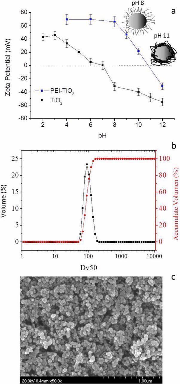
Figure 1. (a) Evolution of the zeta potential of bare-TiO2 and modified PEI-TiO2 NPs in aqueous suspension varying the pH (2<pH < 12); (b) Size distribution of the modified PEI-TiO2 NPs and; (c) FESEM image of the modified PEI-TiO2 NPs.
Moreover, the DLS measurements were also performed to determine the particle size after the surface modification. Figure 1b shows the particle size distribution of the PEI-TiO2 NPs where one narrow peak, centred on 120 nm (DV50) was observed as additionally confirmed by the cumulative volume % curve. Despite the high dispersion obtained, the modified particles presented a slight trend to the agglomeration as confirmed by the BET diameter (DBET). This parameter is calculated from the powder morphological properties, specific surface area, SSA, and density, ρ, (DBET = 6/ρ·SSA), and allows the evaluation of the effect of the polyelectrolyte on the particles dispersion. A value of DBET close to 30 nm was obtained, which means that the PEI-TiO2 NPs presented a relatively low agglomeration factor of 3 (Fag = DV50/DBET). Figure 1c shows the morphological characterization of the modified powder by FESEM that confirms the presence of small particles agglomerates around 100–150 nm. Although the size of the TiO2 agglomerates maintains in the nanometric range, the dispersion of TiO2 in the PLA matrix could be limited which can affect the photoactive efficiency of the 3D printed pieces.
The variation of the zeta potential as a function of pH was also examined after PEI adsorption at pH 8. The global charge balance at the particle surfaces was completely modified appearing positive up to pH 11 after which the surface charge became negative. The variation of zeta potential induced by the PEI on the TiO2 NPs can be explained by the way in which the polyelectrolyte chain interacts with the particle surface (through tail or train conformations), which depends on its pKa value, ionic strength, used solvent or molecular architecture.29 The amino groups of the PEI structure present a high degree of ionization when the working pH<pKa (tail) and a lower degree when the working pH>pKa (train). The sketches in Figure 1a illustrate both configurations. The zeta potential value of the PEI-TiO2 at pH 8 was +66 mV while the increase of the pH toward higher basic values reduced the global charge, neutralizing the surface, to achieve the IEP of the system, where NPs are unstable and the system should coagulate.
In order to prepare the polymeric nanocomposite or feedstock for the extrusion of PLA/PEI-TiO2 filaments,30 the TiO2 NPs were firstly stabilized in aqueous suspensions by the addition of PEI, and then flocculated by varying the pH up to 11 to centrifuge them. The formation of TiO2 agglomerates (100–150 nm), as well as its low zeta potential at pH 11, favours TiO2 NPs flocculation and centrifugation. The wet flocculated PEI-TiO2 nanopowder was then mixed and re-dispersed in the PLA solution in THF under mechanical stirring. Figure 2a shows a scheme of the complete process. The as-prepared PLA/PEI-TiO2 suspension was then gently dried under reduced pressure obtaining PLA/PEI-TiO2 composite granules which were grinded in a blade grinder to reduce their size and to adapt them to the extruder conditions. These granules were then extruded in a single screw extruder with a thermal pass of only 10 cm at temperatures ranging from 185–187°C, obtaining composite filaments with homogeneous diameters lower than 1.75 mm, which were used as the PLA/PEI-TiO2 composite feedstock for printing. Figure 2b displays the pictures of the obtained composites, both powder and filaments, for a specific composition of 85:15 (wt/wt) PLA:PEI-TiO2.
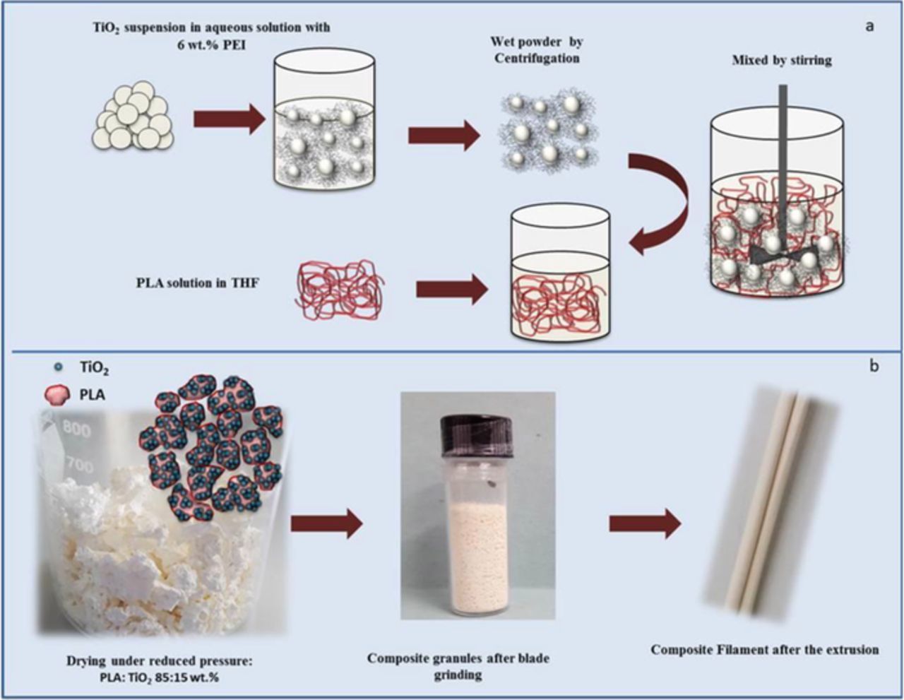
Figure 2. (a) Scheme of the process for the preparation of modified PEI-TiO2 suspension in PLA and; (b) Pictures of the resulting dried composite, PLA/PEI-TiO2 granules, after and before blade grinding as well as the composite filament after the extrusion.
In deep microstructural analysis of the granules, filaments and scaffolds were also characterised by FESEM. Micrographs in Figures 3a and 3b show a low magnification image of a PLA/PEI-TiO2 granule, where the inorganic nanoparticles (white arrows) are just slightly agglomerated but homogeneously distributed in the blend surrounding PLA (blue arrows). This well dispersed composite makes PLA/PEI-TiO2 granules suitable candidates for the production of FDM filaments with an isotropic composition. Figure 3c shows an image of the cross section of an extruded filament (185–187°C) which fulfils the requirements for printing. Although the appearance of the fracture surface is mostly plastic due to the high percentage of the polymer (85:15 (wt/wt) PLA:PEI-TiO2), NPs agglomerates of 100–150 nm, still visible at such magnification, appear to be well-distributed inside the filament (white arrows). The PEI-TiO2 NPs distribution in the PLA matrix is retained after printing at 185°C. The micrographs of the PLA/PEI-TiO2 scaffold in Figure 3d display the dense structure of the rods with inorganic NPs distributed both at the rod surfaces and inside parts.
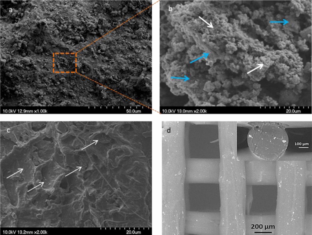
Figure 3. (a, b) FESEM images of the PLA/PEI-TiO2 granules at different magnifications, where blue and white arrows point to the PLA and TiO2 aggregates, respectively; (c) FESEM image of the cross section of a PLA/PEI-TiO2 filament and; (d) SEM image of the top view of a filter including (inset) the detail of the rod cross-section. All images correspond to the composite 85:15 (wt/wt) PLA:PEI-TiO2.
Figure 4a shows the XRD spectra of the 85:15 (wt/wt) PLA:PEI-TiO2 granules and scaffolds. The pattern of the granules is characteristic of a mixture of TiO2 and a crystalline polymer, where the diffractions at 20.7° and 22.9° indicate the presence of the α-phase of PLA (Figure 4b).31 The diffractogram of the scaffold shows the presence of amorphous PLA (from the wide band at 20°) derived by the thermal treatments during the extrusion and printing processes. On the other hand, the TiO2 phase maintains in both cases the expected ratio of anatase and rutile 95% and 5%, compatible with the P25 nanopowder composition. These results evidence the effect of TiO2 NPs as nucleant agent for the polymer matrix. When the composites are processed from the stable suspension of PEI-TiO2 NPs in a PLA solution in fact, the excellent dispersion of PEI modified TiO2 NPs induces the precipitation of pure crystalline PLA over the inorganic seeds during drying.32 However, for the extrusion process, the PLA-TiO2 granules are melted and then deposited: the XRD analysis clearly shows that the polymer preserved the amorphous state after solidification. PLA is in fact a biopolymer that does not crystallize from melting and therefore the thermal processing erases the matrix crystallinity.
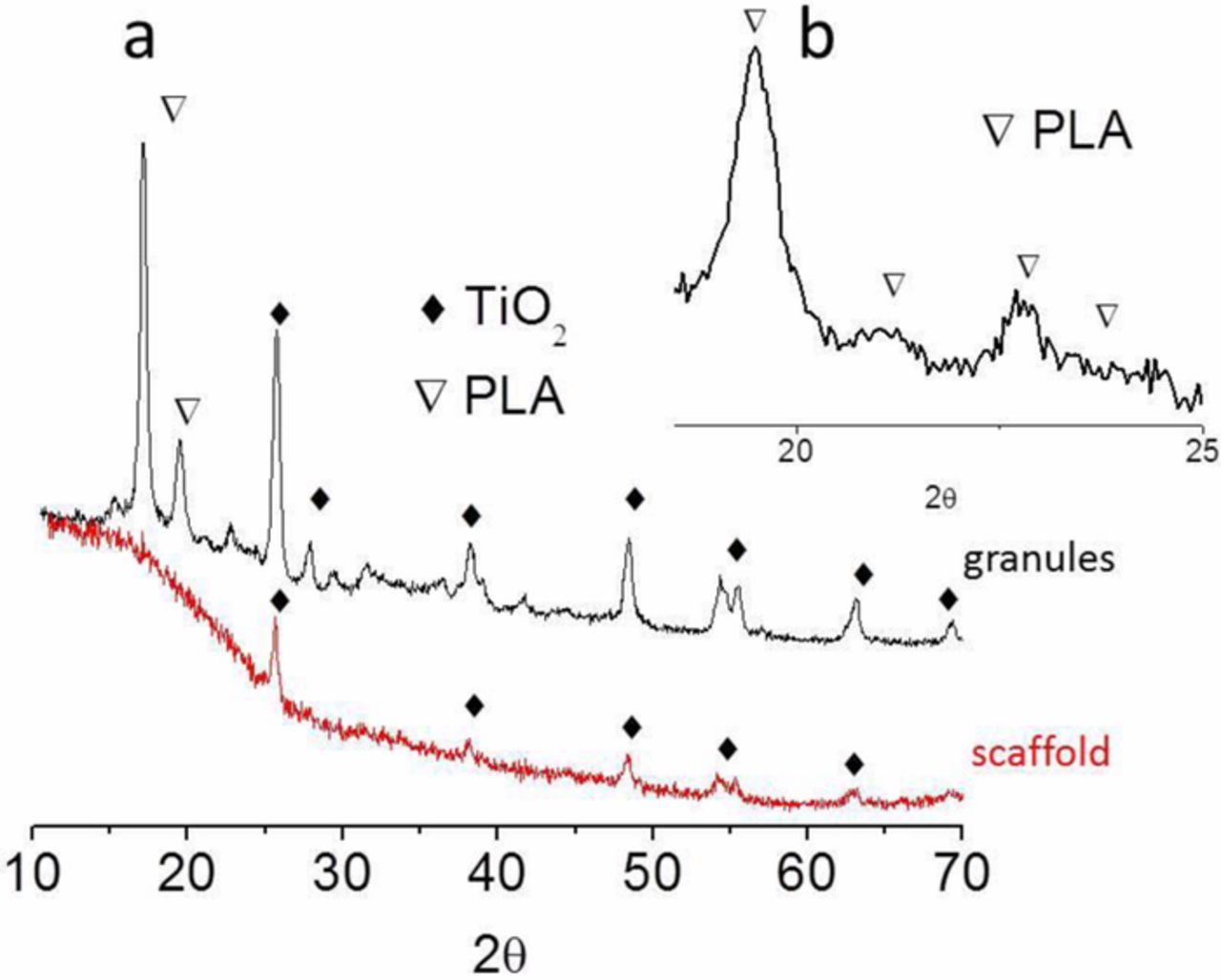
Figure 4. (a) XRD spectra of the granules and scaffold of the composite 85:15 (wt/wt) PLA:PEI-TiO2 and; (b) detail of the peaks associated with the α crystalline phase in the granules scanning.
Two different PLA/PEI-TiO2 composites were used to prepare the feedstock granule-like: 85:15 and 70:30 (wt/wt PLA:PEI-TiO2), labelled respectively 15TiO2 and 30TiO2. The same printing parameters (a printing nozzle of 0.5 mm in diameter, a filament feed rate of 40 mm/s and, a bed and nozzle temperatures of 55 and 185°C respectively), were used to produce different filters designs: in particular filters with diameters of 10, 14 and 20 mm, heights of 4 or 8 layers and, infills ranging 20–40% (which defines the free space left on the designed piece). Table I summarizes the most relevant printing conditions while Figure 5 shows the CAD printing shapes corresponding to the explored printing parameters: scaffold diameter, number of layers and infill. Table I also includes the calculated dimensions of the scaffold: height and the height x length of the structure holes, (considering the CAD models which define the number of bars and holes of the designed scaffold structure, the nozzle diameter (0.4 mm) which define the diameter of the printed bars), the diameter of the filter (10, 14 and 20 mm) and the number of layers (4 and 8 layers).
Table I. Summary of the PLA/PEI-TiO2 filters characteristics processed by FDM.
| Filter | Label | Diameter (mm) | Number of layers | Infill (%) | Height* (mm) | Hole dimensions* (mm): height × length | Weight (g) |
|---|---|---|---|---|---|---|---|
| F1 | 10 | 8 | 40 | 3.2 | 0.4 × 0.80 | 0.12 | |
| F2 | 14 | 4 | 30 | 1.2 | 0.3 × 0.40 | 0.13 | |
| 15TiO2 | |||||||
| F3 | 14 | 4 | 25 | 1.2 | 0.3 × 0.75 | 0.11 | |
| F4 | 14 | 4 | 20 | 1.2 | 0.3 × 0.96 | 0.08 | |
| F5 | 10 | 8 | 40 | 3.2 | 0.4 × 0.80 | 0.12 | |
| F6 | 30TiO2 | 14 | 4 | 40 | 1.6 | 0.4 × 0.73 | 0.14 |
| F7 | 20 | 4 | 40 | 1.6 | 0.4 × 0.82 | 0.18 |
*Calculated dimensions considering printing design parameters and CAD models in Figure 5.
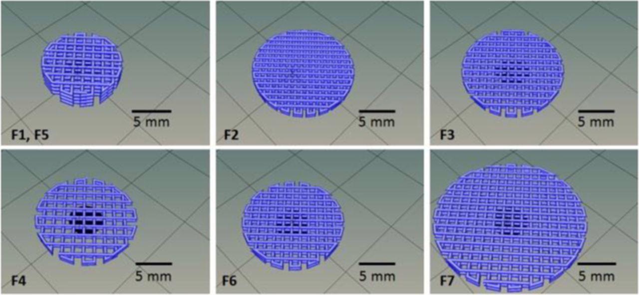
Figure 5. CAD models of the filters in Table I.
Figure 6a quantifies the MO photodegradation capability respectively of 15TiO2 and 30TiO2 filters, F1 and F5 in Table I, while their microstructure is reported in Figures 6c–6h. It is important to consider that both filters were printed following the same CAD model (F1 and F5 in Figure 5) having 8 layers and 10 mm of diameter. The preliminary photolysis and dark tests showed that neither photolysis nor adsorption processes occur. Plots in Figure 6a show that the designed porosity is higher enough to be infiltrated by the MO solution, and more than 50% MO degradation is recorded after 24 h with both compositions.
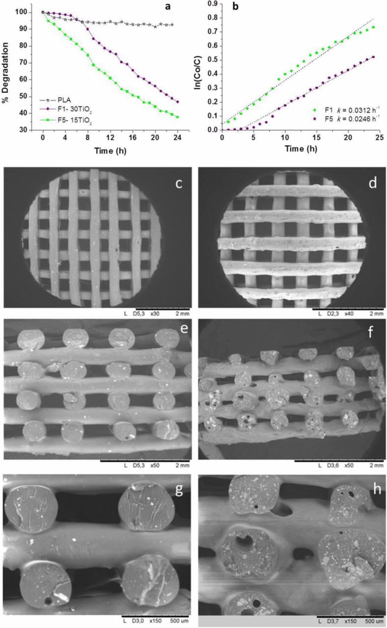
Figure 6. (a, b) Photodegradation of MO and kinetics of F1 and F5 filters; (c, e, g) FESEM images of the F1 filter; (d, f, h) FESEM images of the F5 filter at different magnifications.
According to a great number of researchers, the rates of photocatalytic oxidation of various dyes, MO included, over illuminated TiO2 fitted the Langmuir-Hinshelwood kinetics model:33
![Equation ([1])](https://content.cld.iop.org/journals/1945-7111/166/5/H3239/revision1/d0001.gif)
where r is the oxidation rate of the reactant, C is the concentration of the reactant, t the illumination time, k the reaction rate constant, and K is the adsorption coefficient of the reactant. When the initial chemical concentration of the dye (Co) is low, the above equation can be simplified to an apparent first-order equation:
![Equation ([2])](https://content.cld.iop.org/journals/1945-7111/166/5/H3239/revision1/d0002.gif)
The plots of ln (Co/C) versus time (t) represent a straight line with a slope k that is the apparent first-order rate reaction constant.34 These considerations are valid for TiO2 as powder samples or immobilized in a film or coating form. In this stage of the study, we assume to be in the same conditions to evaluate the MO degradation kinetic in presence of the hybrid filters. The obtained plots (Figure 6b) confirm that the MO degradation follows a first-order kinetic model, although it is important to note that the 30TiO2 filters achieve this degradation regimen after 5 h. Moreover, k values demonstrate that the F1 (15TiO2) filter exhibits better photocatalytic behavior in degrading MO. The differences in the reaction rates, or in the photocatalytic behavior, are usually associated with changes of the structure, texture and porosity of the microstructure.28
Comparing the two filters, the F5 (30TiO2) shows less effectiveness in degrading the MO solution. Figures 6c–6h show the SEM images of the top view and the cross section of both filters F1 (c, e and g) and F5 (d, f and h) at different magnifications. Figures 6c and 6d illustrate the 3D periodic structures composed, especially in the F1 case, by smooth surfaces and quite uniform cylindrical rods. However, observing the cross section of the scaffolds (Figures 6e–6h) the incorporation of a double amount of TiO2 NPs promotes a partial collapse of the porous structure. Although the bed and nozzle temperature are kept constant for both composites, a regular printing is impeded by the presence of a higher inorganic charge amount finely dispersed within the PLA matrix. Irregular printing leads to the deposition of asymmetrical rods reducing and sometimes closing the pre-designed porosity of the filter, and then, lowering the filter surface area exposed to the dye molecules.
F1 and F5 filters dimensions are far from that designed (see Figure 5 and Table I). The whole scaffold height decreases down to 2.75 mm, instead of the designed 3.20 mm, since the holes height decreases down to 0.32 mm (versus 0.4 mm at the CAD model) due to the deformation of the bars during the layer-by-layer printing, evidenced in Figure 6e. Similarly the bars also deform acquiring lengths up to 0.59 mm (versus 0.4 mm at the CAD model), while the holes length decreases, ranging 0.43–0.56 mm. Consequently the porosity decreases in F1 (15TiO2) filter if it is compared with the reference structure in Figure 5. This effect is more pronounced in the F5 filter (30TiO2 in Figure 6f). In fact the F5 scaffold height reduces to 2.00 mm. At higher magnifications, the reduction of the spaces between bars in different layers, as well as the decreasing (even inexistent) spaces between bars in the same layer, are evident. Comparing the structures in Figures 6g and 6h also demonstrates that an increase of the NPs amount leads more defects inside the rods core (closed porosity) while the increase on NPs doesn't take place necessarily in the bars surface, and can reduce the photocatalytic effectivity. In view of the FESEM results, degradation kinetics could be affected by the fact that the NPs imbibed in the composite are partially available at the surface of the filter rods, but also the structure collapse impedes the homogeneous irradiation of all the structure due to partial shading effects between each other bars.
Figures 7a and 7b quantified the MO photodegradation of 30TiO2 filters designed with 40% infill using nozzles of 0.4 mm of diameter, scaffold diameters of 10, 14 and 20 mm, and 8 or 4 layers, exhibiting weights ranging 0.12–0.18 g, corresponding to the filter F5, F6 and F7 in Table I, which SEM images are showed in Figures 7c–7h and insets, respectively.
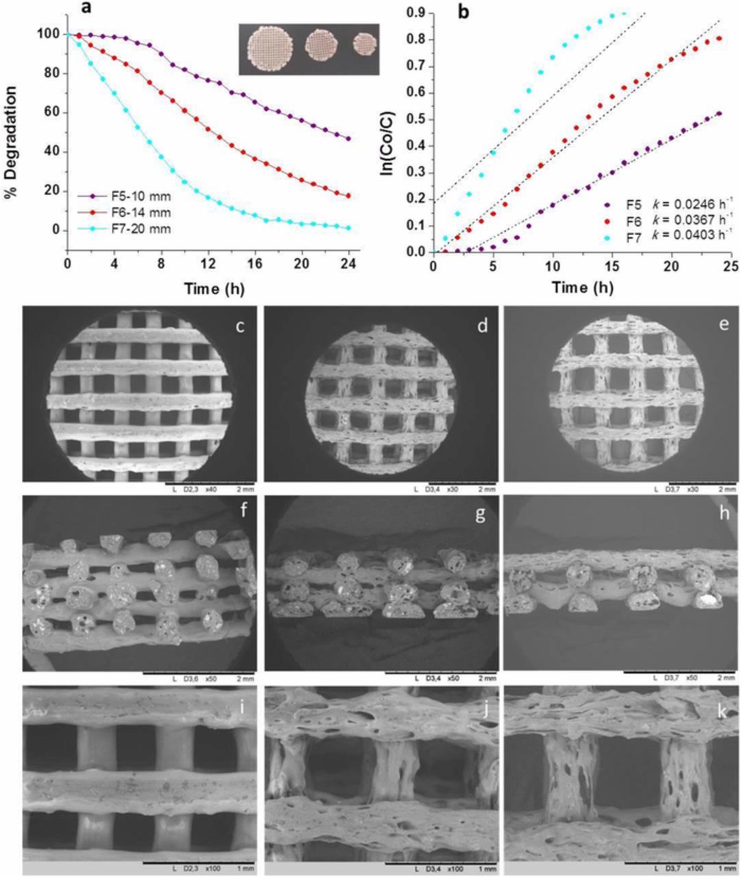
Figure 7. (a, b) Photodegradation of MO and kinetics of F5, F6 and F7 filters; (c, f, i) FESEM images of the F5 filter; (d, g, j) FESEM images of the F6 filter; (e, h, k) FESEM images of the F7 filter at different magnifications.
The F7 filter (20 mm in diameter and 4 layers) shows the highest efficiency in degrading the MO solution, after 20 hours, a total degradation of the dye molecules is achieved. This effect is ascribed to the potential higher exposed surface area and the higher amount of TiO2 NPs included in the three-dimensional structure. Although scaffold bars maintain their diameter, the holes length differs from the CAD model (Figure 5 and Table I) similarly to what occurs in the F5 filter, that corresponds to the same feedstock composition (30TiO2). However, the wall-roughness of the rods plays an important role on the filters behavior. Comparing the Figures 7i, 7j and 7k, extremely rough surfaces are illustrated going from the F5 (10 mm in diameter and 8 layers) to the F7 sample, probably indicating a scale-up effect during the FDM deposition of the largest one. However, this microstructure composed of superficial voids and irregular surfaces perfectly matches the requirements needed to have a higher surface area in contact with the dye solution, thus justifying the good photocatalytic performance of the F7 filter. The kinetics of MO photodegradation obtained using these filters (Figure 7b) confirm that the F7 filter is the most performing one, however, looking at the relative curves, only the F6 filter follows a first-order kinetic model as well as F5 filter after the first 5 h. F7 shows a different behavior that is ascribed to its unique microstructure, illustrated in Figures 7e, 7h and 7k.
Figures 8a and 8b report the MO photodegradation of 15TiO2 filters designed with a diameter of 14 mm and 4 layers varying the infill from 30% to 20% (nozzle diameter of 0.3 mm). They exhibit weights ranging 0.13–0.08 g, corresponding to the filter F2, F3 and F4 in Table I respectively, which pictures are showed in the inset. In terms of photocatalytic degradation of the MO solution, higher infill % values lead to the best performance, as in the F2 case (30%). The initial dye concentration is reduced of about 80% during the test. In this case, all the samples follow a first-order kinetic model with the F2 filter showing the highest k value, equal to 0.0338 h−1. Keeping constant the rods wall roughness (Figures 8c, 8e and 8g) this trend mainly relies on the major amount of TiO2 present on the F2 filter, because of the higher mass, and thus the higher presence of photocatalytic sites. Figures 8c–8h report the SEM images of the top view and the cross section of the filters F2 (c and d), F3 (e and f) and F4 (g and h) (in Table I). All the micrographs reported in Figures 8c–8h show 3D structures composed of well-aligned rods that maintain their initial shape even without support of the underlying layer.
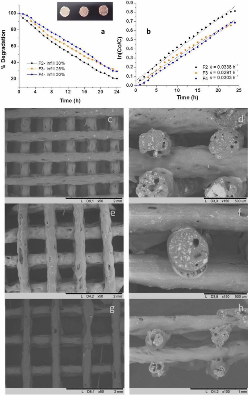
Figure 8. (a, b) Photodegradation of MO and kinetics of F2, F3 and F4 filters; (c, d) FESEM images of the F2 filter; (e, f) FESEM images of the F3 filter; (g, h) FESEM images of the F4 filter at different magnifications.
Finally, the stability of PLA/PEI-TiO2 composites was measured by thermogravimetric test after the photodegradation test. Figure 9 illustrates the TGA (Figure 9a) and their respective derivative thermograms (DTGA) curves (Figure 9b) of pure PLA and both, 15TiO2 (F3, Figure 8a) and 30TiO2 (F7, Figure 7a) filters, able to degrade the 70% and 100% of MO after 24 h, respectively. Weight losses of the polymer and composites take place between 250 and 450°C, with a maximum rate around 350°C, evidencing that the composites degrade similarly to PLA. That means that the PLA matrix of the composites at least maintains its thermal properties after a double thermal process (extrusion and printing). The inorganic residue of the filters decomposition at 450°C is 15 and 25% of 15TiO2 and 30TiO2 composites, respectively, evidencing a slight loose of TiO2 content of the 30TiO2 filters during their double thermal processing, i.e. at the extrusion of the composites filaments and the FDM printing of filters.
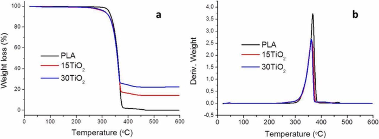
Figure 9. (a) Thermograms and (b) TGA derivate of F3 (15TiO2) and F7 (30TiO2) filters.
The results of a detailed study of the filters after operation, in particular the initial degradation temperature (T0), the maximum degradation temperature (Tmax) and the final degradation temperature (Te) data, are summarized in Table II. The maximum peaks in the DTGA curves represent the temperatures at maximum degradation rates (Tmax). Although the PLA is a biodegradable polymer its degradation properties are influenced by different factors such as polymer crystallinity, chemical bond, temperature or UV radiation.35 The results show that the composite thermal degradation happens at practically the same temperature as the pure PLA therefore no photodegradation of the polymer matrix is observed, induced by the TiO2 nanoparticles, since MO is more susceptible to oxidation. Moreover, contrary to what could be expected, the PLA matrix doesn't seem to be degraded after 24 h dipped in a MO aqueous solution. In this sense, the heat barrier role of TiO2 particles36 in these composites should be considered since the inorganic load addition could mask in the thermal tests a slightly PLA degradation by dissolution in the aqueous solvent during the photodegradation test. On the other hand, the improvement of mechanical properties could be expected due to the increase of the content on TiO2 in the feedstock.37 However a higher amount of inorganic particles in the polymeric matrix promotes printing irregularities such as the closed porosity and voids at the bars core as well as the formation of the wall-porosity. Although these last microstructural defects step up the photocatalytic activity of the filters they could compromise the mechanical properties improvement. Consequently, once the thermal degradation of the polymeric matrix has been avoided by substituting the thermal mixing of the PLA and TiO2 NPs by the proposed colloidal processing for the feedstock preparation, further research should be addressed to optimize the filters mechanical properties while maintaining their photocatalytic performance. In view of the obtained results, we can assume that it is possible to process scaffolds with an improved photocatalytic response retaining the composite structure at least during the photodegradation test, and hence keeping immobilized the photocatalyst.
Table II. Thermal degradation temperatures: initial degradation (T0), maximum degradation (Tmax) and the end of degradation (Te) temperatures.
| T0 (°C) | Tmax (°C) | Te (°C) | |
|---|---|---|---|
| PLA | 338 | 368 | 376 |
| 15TiO2 | 336 | 361 | 371 |
| 30TiO2 | 336 | 362 | 368 |
Conclusions
Eco-friendly and biopolymer-based composites, able to photodegrade an organic molecule, were designed for 3D printing of photocatalytic filters. 3D scaffolds with an engineered microstructure and containing immobilized TiO2 NPs in PLA, were for the first time printed by fused filament fabrication or fused deposition modeling (FDM) with low-cost 3D printers. FDM allows the manufacture of customized 3D pieces, and in this work, the variation of the 3D scaffold geometry, by manipulating the printer parameters, leads to achieve the 100% degradation of MO for 70:30 (wt/wt) PLA:PEI-TiO2 composites.
New polymer composites were produced by incorporating modified PEI-TiO2 NPs in a thermoplastic biopolymer such as PLA. PEI adsorption onto the nanopowders surface provides the needed stability to disperse NPs during the whole process, from the mixture of the PLA and TiO2 NPs in a THF suspension to the final homogenous distribution of TiO2 in the PLA matrix at the FDM scaffolds. Moreover, the surface modification of the TiO2 NPs allows increasing the inorganic loading of the polymer minimizing charge losses during the manufacturing of filaments and scaffolds by the extrusion and printing for the composites formulated with the highest TiO2 contents (70:30 (wt/wt) PLA:PEI-TiO2). The increase of the inorganic charge in the polymer as well as the scaling up parameters used produce to a valuable wall roughness/porosity in the scaffolds rods that propitiates the photocatalysis.
Acknowledgments
Authors acknowledge the support to the projects S2018/NMT-4411 (Comunidad de Madrid) and MAT2015-70780-C4-1 (MINECO/FEDER). Z. Gonzalez acknowledges the Spanish Ministry of Economy and Competitiveness for the Postdoctoral Fellowship: IJCI-2016-28538. J. Yus acknowledges to the Comunidad de Madrid the support from the Youth Employment Initiative, CAMPD17_ICV_002. The authors thank ECERS for funding on Mobility Project JECS Trust Contract number: 2017294.
ORCID
B. Ferrari 0000-0003-3377-6844