
Abstract
The Rotating Disk Slurry Electrodeposition (RoDSE) technique is a novel method allowing to deposit electrochemically metal nanoparticles on a given conductive support and produce a powder catalyst for diverse applications, for example, ethanol oxidation reaction (EOR). This technique was used to electrodeposit Pd nanoparticles on carbon Vulcan XC–72R nanoflakes at three different applied potentials (0.0, 0.4, and 0.7 V vs. RHE). The potentials were chosen based on different regions of Pd electrodeposition on a clean glassy carbon electrode. Each Pd/Vulcan catalyst was characterized through different spectroscopic, microscopic, and electrochemical techniques. Powder X-ray diffraction and transmission electron microscopy studies verified the Pd crystallinity and particle size, respectively. The Pd particle size decreased with a more positive applied electrodeposition potential at carbon Vulcan XC–72R nanoflakes. X-ray photoelectron spectroscopy determined that the applied potential affected, both, the final palladium and carbon oxidation states. Finally, cyclic voltammetry was used to characterize the electrocatalytic activity of each Pd / Vulcan catalyst in 0.1M KOH and for the EOR. It was found that, for Pd electrodeposition, an applied potential of 0.4 V vs. RHE provided harmony between a mass transport and kinetically controlled deposition thereby providing the optimal conditions to produce a better catalyst with better EOR.
Export citation and abstract BibTeX RIS
One of the oldest energy conversion devices are fuel cells.1 They are electrochemical devices that convert chemical energy of a given fuel into electrical energy. Alkaline fuel cells (AFCs), which use hydrogen as fuel and KOH as supporting electrolyte, hold several advantages over other type of fuel cells such as easy handling and relatively low operating temperatures (around 20–70°C). Additionally, the kinetics of the oxygen reduction reaction (ORR) are faster in alkaline media than in acidic conditions, allowing the usage of non–precious metal catalysts, making the fuel cell economically viable.1,2
However, the main challenge for the commercialization of alkaline fuel cells is the availability of economically viable hydrogen storage technology and the lack of hydrogen transportation and distribution infrastructures. Liquid fuels, such as ethanol and methanol, provide an attractive alternative as fuels in AFCs, because of their easy storage and high energy densities.3 The main disadvantage of using methanol as fuel is its very high toxicity; and excessive inhalation can cause blindness or have an effect on the optical nerve.4–6 On the other hand, ethanol is a bio–fuel, which is less toxic than methanol and can be easily obtained from a variety of feedstock such as corn, sugarcane, wheat or even cellulose. Additionally, much like the ORR, electrochemical oxidation of ethanol is more facile in alkaline media and infrastructures for storage and transportation for ethanol already exist.4
A variety of techniques have been employed for the deposition of metal nanoparticles onto different support materials (e.g. chemical and thermal deposition, laser deposition, microwave–assisted, sol–gel among others).7–9 Moreover, electrodeposition techniques have been used as well.10,11 The rotating disk slurry electrodeposition technique (RoDSE), developed in our laboratory, has been proven to deposit metal nanoparticles on different support materials for bulk production of catalyst powder.12–18 This technique works by maintaining a circular flux of solution by rotation of the working electrode, constantly replenishing the concentration of the support material and metal ion in the diffusion layer (Figure 1), allowing the electrodeposition of the metal to take place in the conductive support. To the best of our knowledge, the RoDSE is the only electrochemical synthesis technique where you are able to produce a hybrid material in powder form. Furthermore, no dangerous chemicals, nor strenuous process, are required to complete this electrochemical synthesis. Thus, making RoDSE a valuable technique to produce catalysts for diverse applications.

Figure 1. General scheme of the electrochemical deposition of metal nanoparticles onto a carbon support via the RoDSE method.
In this work, Pd nanoparticles were successfully electrodeposited on Vulcan XC–72R nanoflakes via the RoDSE technique, at different applied potentials, and tested for the ethanol oxidation reaction in alkaline media. The effect of the applied electrodeposition potential on morphology, metal loading, size, and catalytic activity was studied
Experimental Method
Catalyst preparation
Pd was electrodeposited on Vulcan XC–72R nanoflake carbon support via the RoDSE technique adapting the same conditions previously reported by Santiago et al.12,13 A suspension was prepared in a beaker containing 50 mg of Vulcan XC–72R nanoflakes (from CABOT) and 20 mL of 0.1 M H2SO4 (Optima, Aldrich). It was sonicated for 8 h in order to create a highly dispersed slurry. The resulting suspension was placed in the center of a three–electrode cell assembly for the Pd electrodeposition as seen in Figure 2, containing three compartments separated by fritted glass. Afterwards, 2.00 mL of a 5.0 mM PdCl2 solution was added to the slurry, in the center glass container. The electrochemical cell was sealed and purged with ultrapure nitrogen for 15 min while the rotating disk electrode (RDE) (PINE Research Instrumentation) rotated at 1200 rpm in the slurry. The rotating disk working electrode was a glassy carbon electrode (GCE) with a geometric area of 0.20 cm2. The GCE was previously polished with 1.0, 0.3, and 0.05 μm Al2O3 paste (Buehler Micropolish) until reaching mirror like state. The residual polishing material was removed from the surface of the GCE by sonication in deionized water bath for 5 min. A high surface area Pt wire and RHE were used as a counter and reference electrodes, respectively.
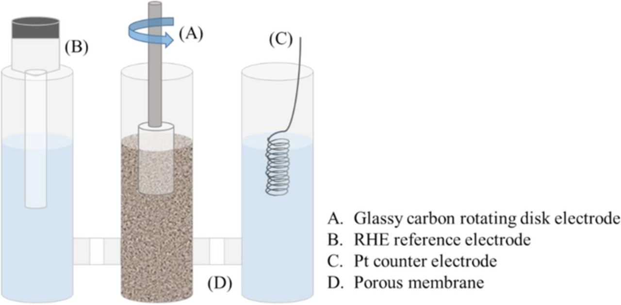
Figure 2. RoDSE electrochemical cell setup showing the placement of the working electrode, reference electrode, counter electrode and the porous membrane separating each compartment.
The Pd electrodeposition was done by applying a constant reductive potential for 2 h and after 2.00 mL, of a solution containing 5.0 mM PdCl2 precursor in 0.1M H2SO4, was added. This process was repeated 3 additional times. Finally, after the RoDSE process, the slurry was filtered with a 0.22 μm Nylon filter and washed with abundant deionized water. The resulting catalyst material was dried in a 60°C oven for 24 h and ground to obtain a fine powder.
Electrochemical measurements
Characterization of catalytic activity of produced powders was done using Pd catalysts paste modified GCE. 3 mg of catalyst powder were mixed with 150 μL of deionized water, 150 μL of isopropanol (Sigma Aldrich), 300 μL of ethanol (99.5% Sigma Aldrich) and 5 μL of Nafion solution (5% solution in alcohol, Sigma Aldrich). The mixture was sonicated for 1 h to form the paste. Glassy carbon electrodes, (3 mm diameter, from BASi) were polished three times with 1.0, 0.3 and 0.05 μm alumina powder, rinsed and sonicated for 10 minutes in deionized water to remove alumina residue. Afterwards, the GCE were subjected to 5 cycles of a cyclic voltammetry in 0.1 M KOH solution using a potential window of −0.1 to 1.1 V vs. Ag/AgCl, at a potential scan rate of 100 mV/s, to ensure that the resistance and capacitance were in optimal working conditions. Finally, 5 μL of the prepared catalyst paste was dropped on the clean GCE surface and was allowed to dry at 60°C for 120 s to obtain the modified GCE.
Characterization of the catalytic activity for each Pd/Vulcan catalyst was done under ambient conditions using cyclic voltammetry (CV) in alkaline media. All measurements were done using a PARSTAT 2273 potentiostat. In all experiments, a three electrodes cell was employed consisting of a Pt wire, reversible hydrogen electrode (RHE) and modified GCE as the auxiliary, reference and working electrodes, respectively.
For all Pd-based catalysts, the electrochemical active surface area (EASA) was calculated to evaluate the current density and thus the catalytic activity of each modified electrode. A charge value of 420 μC cm−2 is attributed for the reduction of the PdO monolayer during the cathodic sweep,19 as seen in Equation 1.20 All current densities reported in this work correspond to the EASA of Pd for each catalyst using this method of surface area calculation.
![Equation ([1])](https://content.cld.iop.org/journals/1945-7111/164/14/D1015/revision1/d0001.gif)
XRD measurements
The RoDSE synthesized Pd catalysts X-ray diffraction (XRD) patterns were obtained using a Rigaku SmartLab X-ray diffractometer working with a Cu Kα radiation (λ = 1.54 Å) source. The 2Θ range was scanned between 10–80° at a rate of 0.02° s−1.
TEM measurements
Transmission electron microscopy images were taken using the JEOL 1400 LaB6 Soft Bio TEM. A suspension was done by dispersing 5 mg of the catalyst powder in 7.00 mL of pure ethanol by ultra–sonication. A drop of the catalyst suspension was added to a 200 mesh Lacey Carbon copper grid. Particle size histogram was determined using Gatan Digital Micrograph software utilizing different regions of the carbon copper grid to obtain a representative view of each catalysts average particle size
Induced Coupled Plasma–Optical Emmission Spectrometry (ICP–OES)
Palladium metal catalyst loading were measured using an Optima 8000 Perkin Elmer ICP–OES. Briefly, 10 mg of each Pd / Vulcan catalyst was digested with 10 mL of aqua–regia solution and heated to simmering until 1 mL of solution remained. The solutions were passed through a Whatman glass microfiber filter (GF / F grade) and reconstituted with deionized water in a quantitative volumetric flask. Quantification was done in triplicates with an external calibration curve.
TGA measurements
Thermal stability of catalysts was evaluated by thermalgravimetric analysis (TGA) using the PerkinElmer STA 6000 thermal analyzer in air with a temperature ramp of 100°C min−1 and maintained at 900°C for 10 min.
XPS measurements
The effect of the applied potential on the chemical composition of catalysts surface was studied by X-ray photoelectron spectroscopy (XPS). High binding energy resolution (HR-XPS) spectra C 1s, O 1s and Pd 3d were analyzed using a fitting program (Multipack, Physical Electronics) for peak deconvolution. X-ray photoelectron spectroscopy (XPS) spectra were obtained using a PHI 5600ci spectrometer equipped with an aluminum polychromatic source (350 W) at a 45° angle and a hemispherical electron energy analyzer. The pass energy was 58.70 eV. A small sample of the catalytic powder was pressed onto copper tapes.
Results and Discussion
Pd electrodeposition
Cyclic voltammetry was done utilizing a clean GCE in a 5 mM PdCl2/0.1 M H2SO4 solution (Figure 3). A starting potential of 1.6 V was chosen to make sure that the Pd2+ ions were in solution. In the first potential scan, a cathodic peak near 0.53 V was observed, corresponding to the deposition of Pd onto the GCE. For each cycle, a characteristic Pd voltammogram is appreciated with higher currents for each cycle due to the deposition of more Pd as the cycles advance. Cathodic and anodic peaks between 0.05 and 0.2 V correspond to the adsorption/absorption and desorption of atomic hydrogen, respectively. According to the data presented in Figure 3, electrodeposition of Pd starts at potentials more negative than 0.7 V (near 0.65 V vs.). Because of this, three different applied electrodeposition potentials (0.0, 0.4 and 0.7 V vs. RHE) were chosen for the electrodeposition of Pd on the carbon support by the RoDSE method. However, the electrodeposition in a slurry solution may differ from the electrodeposition in solution, particularly the presence of carbon flakes can result in the depolarization of Pd deposition.
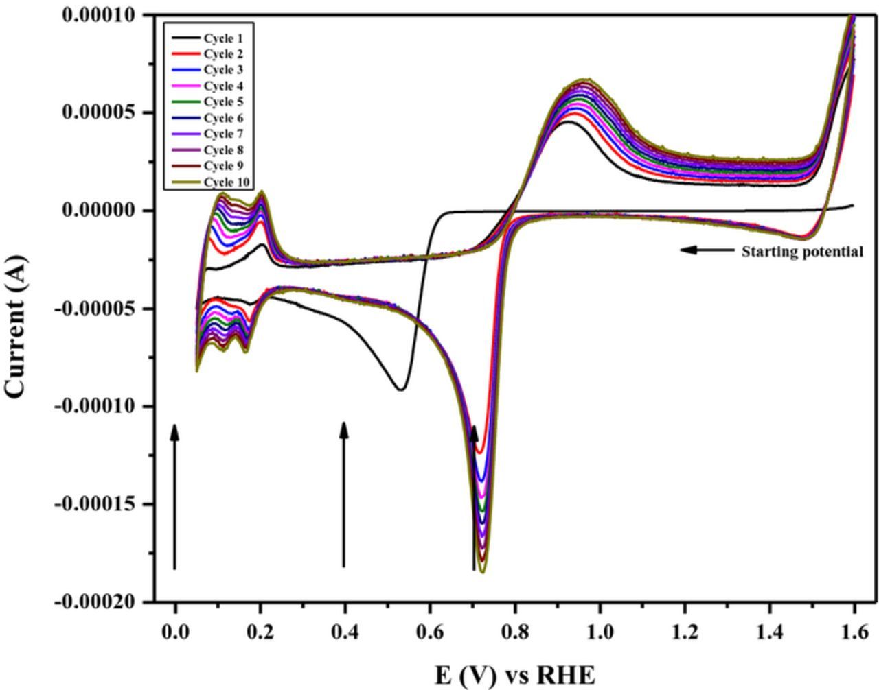
Figure 3. Cyclic voltammograms of a clean glassy carbon electrode in a 5 mM PdCl2/0.1 M H2SO4 solution at 25 mV/s. Arrows indicate the three different applied potential used for the Pd electrodeposition using the RoDSE method.
Figure 4 demonstrates the cathodic currents obtained for each added aliquot of the precursor solution in deposition of Pd on Vulcan XC-72R nanoflakes by the RoDSE technique. As expected the average deposition current decreases with the shift of potential to more positive values. At applied deposition potentials of 0.0, 0.4, and 0.7V vs RHE the average maximum deposition current was −1.3, −0.9, and −0.3 mA, respectively. The increase of currents observed in some cases in the beginning of the deposition cycles (near 700 s) is likely associated with the increase of the real electrode area as a consequence of Pd deposition. The further decrease with deposition time can be explained by depletion of Pd ions. Replenishment by adding the aliquots led to considerable increase of the currents.
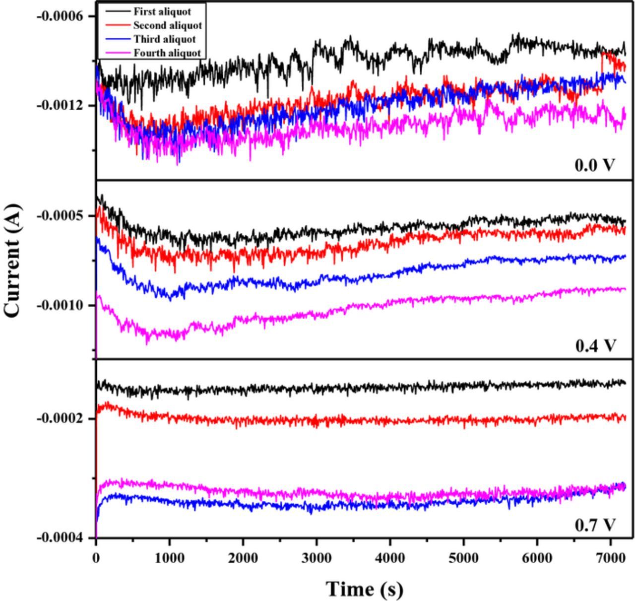
Figure 4. Current vs. time graphs for the Pd electrodeposition in 20 mL of a Vulcan XC–72R nanoflake slurry in 0.1 M H2SO4 at different applied potentials; 0.0, 0.4 and 0.7V vs. RHE. For each applied potential, four consecutive electrodepositions were done. In each electrodeposition, a 2 mL aliquot 5 mM PdCl2/0.1 M H2SO4 solution was added to the slurry.
X-ray diffraction (XRD) measurements
X-ray diffraction (XRD) analysis was done for each of the synthesized Pd/Vulcan nanoflakes catalyst to verify the palladium patterns. XRD patterns of all samples (Figure 5) show three peaks at 2Θ = 40.0°, 46.5°and 68.1° corresponding to the (111), (200) and (220) planes of the Pd face center cubic structure, respectively.21 A broad peak appears at 25.0° corresponding to the (200) plane of Vulcan XC–72R nanoflakes. Thus, the results of XRD confirm the successful deposition of crystalline palladium on the carbon support.
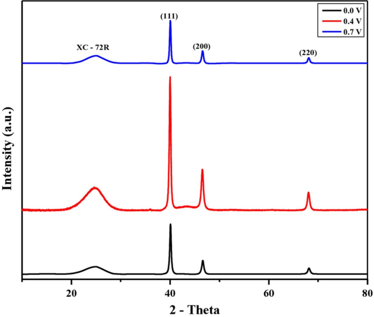
Figure 5. XRD pattern for the Pd/Vulcan XC–72R nanoflake catalyst synthesized by RoDSE at 0.0 V (black), 0.4 V (red) and 0.7 V (blue) vs. RHE applied potentials.
Transmission electron microscopy (TEM) measurements
Transmission electron microscopy (TEM) was used to determine particle size and dispersion for each Pd electrodeposition. Microphotographs of Pd/Vulcan XC–72R nanoflakes catalysts (Fig. 6) shows strong tendency to agglomeration of Pd particles deposited at 0.0 V vs. RHE, resulting in Pd islands with occasional, relatively small, Pd nanoparticles. However, as the electrodeposition potential becomes more positive (0.4 V vs. RHE), it becomes apparent that the Pd islands are less frequent and smaller. At this same potential, smaller Pd nanoparticles can be found frequently and homogenously dispersed on the carbon support. Finally, at the other boundary of the applied potential (0.7 V vs. RHE), we can see that there is no apparent Pd island formation and there are small and well-dispersed palladium nanoparticles. These results concur with the results obtained in the electrodeposition process. At stronger electrodeposition potential (0.0 V vs. RHE), a higher deposition current was obtained indicating that palladium was being deposited in a more aggressive way thus making agglomeration favorable. However, as the electrodeposition potential was weaker, less electrodeposition current was obtained stipulating a milder deposition of palladium on the carbon support, consequently, less agglomeration occurs. However, this also leads us to suspect less palladium deposited by mass as the applied potential is milder.
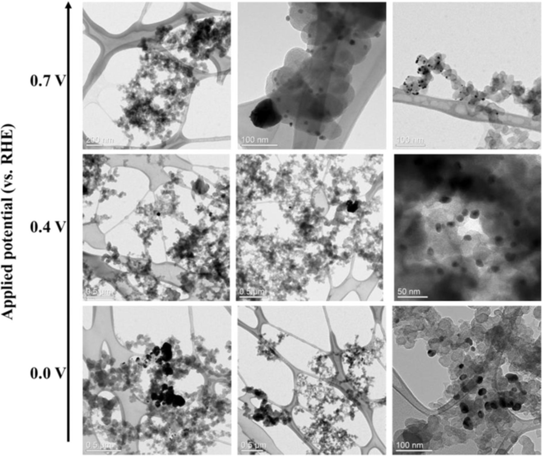
Figure 6. Transmission electron microscopy images, at different magnifications, of the Pd/Vulcan XC–72R nanoflake catalysts synthesized by RoDSE at 0.0 V (bottom, scale bar: 0.5μm; 0.5μm; 100nm from left to right), 0.4 V (middle, scale bar: 0.5μm; 0.5μm; 50nm from left to right) and 0.7 V (top, scale bar: 200nm; 100nm; 100nm from left to right) vs. RHE applied potentials.
Even though a small amount of subjects were obtained, a particle size histogram was done for each synthesized Pd/Vulcan catalyst (Figure 7). The particle size histograms for the Pd/Vulcan XC- 72R nanoflakes catalysts synthesized at different potentials show clearly the increase of particle agglomeration with the shift of potential to more negative values. The average size of Pd agglomerates for deposition at 0.7 V, 0.4 V and 0.0 V less than 10 nm, near 15 nm and more than 30 nm, respectively. The increase of Pd deposition intensity with the shift of potential to more negative potentials can explain the increase of Pd particles agglomeration level.
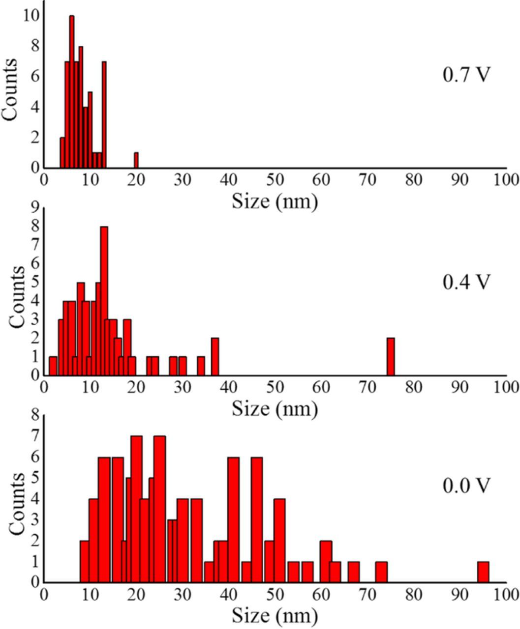
Figure 7. Particle size histogram from TEM images of each Pd/Vulcan XC 72R nanoflakes catalyst synthesized at 0.0 V (bottom), 0.4 V (middle) and 0.7 V (top) vs. RHE with a total particle count of 92, 60 and 53, respectively.
Inductively couple plasma–optical emission spectroscopy (ICP–OES)
The analytical percentage of the total Pd loading in each catalyst sample are shown in Table I. It is clear that the Pd/Vulcan nanoflakes catalyst synthesized at 0.0 V contains the most Pd by mass followed by 0.4 and 0.7 V, respectively. These results agree with the TEM images, as it was more challenging to find Pd metal deposited on the carbon support for more positive applied potentials. These results validate our initial hypothesis that at milder potential less amount of palladium, by mass, is deposited on the carbon support.
Table I. Metal % m/m for each Pd/Vulcan catalyst synthesized at different applied potentials.
| Applied potential (V vs RHE) | Metal percentage (% m/m) |
|---|---|
| 0.0 | 6.43% |
| 0.4 | 5.04% |
| 0.7 | 3.81% |
Thermal gravimetric analysis (TGA)
The results of TGA are presented in Figure 8. Thermal decomposition of all the synthesized Pd/Vulcan nanoflake catalysts can bee seen in Figure 8 (top). It is clear that at low temperatures all catalysts have the same thermal behavior, however as the temperature increases the weight percentage, of the catalyst synthesized at 0.7 V vs RHE, decays more rapidly than its two counterparts, suggesting that the catalyst synthesized at 0.7 V is less thermally stable than the catalysts synthesized at 0.0 V and 0.4 V vs RHE. After reaching 900°C (bottom), the Pd loading were 6.87%, 6.54% and 4.43% for the catalyst synthesized at 0.0, 0.4 and 0.7 V, respectively. These results follow the same trend as the ICP–OES results although with higher mass loading, found by TGA, may be due to the formation of a PdO layer at high temperature.22 The faster decrease in mass for the Pd/Vulcan catalyst synthesized at 0.7 V vs. RHE may be due to the considerable decrease of deposited palladium by mass and larger amounts of carbon functionalities, as observed by XPS. As less palladium is deposited, more of the Vulcan XC–72R nanoflake surfaces are in contact with supporting electrolyte solution. As the applied potential is slightly oxidative for the carbon support, more oxygen defects are formed on the surface of the carbon support. This would allow for easier combustion and, consequently, a faster decrease in mass for the catalyst synthesized at 0.7 V vs. RHE. However, 0.4 V vs. RHE is not sufficiently positive to oxidize Vulcan XC–72R as much as 0.7 V vs. RHE, whereas less oxygen defect are formed and higher thermal stability is observed.
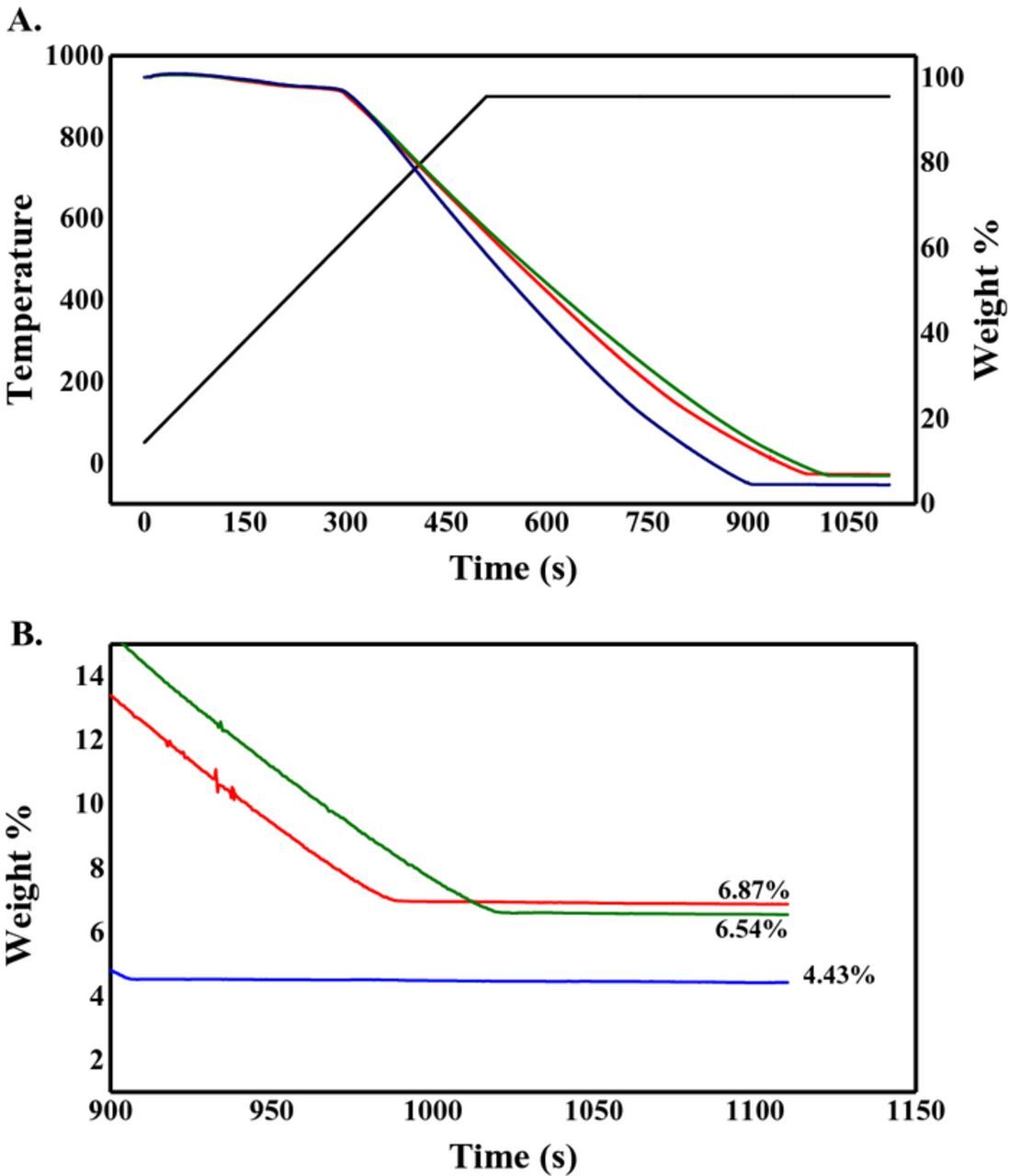
Figure 8. Thermal gravimetric analysis, in air, with a temperature ramp of 100°C min−1 and maintained at 900°C for 10 min, for the Pd/Vulcan XC–72R nanoflake catalyst synthesized by RoDSE at 0.0 V (red), 0.4 V (green) and 0.7 V (blue) vs. RHE applied potentials. (B) Weight percentage obtained for each synthesized Pd/Vulcan XC–72R nanoflake catalyst after the conclusion of the analysis.
X-ray photoelectron spectroscopy (XPS)
High resolution X-ray photoelectron spectroscopy (HR-XPS) spectra for C 1s, O 1s and Pd 3d binding energy region of the catalysts fabricated at different potentials are shown in Figure 9. The XPS results for Pd 3d, O 1s and C 1s binding energy regions were analyzed using curve–fitting program (Multipack) for peak deconvolution. The peak assignments for the C 1s components are shown in Table II.23 The O 1s binding energy peak assignments were ∼530.3 eV, ∼552 eV and ∼533 eV, attributed to PdO,24 C-O25 and C=O,25 respectively.
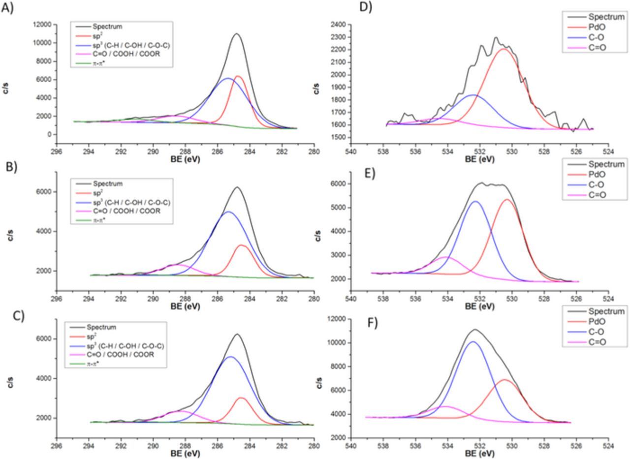
Figure 9. (A–C) C 1s and (D–F) O 1s XPS spectra of the Pd/Vulcan XC–72R nanoflake catalyst synthesized by RoDSE at (A and D) 0.0 V, (B and E) 0.4 V and (C and F) 0.7 V vs. RHE applied potentials.
Table II. X-ray photoelectron spectroscopy C 1s binding energy peak assignments.
| Carbon 1s Components | Binding Energy (eV) |
|---|---|
| Graphite (sp2) | 284.4 |
| C-H (sp3) | 285.0 |
| C-OH/C-O-C (sp3) | 286.1–286.3 |
| C=O | 287.6–287.7 |
| COOH/COOR | 288.6–289.1 |
| π-π* | 290.5–290.8 |
The Pd 3p binding energy peaks usually overlaps with the O 1s peak.24 However, all catalyst samples showed a minimal Pd signal, within the noise level. The highest was for the catalyst prepared with a 0.0V applied potential, which showed 0.5% in Pd when compared with O and C. Therefore, the 3p binding energy peak should be in the noise level, as well. The abundance of carbon Vulcan nanoflakes may block the 3p and 3d Pd electrons. Since the presence of Pd was observed by XRD and ICP–OES, the O 1s binding energy peak was fitted assuming contribution from the oxygen of PdO functionalities. The C 1s peak contains various features that could not be fully resolved. Instead of fitting all 6 components, the peak deconvolution was carried out as described in Table III and the contribution for each component of the C 1s and O 1s are described in Table IV.
Table III. C 1s components for X-ray photoelectron spectroscopy binding energy peak deconvolution.
| Carbon 1s Components | Binding Energy (eV) |
|---|---|
| sp2 | ∼284.7 |
| sp3/ C-OH/ C-O-C | ∼285.4 |
| C=O/COOH/COOR | ∼288.7 |
| π-π* | ∼291.0 |
Table IV. Contribution for the C 1s and O 1s binding energy components of the X-ray photoelectron spectroscopy measurements shown in Figure 9 for each Pd/Vulcan XC–72R nanoflake catalyst synthesized by RoDSE at 0.0 V, 0.4 V and 0.7 V vs. RHE applied potentials.
| Carbon 1s Component % Contribution | Oxygen 1s Component % Contribution | ||||||
|---|---|---|---|---|---|---|---|
| Sample | sp2 | sp3/ C-OH/ C-O-C | C=O/COOH/COOR | π-π* | PdO | C-O | C=O |
| 0.0 V | 45.3% | 43.4% | 8.3% | 3.0% | 67.9% | 26.6% | 5.5% |
| 0.4 V | 23.5% | 66.6% | 9.2% | 0.7% | 46.6% | 43.6% | 9.8% |
| 0.7 V | 17.7% | 77.6% | 4.7% | 0.0% | 32.0% | 59.2% | 8.8% |
The O 1s XPS binding energy peak showed that the applied electrodeposition potential greatly affected the amount of oxygen containing species on the synthesized catalysts. It can be observed from the spectra, that for the 0.0 V vs. RHE electrodeposition sample there was very little oxygen contribution when compared with the other two catalysts samples. The majority of the oxygen XPS binding energy signal, for the 0.0 V vs. RHE electrodeposition catalyst sample, came from PdO. In general, the amount of oxygen functionalities increased concomitant with more positive electrodeposition potential. Congruently, The relative amount of PdO decreased with a more positive electrodeposition potential. It may be concluded that with a more positive applied electrodeposition potential, more oxidized carbon species are available in the Vulcan XC-72R nanoflake matrix.
The data of Table IV indicate the following effects of the potential applied during Pd electrodeposition. As follows from analysis of HR-XPS C 1s peak, the shift of potential to more positive values leads to the decrease of PdO concentration (that can be explained by the less intensive Pd deposition) and to the increase of concentration of oxidized carbon species with C-O and C=O functionalities on the surface of the catalysts. These findings are consistent with those from analysis of HR-XPS O 1s peak. The concentration of components attributed to sp2, π-π* and sp3 (COO) decrease with the shift of potential to more positive values while the concentration of component associated with C-O strongly increases. The relatively high concentration of oxygen containing species at 0.7 V is presumably contributed to the lower catalysts thermal stability.
Electrochemical measurement
The electrocatalytic activity, towards ethanol oxidation reaction (EOR) in alkaline media, for each Pd/Vulcan nanoflakes catalyst was tested by cyclic voltammetry. Figure 10A shows cyclic voltammograms in 0.1 M KOH of modified glassy carbon electrodes with all the synthesized Pd/Vulcan nanoflakes catalysts. Cathodic peaks observed at 0.65 V vs. RHE are due to the reduction of the PdO monolayer formed in the anodic sweep.20 However, the foremost difference with each CV consists in the difference of the capacitance double layer current which is directly related to the applied electrodeposition potential used to deposit Pd on Vulcan XC–72R nanoflakes support. This observation can be explained by the less amount of deposited Pd, at more positive electrodeposition potentials, and consequently by the larger carbon area free of Pd in contact with the electrolytic solution. In addition to the amount of Pd, it has been shown that the capacitance current also increases due to surface oxidation defects on the carbon surface.26,27 Thus, the changes of capacitance with potential are consistent with the XPS results reported above.
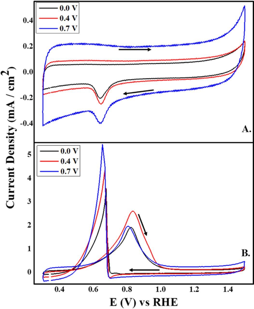
Figure 10. Cyclic voltammograms in (A) 0.1 M KOH and (B) 0.5 M EtOH/0.1 M KOH for the Pd/Vulcan XC–72R nanoflake catalyst synthesized by RoDSE at 0.0 V, 0.4 V and 0.7 V vs. RHE applied electrodepostion potentials. The scan rate was 25 mV/s. Arrows indicate the potential sweep direction.
The catalytic activity for each Pd/Vulcan nanoflake catalyst was examined by cyclic voltammetry for EOR in alkaline media (Figure 10B). There are two peaks corresponding to ethanol oxidation. In the anodic sweep, an ethanol oxidation peak appears between 0.81 to 0.84 V vs. RHE, for the three catalysts. These peaks are attributed to the ethanol electrooxidation by adsorbed oxygen containing species of Pd (Pd–OHads) which form in alkaline media.20 However, beyond 0.84 V vs. RHE the current density decreases as the potential is increased until the current concurs with the base current. This is due to Pd (II) oxide layer formation on the surface of the nanoparticles, which blocks the active Pd species leading to a decrease in the electrocatalytic activity. In the cathodic potential sweep, lower than 0.65V vs. RHE, the ethanol oxidation reaction reoccurs due to the reduction of the Pd (II) oxide layer recovering the electrocatalytic activity of the catalysts. Figure 10B, demonstrates close catalytic activities for all Pd/Vulcan XC–72R nanoflakes catalysts for EOR with the catalyst synthesized at 0.4V vs. RHE having a slightly higher peak current density. In the cathodic sweep, this catalyst maintained an ethanol oxidation current density at more negative potentials than the other two catalysts.
It is notable that, even with less Pd loading, the Pd catalyst synthesized at 0.7 V vs. RHE had a slightly higher current density than the Pd catalyst synthesized at 0.0 V vs. RHE. These variations in current density can be explained by the difference in amount and aggregation level of Pd nanoparticles deposited on Vulcan XC–72R nanoflakes support at the different applied electrodepositon potentials.
Conclusions
In this work, the effect of the applied potential used in the Pd electrodepositon on Vulcan XC-72R nanoflakes by RoDSE method was studied. It was found that, independently of the applied potential, polycrystalline Pd nanoparticles deposits on the Vulcan nanoflake support. However, results from TEM, ICP–OES and TGA demonstrates that, as the applied potential is more positive, the Pd nanoparticles are of a smaller size but less Pd by mass is deposited on the carbon support. This is due because as the applied potential is more positive, XPS results demonstrate that there are more oxygen species on the carbon support, making home for more nucleation sites for smaller and less agglomerated Pd nanoparticles. However, these oxygen defects on Vulcan XC–72R also lead to faster thermal decomposition as seen in the TGA results.
Even though the deposition of Pd at 0.7 V vs. RHE demonstrated smaller nanoparticles, the synthesis done at 0.4 V vs. RHE demonstrated a slightly higher electrocatalytic activity towards ethanol oxidation. These suggests that applying an electrodeposition potential of 0.4 V vs. RHE, in the RoDSE electrodeposition process, provided the optimal conditions to produce a Pd nanocatalyst with high electrodeposition yield (83.3%), low agglomeration, thermally stable, and relatively small nanoparticles, which leads to better EOR.
Acknowledgments
This work was financially supported by the NSF-CREST Center for Innovation, Research and Education in Environmental Nanotechnology Grant Number HRD-1736093 and NASA-EPSCoR grant number NNX14AN18A. This research used resources of the Center for Functional Nanomaterials (CFN), which is a U.S. DOE Office of Science Facility, at Brookhaven National Laboratory (BNL) under Contract No. DE-SC0012704. CAV thanks Kim Kisslinger (CFN-BNL) for assistance on the TEM images.