
Abstract
Various kinds of activated carbon/activated carbon fibers were used in the evaluation of electrical double layer capacitors using the method of image analysis. The appropriate hydrated ion structures in an aqueous system of  and an organic system of
  carbonate were calculated using the software Cerius2 (ver. 3.8). The capacitance obtained varied with the electrolyte used, even though the capacitor material remained the same. The relationship between the pore size and the electrolyte ion diameter is discussed. © 2001 The Electrochemical Society. All rights reserved.
Export citation and abstract BibTeX RIS
An electrochemical double-layer capacitor (EDLC) is defined as a device using electric current between an electronic conductor and an ionic conductor. The classic double layer is established when an electronic conductor is in contact with an ionic conductor; a charge separation takes place on either side of the interface, leading to the development of a double layer.
Today's commercial electrochemical double-layer capacitor (EDLC) is a small, battery-like device that can provide power during the temporary failure of primary power sources.1 2 3 4 The most common application for these small double-layer capacitors is as a semiconductor memory backup power source for any device which contains complementary metal oxide semiconductor (CMOS), random access memory (RAM), or microprocessor storage. They are also used as auxiliary power sources for mechanical operations in small appliances like laptop computers, alarms, VCRs, telephones, and camcorders. Double-layer capacitors are well suited as a backup source because of their high energy storage density, low cost, and maintenance-free operation. In addition, studies of high energy density capacitors for use in electric vehicle drivelines have been performed.5 6
EDLCs with a packaged energy density as high as 3 to 5 Wh/kg were manufactured using activated carbon electrodes.7 8 This energy density depends on the basic electrochemical properties of the carbons and on the specific manufacturing technology that is employed. The capacitive storage comes from the electrochemical double layer formed at the electrode/electrolyte interface. Thus the specific capacitance of an EDLC electrode is linked to the physical area, to the pore size, to the ionic accessibility of the electrode material, and to the electrolyte properties.
In particular, the pore size distribution (PSD) has been considered to be the most important parameter, because the accessibility of ion molecules in an electrolyte strongly depends on the pore size of the electrodes. Image analysis of transmission electron microscopy (TEM) images has developed into a powerful method for analyzing the PSD of the electrode material.9 10 Hence, we took a new approach, using image analysis of TEM images, to improve our understanding of the relation between the pore size distribution (PSD) of the electrode material and the ion size of the electrolytes.
The aim of this paper is to investigate the performance of various carbon electrodes in electrochemical capacitors and to analyze the correlations between their physical and electrochemical properties, such as the specific surface area (SSA), and the PSD. More than 20 carbon materials with surface areas ranging from 86 to 3000 m2/g were assessed.
Experimental
The characteristic properties of various activated carbon fibers (ACFs)/activated carbons (ACs) obtained from different precursors were measured and the results are summarized in Table I. The activations were performed by multifarious conditions and precursors, respectively. The specific surface area of samples used in these experiments varied from 86 to 3000 m2/g. Several different precursor materials for the ACFs also were used, e.g., pitch, phenol resin, poly(acrylonitrile), coconut shell, etc.
Table I.
| Characteristic properties of various ACFs. | |||
|---|---|---|---|
| Sample no. | Specific surface area(m2/g) | Average moisturecontent (%) | Precursor material |
| 1 | 1016 | 1.81 | Pitch |
| 2 | 1026 | 5.54 | Pitch |
| 3 | 1076 | - | Pitch |
| 4 | 1100 | 2.3 | Pitch |
| 5 | 1182 | 3.1 | Pitch |
| 6 | 1221 | 0.37 | Pitch |
| 7 | 1350 | 2.3 | Pitch |
| 8 | 1450 | 4.7 | Pitch |
| 9 | 1521 | 0.1 | Pitch |
| 10 | 1634 | 1.45 | Pitch |
| 11 | 1965 | 0.25 | Pitch |
| 12 | 1232 | 2.32 | Phenol resin |
| 13 | 1542 | 0.99 | Phenol resin |
| 14 | 1864 | 0.61 | Phenol resin |
| 15 | 2300 | - | Phenol resin |
| 16 | 713 | 12.29 | PAN CF |
| 17 | 1692 | - | Coconut shell |
| 18 | 86 | 0.43 | Pitch-based CF |
| A | 1000 | - | Pitch CF |
| B | 1500 | - | Pitch CF |
| C | 2000 | - | Pitch CF |
| D | 3000 | - | Pitch CF |
The test cell was composed of a pair of electrodes, prepared using various ACFs/AC, and glass-paper was sandwiched as a separator between the pair of electrodes, with the electrodes facing each other. For the current collector, a pair of glassy carbon plates was attached to the ACF electrodes.
1 M of sulfuric acid  an aqueous system, and 1 M of
  a nonaqueous system, were taken as electrolytes
  In the case of the aqueous electrolyte, the charging voltage was restricted to be less than 0.9 V to avoid the decomposition of water. The nonaqueous electrolyte systems were charged to 2.0 V. Manufacturing of the test cell was done under an argon atmosphere at room temperature in a glove box. The capacitance was measured by a constant voltage charge-constant current discharge method.
A two-dimensional fast Fourier transform (FFT) was carried out on the TEM image ( pixels) using an image processing system,10 and the PSD was obtained by calculation of the power spectrum using a silicon graphics system.
Results and Discussion
Figure 1 shows the distribution of the capacitance for various samples in aqueous and nonaqueous electrolytes. Even though there is no difference in the types of starting materials, it should be noted that the materials in the aqueous electrolyte system show a relatively higher capacitance as compared with those of the nonaqueous system. For the case of ACFs with surface areas lower than 1400 m2/g, the nonaqueous system shows a much lower capacitance, whereas the ACF in the aqueous system show a higher value of the capacitance, from 25 to 40 F/g. Furthermore, for sample 16, Fig. 1 shows a higher specific capacitance in both systems, although the sample shows a smaller specific surface area than samples with a larger specific capacitance, such as samples 1 and 2. That is, the ACF samples show no increasing capacitance with increasing specific surface area. This tendency is further clarified in Fig. 2.
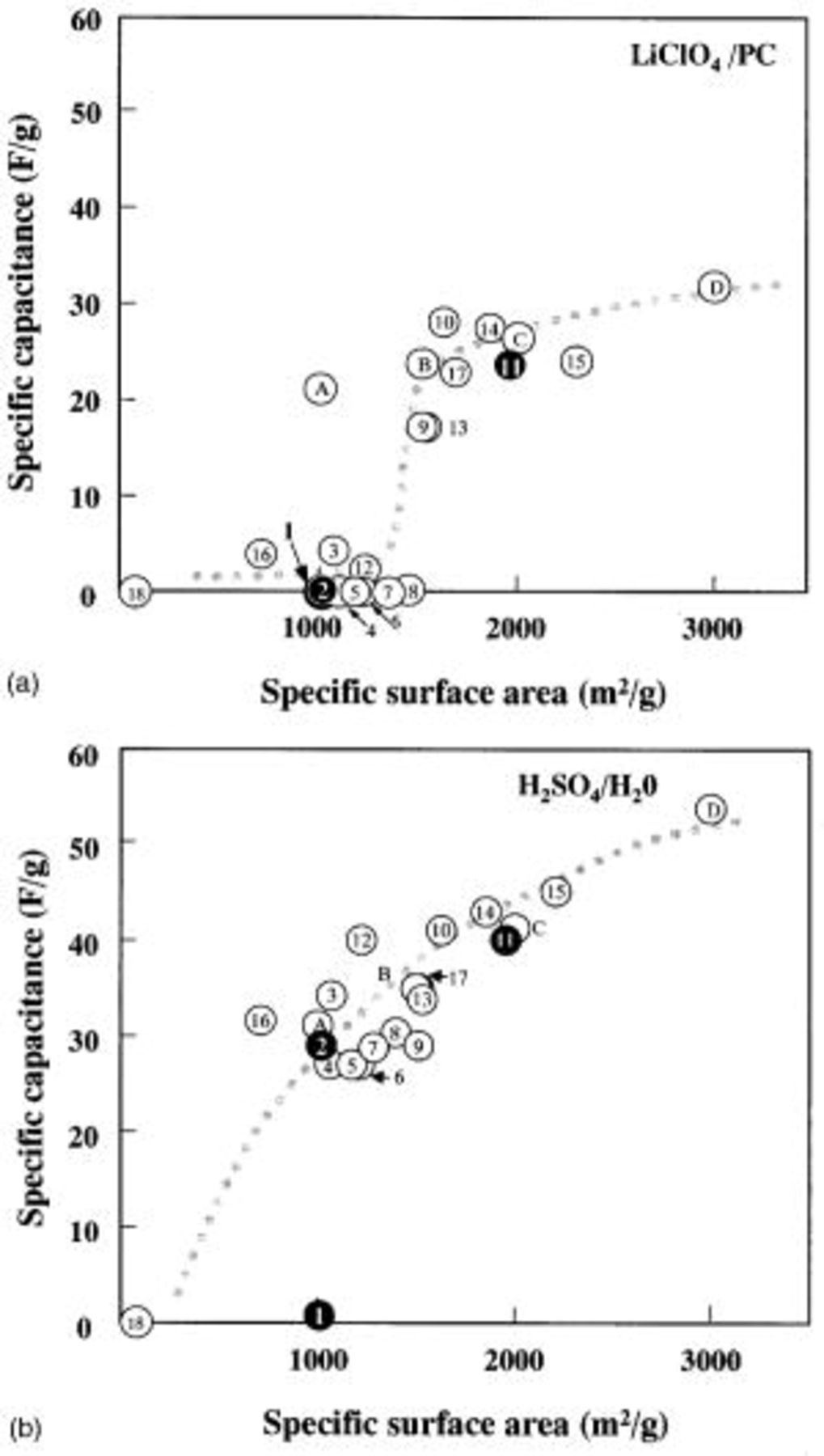
Figure 1. Distribution of the specific capacitance vs. specific surface area for various samples in (a, top) a nonaqueous electrolyte  and (b, bottom) an aqueous electrolyte
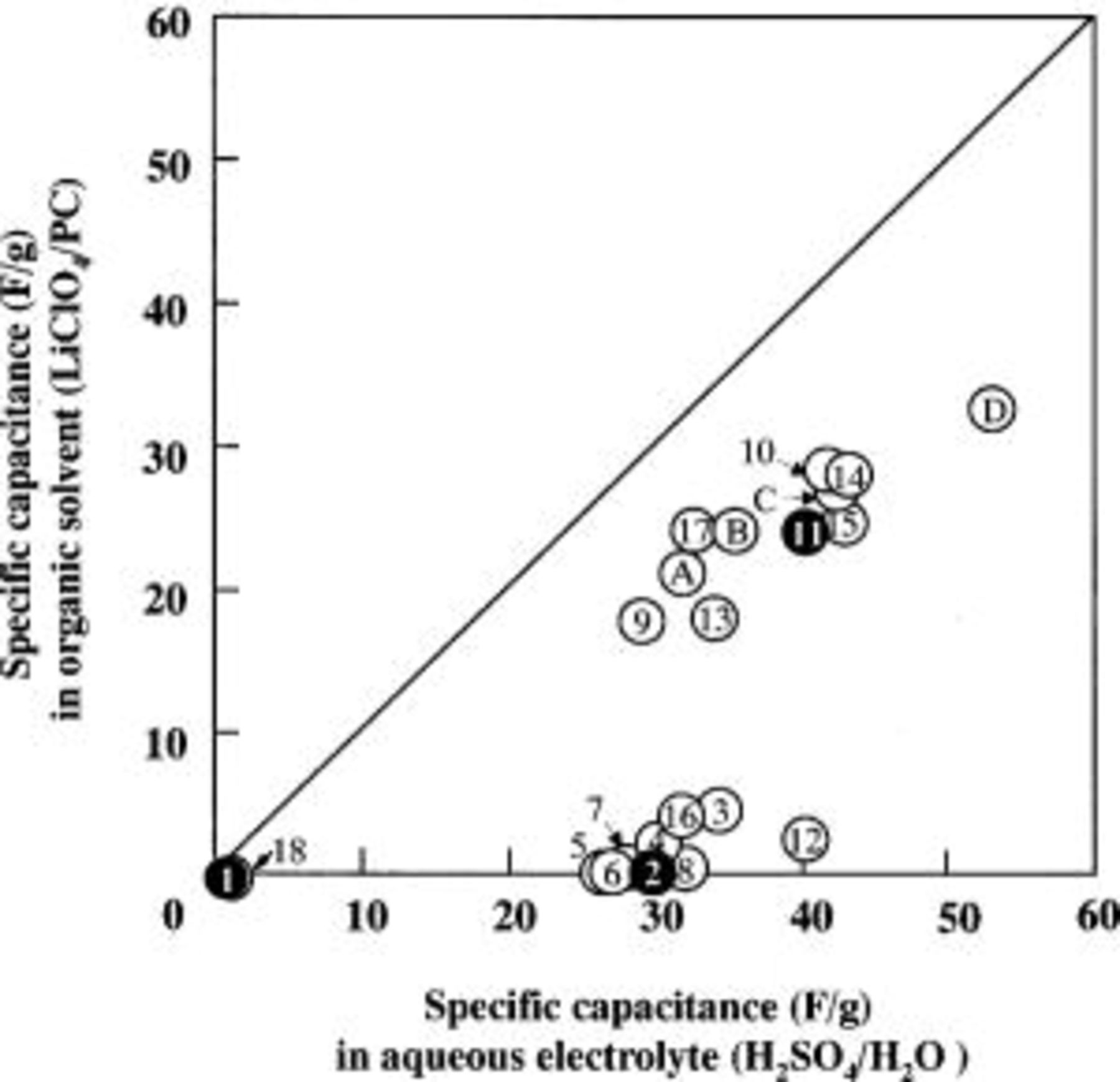
Figure 2. Plot of the specific capacitance of various materials in the  and
and  systems.
Figure 2 shows a plot of the specific gravimetric capacitance in an aqueous electrolyte along the x axis, and the specific gravimetric capacitance in an organic solvent along the y axis. Samples lying on the slope line of 1 indicate that they have the same capacitance in both electrolyte systems. The results shown in Fig. 2 confirm that all data obtained with the ACFs/ACs system show that the aqueous electrolyte system gave higher capacitance than the nonaqueous system. It was further confirmed that most of the capacitance data obtained from these systems have a slope smaller than one, and these data showed quite different electrolyte-dependent results. In the cases that used the aqueous system, a capacitance of more than 20 F/g was obtained for the most part, in comparison to the results for samples using a nonaqueous electrolyte, which show little capacitance. Consequently, we can conclude from these measurements that there is no direct relation between the specific capacitance of the ACF in the two types of electrolytes.
Based on data in Fig. 1 and 2, we classified the 22 samples shown in Table I into three groups as follows: the first group (a typical ACF being sample 11) shows good capacitance for both types of electrolytes, the second group (for example, sample 2) show only good capacitance for the aqueous system, and the third group (for example, sample 1) show no capacitance for either type of electrolyte. Samples 11, 2, and 1 are considered to be representative of each of the three groups.
Figure 3 shows the surface morphology observed by TEM photographs of the three typical samples chosen above. Using the binary image method, the size of the white area for sample 11 is relatively larger in comparison to those of the other samples. Also, the PSD is clarified through the image analysis shown in Fig. 4 for the images in Fig. 3.10 11 In particular, the main pore sizes for samples 11, 2, and 1 are observed to be 30, 20, and 15 Å, respectively. Through these image-analysis results, we could compare the differences between the relative distributions of the pore sizes, but it was impossible to get any quantitative results. At this point, we performed a computer simulation of the possible structures for each group to improve our understanding of the relation between the pore size and the charge-transfer ion size.
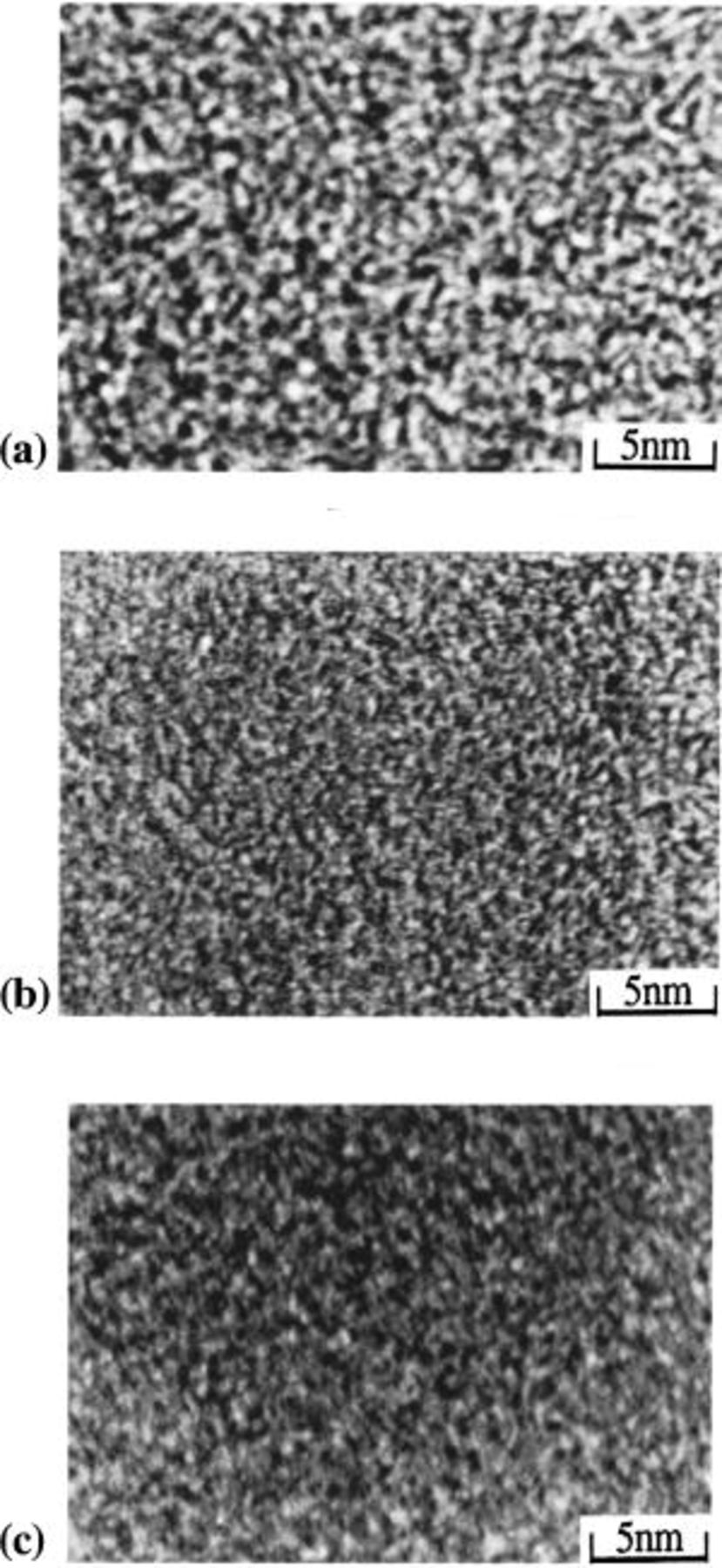
Figure 3. Surface morphology of three representative samples obtained by TEM photography; (a) sample 11, (b) sample 2, (c) sample 1.
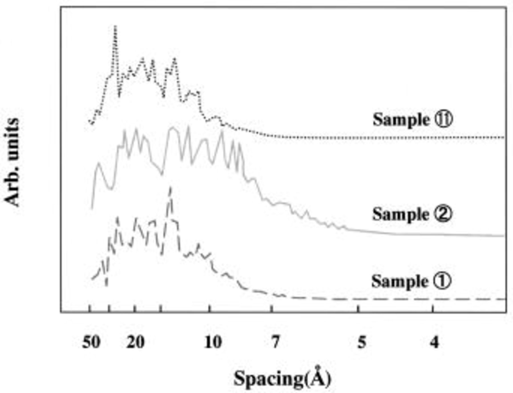
Figure 4. Pore size distribution obtained by the image analyses for each of the TEM photographs in Fig. 3.
Figure 5 shows simulation results of possible features of ion molecules, which control the kinetics in both electrolytes by a size effect. It was assumed that cations do not exist in the electrolyte, because the ion has a smaller size than the pore so that the ion size plays no significant effect on the insertion/deinsertion into the pores of the electrode. First, the  ions can provide a kinetic control parameter in aqueous sulfuric acid, because the cation is smaller than the anion, and the
  ion in a nonaqueous system also can serve as a kinetic control parameter because of the size effect. Therefore, we calculated the possible structure of various electrolyte complexes using a computer simulation (the software Cerius,2 ver. 3.8). The most likely structures of the
  complex can be considered to have six and twelve hydrates using qualitative considerations. Next, the hydration phenomenon was investigated using Cerius2 quantitatively. The computation of the
  ion size was performed on the basis of the heat of formation of
  in water
  and vacuum
  condition using the COSMO method, which calculates a solvent effect using the molecular-orbital method (MOPAC) as an approach. The COSMO method provides a way of approximating a solvent as a continuous uniform medium (dielectric) expressed by a dielectric constant ɛ, and the dielectric constant in water
  was used for the computation. As a result, it was found to be possible to hydrate 12.16 M of
  molecules against 1 M of
  ions, which means that 12.16 water molecules are able to hydrate one
  ion. As mentioned above, the configuration of a sulfate-ion hydrate is devised as follows. Generally, the hydrate becomes more stable, as the number of hydrate ions increases. Therefore, a 12-hydrated sulfate ion was adopted, and this hydrated ion is shown in Fig. 5a.
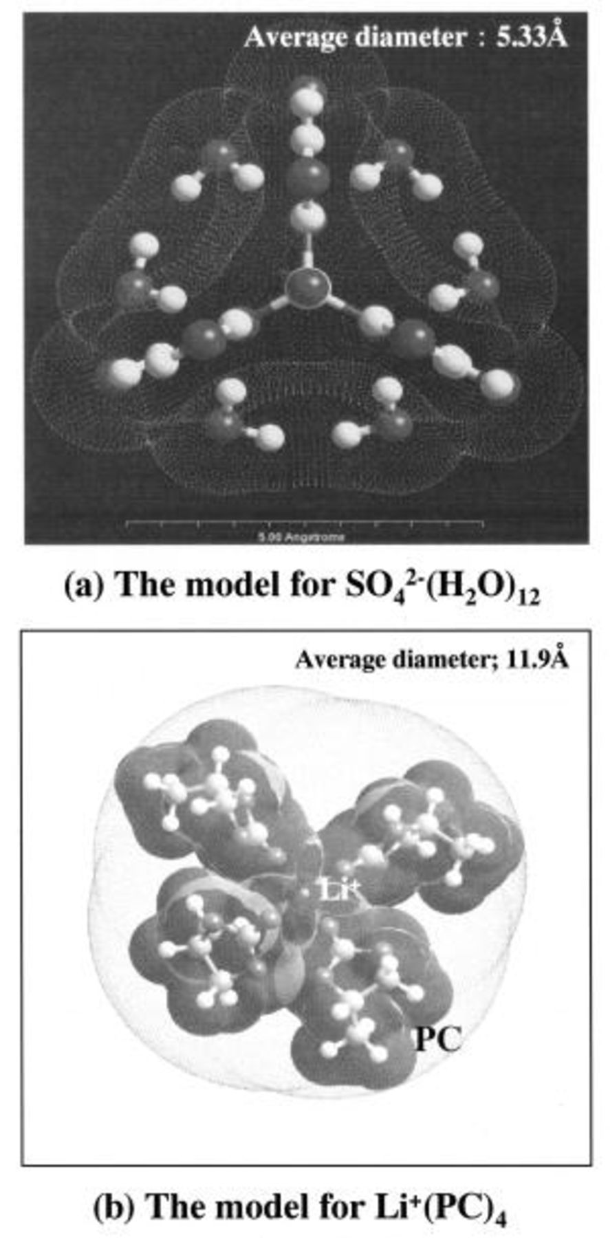
Figure 5. Simulation results of the structures of possible ion complexes in aqueous and nonaqueous systems.
However, unlike other liquids, water has a special configuration, with a big space based on the hydrogen bond. Moreover, the configuration varies on a picosecond  time scale. Therefore, it is thought that the
  ion exists in practice, while rapidly varying between a six-hydration and a 12-hydration configuration.
The calculation with the same method, as was used for the above-mentioned aqueous solution electrolyte, was also used in the  electrolyte system.
  is divided into
  and
and  in solution
  which is a cation, exists in a state of solvation, and becomes attached to
  It is thought that it is through the binding of the
  to the four PCs that a solution bonded with
  is achieved. Moreover, the resulting diameter of the ion brought by the simulation was 11.9 Å (Fig. 5b).
The results thus obtained for the sizes of the two systems were 11.9 Å  in the nonaqueous solvent and 5.33 Å
  in the aqueous system. To help our understanding of the size effect of the electrolyte complex that exists in the two-solvent systems, we suggest the models shown in Fig. 6.
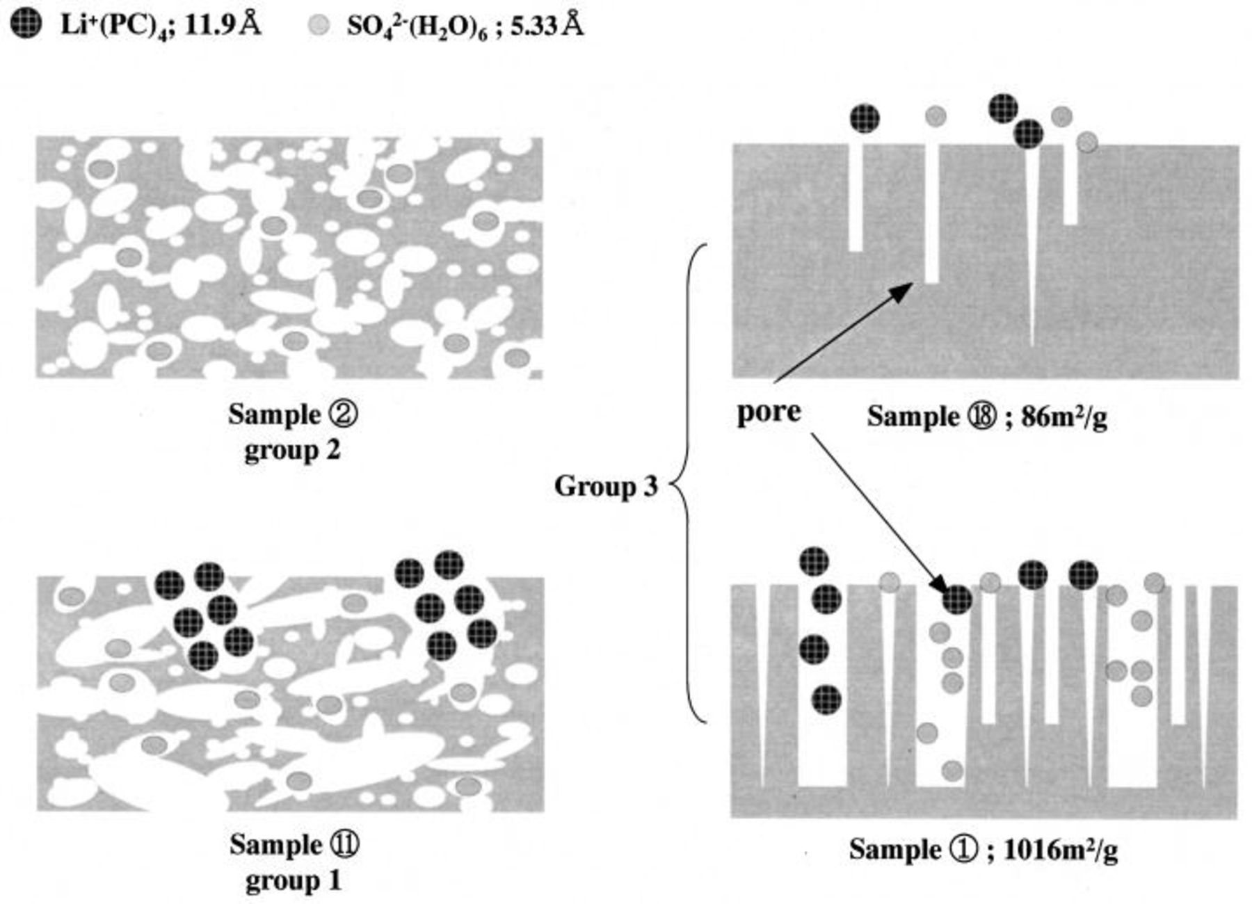
Figure 6. Schematic diagram for the mechanism for the occurrence of capacitance for materials from group 1, group 2, and group 3.
Figure 6 shows a schematic diagram for the mechanism to explain the origin of capacitance in the aqueous and nonaqueous electrolyte systems. The first group (representated by sample 11) shows good capacitance for both types of electrolytes, where large enough pores exist in the electrode allowing penetration of two to three ion complexes of electrolyte into the electrode. Furthermore, a pore size of around two to three times larger than that of the electrolyte complex has been considered as the most suitable pore size for allowing a high capacitance. The second group (represented by sample 2) with a size of 20 Å shows a good capacitance for only an aqueous system. This size is in a range which can barely accommodate a couple of  complexes into the pore of the electrode. So, in the case of a nonaqueous electrolyte, such an ACF sample has a poor capacitance because of the restricted mobility of the
  complex. On the other hand, the aqueous electrolyte ion complexes are small enough to move freely, and are suitable for getting a high capacitance in the electrode pore. Finally, the third group (represented by sample 1) shows no capacitance for either type of electrolyte, which may be due to the small pore size which makes it difficult to obtain a suitable ion arrangement. That is, the pore size range is too small to achieve enough ion mobility. As a result, it is concluded that the pore size distribution has a strong relation to the capacitance achieved in a double-layer capacitor, and also, it is shown that the relationship between the pore size and the ion diameter of the electrolyte greatly affects the capacitance of the double layer.
Conclusions
We evaluated the performance of electrochemical double-layer capacitors using various activated carbon fibers as the electrode in aqueous and nonaqueous electrolytes. The ACFs used in this study are characterized into three groups based on the relationship between their pore size distribution and capacitance. Finally, it is possible to say that the reciprocal relation between the ion diameter of the electrolyte and the pore size of the carbon materials greatly affects the capacitance of the EDLCs.
Shinshu University assisted in meeting the publication costs of this article.