
Abstract
The structure, synthesis, and electrochemical behavior of layered  for
for  5/12, and 1/2 are reported for the first time.
  is derived from
  or
or  by substitution of
  and
and  by
by  while maintaining all the remaining Mn atoms in the 4+ oxidation state.
  with
with  can deliver steady capacities of 150 and 160 mAh/g at 30 and 55°C, respectively, between 3.0 and 4.4 V using a current density of 30 mA/g. Differential scanning calorimetry experiments on charged electrodes of
  for
for  indicate that this material should be safer than
 with
with  5/12, and 1/2 can be cycled between 2.0 and 4.6 V to give capacities of about 200, 180, and 160 mAh/g, respectively, at 30°C.
  with
with  gives a capacity of 220 mAh/g at 55°C between 2.0 and 4.6 V using a current density of 30 mA/g. © 2001 The Electrochemical Society. All rights reserved.
Export citation and abstract BibTeX RIS
Cathode materials help to determine the performance and the safety of Li-ion batteries. The search for a cheaper, higher capacity, and safer layered cathode material than  or
or  is still an ongoing task. Many recent reports address this problem.1
2
3
4
5
6
7
8
9
10
11
12 One very promising cathode material is
is still an ongoing task. Many recent reports address this problem.1
2
3
4
5
6
7
8
9
10
11
12 One very promising cathode material is  7
8
7
8  can deliver a capacity of about 160 mAh/g at ambient temperature and more than 200 mAh/g at 55°C.7 It has a very smooth discharge profile with an average voltage of 3.5 V vs. Li/Li+. Paulsen et al.8 pointed out that
  can be regarded as a solid solution between the layered end members
 and
and  In
In  Cr is in the +3 oxidation state while Mn is in the +4 oxidation state. When Li is extracted electrochemically from the lattice of
  during the charge process,
  is oxidized to
  since Mn cannot, normally, be oxidized beyond 4+ in these materials.
Numata et al.11
12 reported a layer-structure solid-solution cathode material, 
 between
  and
and 


 has the same structure as
  except that there is a superlattice ordering of
  and
and  (1:2) in the transition metal layer, which reduces the symmetry of
  from
from  to
to  13
14 Both
13
14 Both  and
and 
 have
have  or
or  partially replacing
  and
and  in
in  , respectively, while maintaining the remaining Mn atoms in the 4+ oxidation state. Therefore,
  is a member of the series
  with
with  while
while 
 is equivalent to

We found that  can coexist with
  in the transition metal layers of the layered materials
  and
and  6
15
16
17 We show here that
6
15
16
17 We show here that  can replace
  and
and  in
in  to make the layered solid-solution series
 with all Mn atoms expected to be in the 4+ oxidation state. When Li is deintercalated from
  should be oxidized to
  Here, we report the structure, electrochemical, and safety behavior of
  (
( and 1/2).
Experimental
 (98%+, Aldrich),
  (98%+, Fluka), and
  (97%+, Fluka) were used as the starting materials. The samples
  (
( 1/12, 1/6, 1/4, 1/3, 5/12, and 1/2) were prepared by the "mixed hydroxide" method.17 A 50 mL aqueous solution of the transition metal nitrates was slowly dripped (1 to 2 h) into 400 mL of a stirred solution of LiOH using a buret. This causes the precipitation of
 with a homogeneous cation distribution. The buret was washed three times to make sure that all the transition metal nitrates were added to the LiOH solution. The precipitate was filtered out and washed twice with additional distilled water to remove the residual Li salts (LiOH and the formed
  ). The precipitate was dried in air at 180°C overnight. The dried precipitate was mixed with the stoichiometric amount of
  and ground in an automatic grinder. Pellets about 5 mm thick were then pressed. The pellets were heated in air at 480°C for 3 h. Tongs were used to remove the pellets from the oven and sandwich them between two copper plates in order to quench the pellets to room temperature. The pellets were ground and new pellets made. The new pellets were heated in air at 900°C for another 3 h and quenched to room temperature in the same way.
X-ray diffraction (XRD) was made using a Siemens D500 diffractometer equipped with a Cu target X-ray tube and a diffracted beam monochromator. Profile refinement of the collected data was made using Hill and Howard's version of the Rietveld program Rietica.18
"Bellcore-type" electrodes were prepared for the electrochemical tests. z grams of the sample is mixed with ca. 0.1z (by weight) super S carbon black and 0.25z Kynar 2801 [poly(vinylidene fluoride)-hexafluoropropylene, Elf-Atochem]. This mixture was added to 3.1z acetone and 0.4z dibutyl phthalate (DBP, Aldrich) to dissolve the polymer. After several hours of stirring and shaking, the slurry was then spread on a glass plate using a notch bar spreader to obtain an even thickness of 0.66 mm. When the acetone evaporated, the dry films were peeled off the plate and punched into circular disks of 12 mm diam. The punched electrode was washed several times in anhydrous diethyl ether to remove the DBP. The washed electrode was dried at 90°C overnight in air before use. Using the above positive electrodes, 2325 type coin-cells (23 mm diam, 2.5 mm thick) were assembled in an argon glove box (
 ) with lithium as the anode, Celgard 2502 membrane as the separator, and 1 M
  in 33% ethylene carbonate
  diethyl carbonate (DEC) (Mitsubishi Chemical) as the electrolyte. Usually, the cathode mass was around 20 mg. The cells were tested using constant charge and discharge currents between the desired potential limits.
Results and Discussion
Figure 1 shows typical X-ray diffraction (XRD) patterns of  (
( 5/12, and 1/2) with Miller indices indicated. All of the peaks can be indexed based on a hexagonal
  structure (space group:
  166), except for a very broad peak between 20 and 25°. This broad peak is thought to be caused by short-ranged superlattice ordering of the Li, Ni, and Mn atoms in the transition metal layers. The broad peak has also been observed in examples from Ref. 8, 11, and 12. The superlattice peak is difficult to detect for the sample
  since there is very little Li in the transition metal layers. For convenience, the structure of
  is considered to be isostructural to
  Figure 2 shows the lattice parameters (a and c), and the
  ratio as a function of x in
  Both a and c increase linearly with Ni content but the
  ratio decreases. Such a behavior suggests a substitution of
  for
for  and
and  in a solid solution.
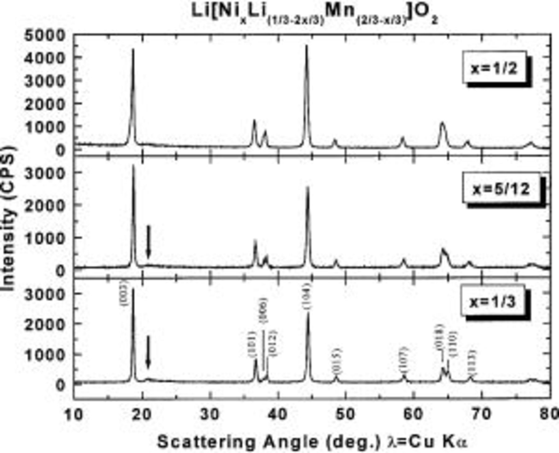
Figure 1. XRD profiles of  with
with  5/12, and 1/2 as indicated. The Miller indices of the peaks are indicated in the lower panel. The arrows designate the position of a short-range order superstructure peak.
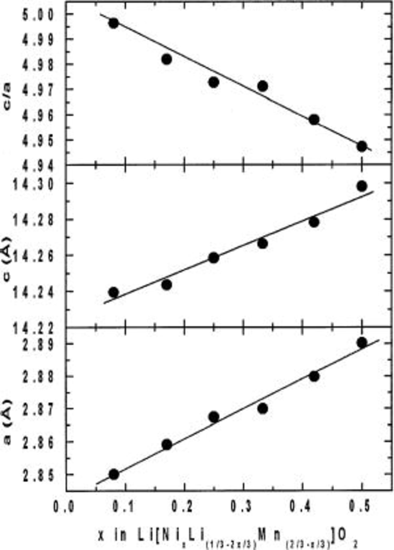
Figure 2. Lattice constants and  ratio of
  vs. x.
Figure 3a shows the voltage vs. capacity for 
 cells between 3.0 and 4.4 V vs.
  using a specific current of 30 mA/g. This corresponds to a current density of about 0.5 mA/cm2.
  with
with  has a very smooth charge/discharge curve and an average potential of about 3.85 V. The irreversible capacity loss is only about 15 mAh/g, which is about 10% of the first charge capacity. Figure 3b shows the capacity vs. cycle number for a
  cell
cell  at 30°C and then at 55°C.
 can deliver a capacity of 150 mAh/g at 30°C and a capacity of about 160 mAh/g at 55°C.
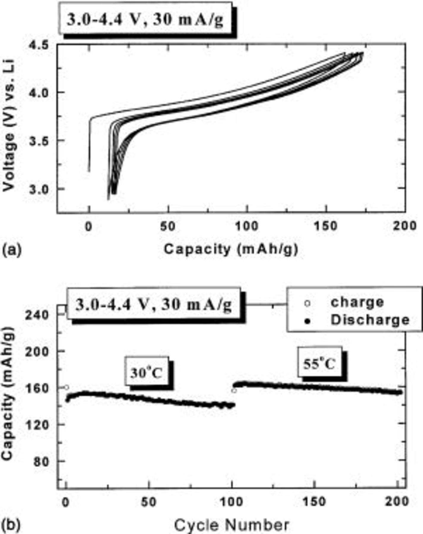
Figure 3. (a) Voltage vs. capacity of a  cell with
  (b) Capacity vs. cycle number for a
  cell with
Figure 4 shows voltage vs. capacity for a 
 cell discharged at a variety of currents. The cell was charged using a current of 5 mA/g before each discharge test. A capacity of over 140 mAh/g at an average voltage of about 3.5 V is delivered at 400 mA/g. After the rate capability testing, the electrode was charged to 4.4 V at 5 mA/g and discharged to 2.0 V at 5 mA/g. The cell still had a capacity of 171 mA/g, the same as at the start of the experiment.
  with
with  has very good rate capability.
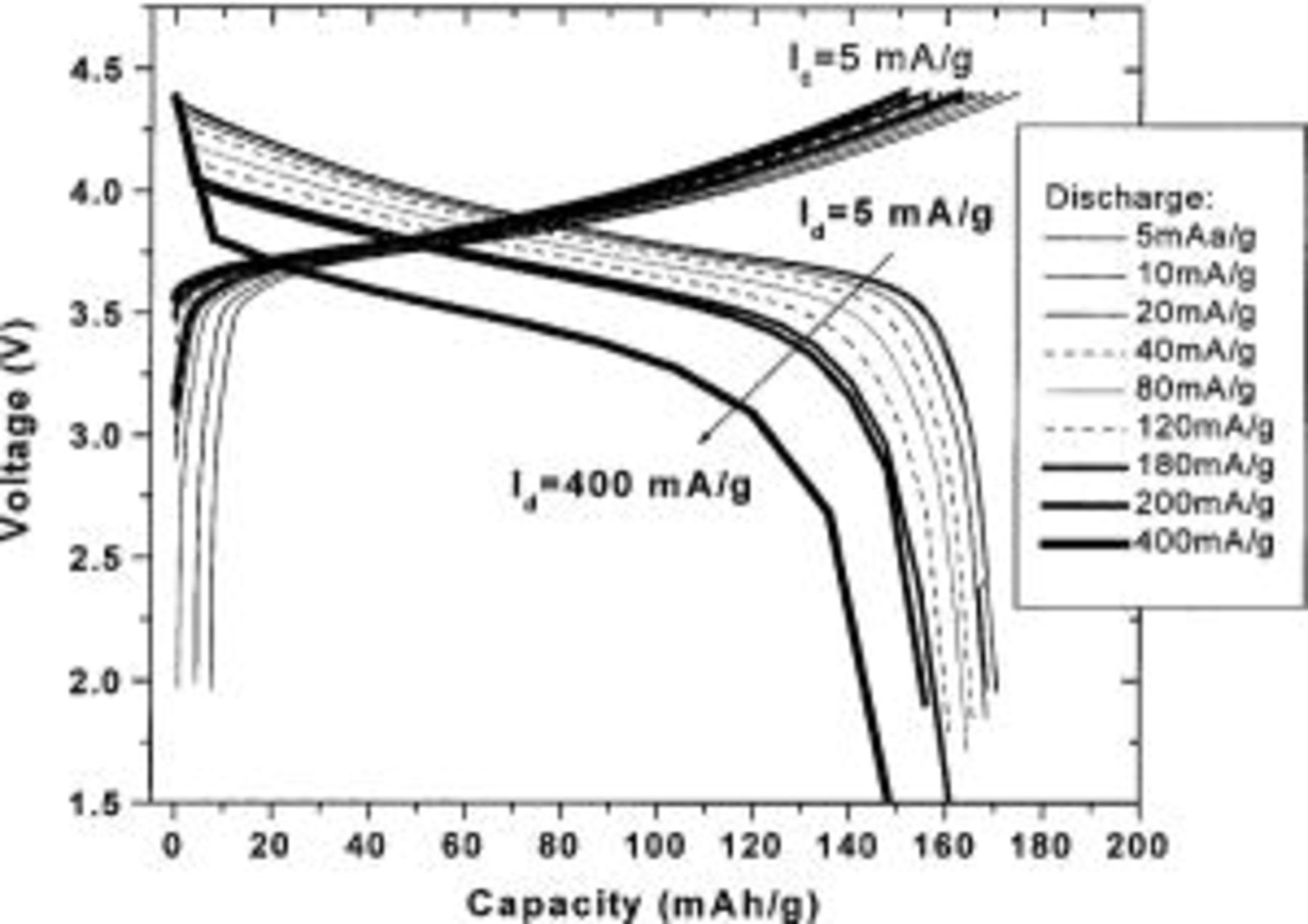
Figure 4. Voltage vs. capacity of a  cell with
  discharged at various currents.
Figure 5 shows the voltage vs. capacity of  cells with
  5/12, and 1/2 between 2.0 and 4.6 V. These electrodes were first charged to 4.8 V using a specific current of 5 mA/g (see dashed line), then were cycled between 2.0 and 4.6 V. The current density was initially 5 mA/g (2 cycles, dashed line), then 10 mA/g (2 cycles, thin solid line), and finally, 30 mA/g (50 cycles, thick solid line). There is an irreversible plateau around 4.5 V (marked by the arrows in Fig. 5) during the first charge which disappears during the following cycles. The plateau length decreases as x increases. It is believed that the plateau is not due to the decomposition of the electrolyte. The capacity before the plateau (up to 4.45 V) during the first charge is very close to the theoretical capacity of
  assuming that all the
  is oxidized to
  when the Li is extracted. We speculate that during the plateau electrons are removed from the oxygen atoms in the structure leading to a partial loss of oxygen from the electrode. When lithium is inserted back into the structure of the electrode (subsequent to the charge to 4.8 V), after all
  is reduced into
  a portion of the
  is apparently reduced to
  by the further inserted Li. The capacity due to the Mn reduction is shown as a plateau near 3.3 V in the voltage profile.
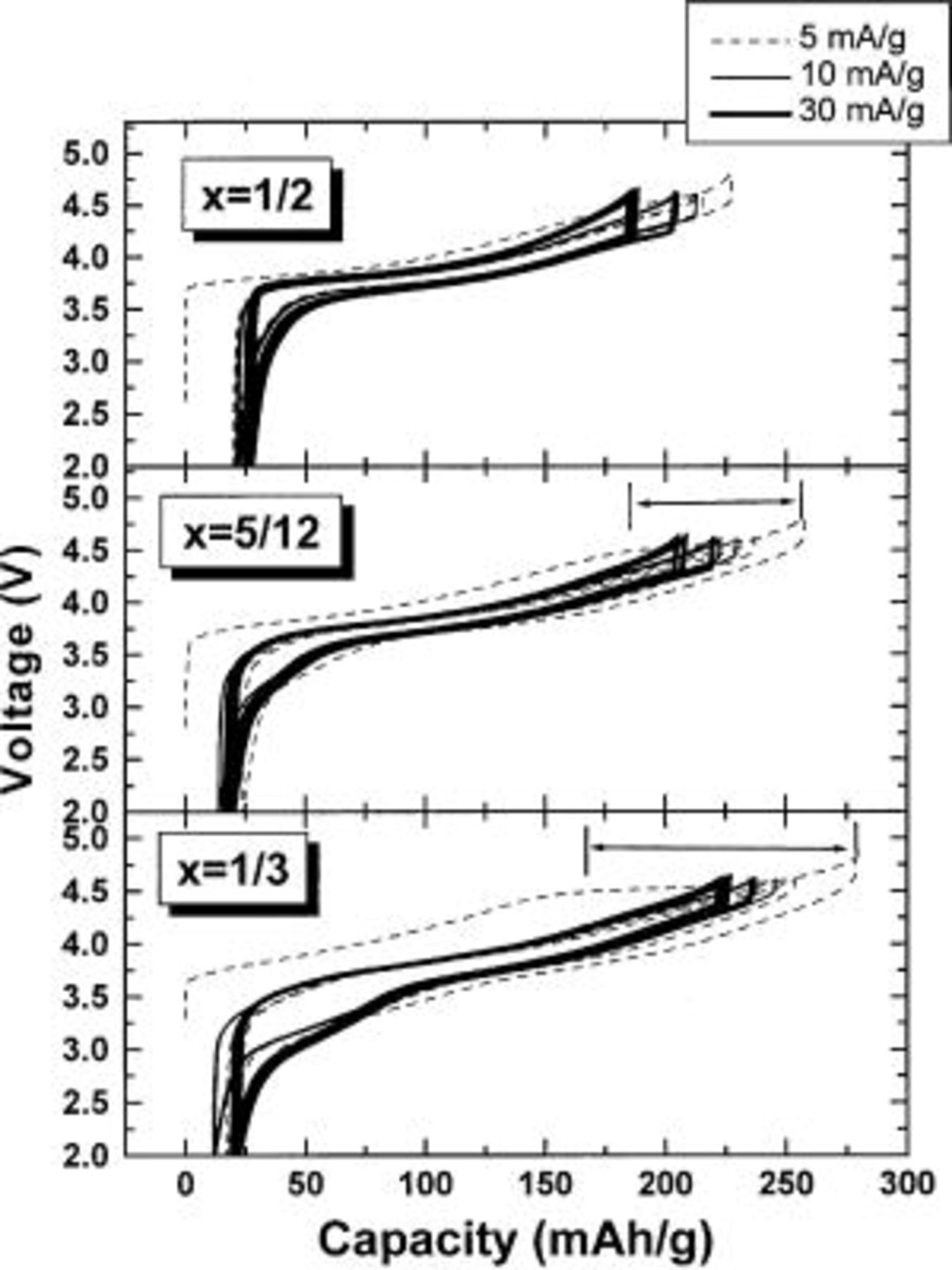
Figure 5. Voltage vs. capacity of  cells having
  5/12, and 1/2 as indicated. The cells were first charged to 4.8 V during the first cycle and then cycled between 2.0 and 4.6 V using currents as indicated by the legend.
Figure 6 shows the capacity vs. cycle number for  cells with
  5/12, and 1/2. The electrodes with
  5/12, and 1/2 can deliver stable capacities of about 200, 180, and 160 mAh/g, respectively, between 2.0 and 4.6 V. Figure 7 shows the capacity vs. cycle number for the electrode with
  at 55°C after the cell had been cycled 50 times first at 30°C. The electrode with
  can still deliver a steady capacity of about 220 mAh/g.
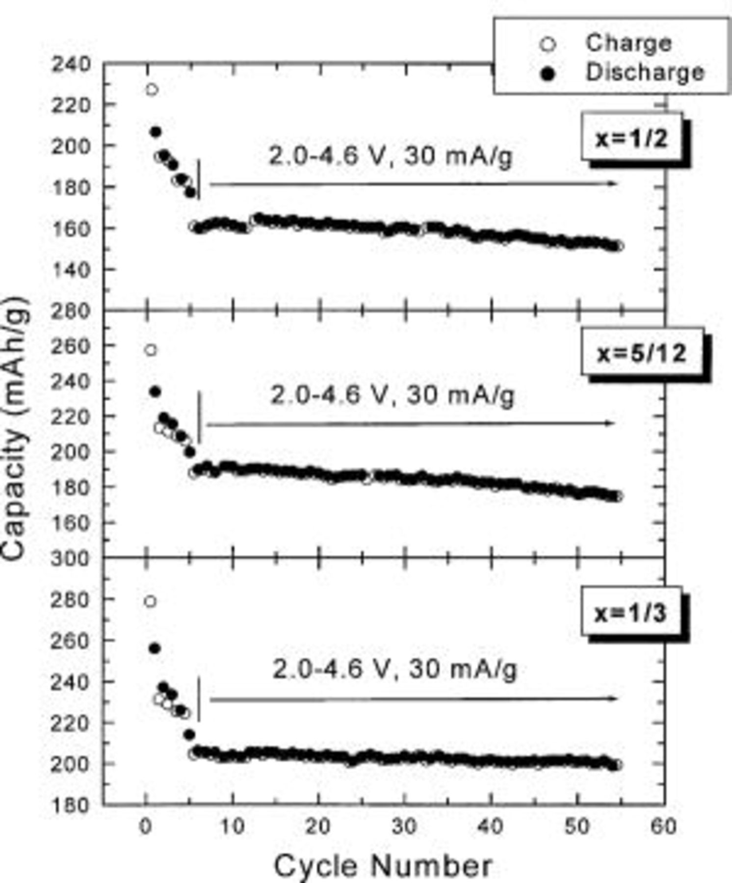
Figure 6. Capacity vs. cycle number for  cells having
  5/12, and 1/2 as indicated.
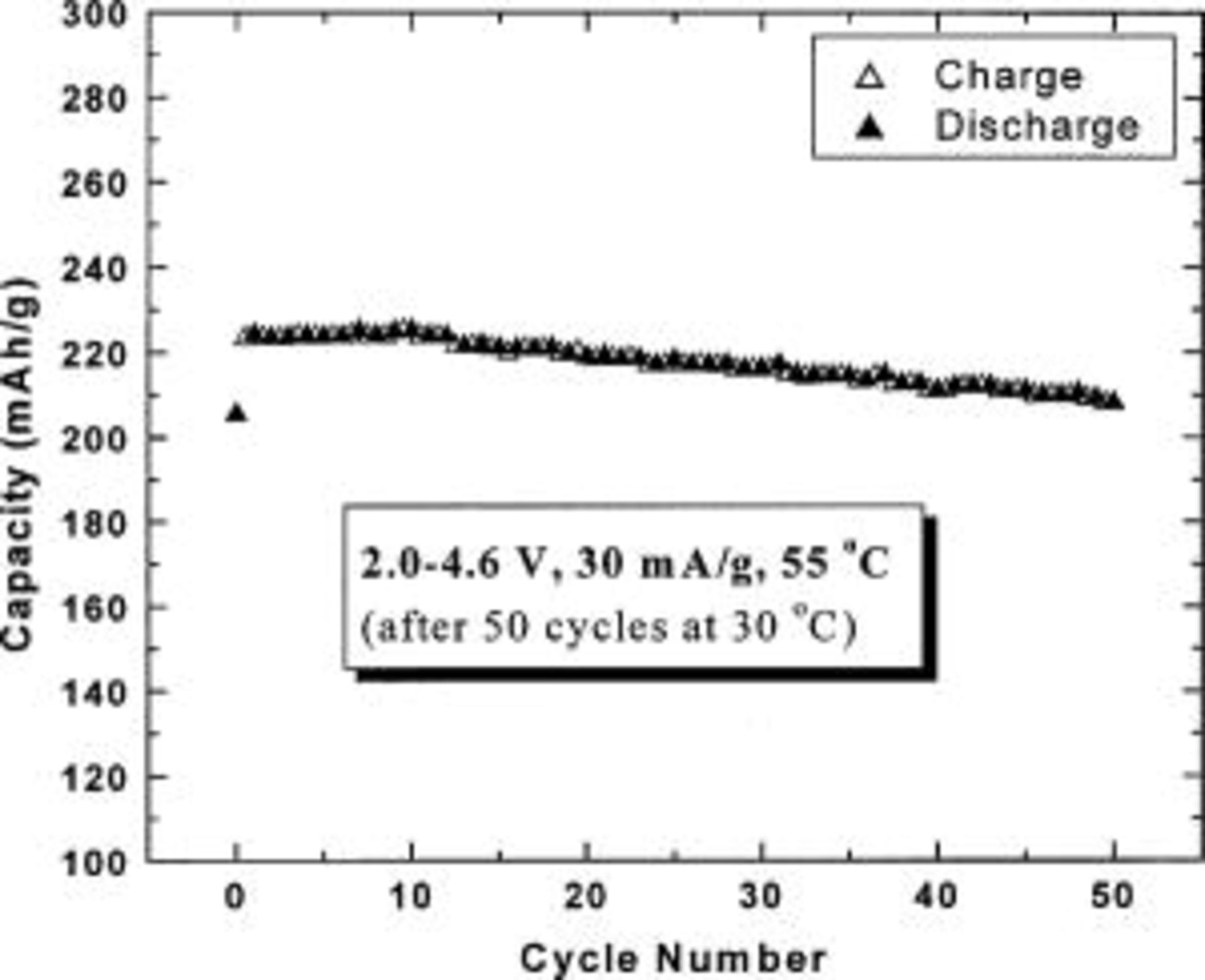
Figure 7. Capacity vs. cycle number for a  cell with
  as indicated in the legend.
Figure 8 shows the differential scanning calorimetry (DSC) profiles of wet electrodes of  with
with  which was charged to 4.2, 4.4, 4.6, or 4.8 V in a lithium coin cell with an electrolyte of 1 M
  (33:67%). The DSC experiments were made in welded sealed stainless steel tubes so that no leaking of pressurized electrolyte is possible.19 The capacity indicated in each panel of Fig. 8 indicates the amount of Li extracted from the electrode. The heat associated with each exothermic peak is also indicated on the panels of Fig. 8. The onset temperature of the main exothermic peak is above 260°C provided that the charge potential is less than 4.4 V vs. Li. When the charge potential is 4.4 V, there is a small peak between 240 and 260°C, but it only produces 205 J/g of heat. When the electrode is charged above 4.5 V, the thermal properties are quite different from those when the charge potential is less than 4.4 V. First, there is a lower temperature exothermic peak between 200 and 230°C. Second, the strongest exothermic peak becomes broad and is distributed between 240 and 280°C (for 4.6 V) or its onset temperature moves to a lower temperature (for 4.8 V).
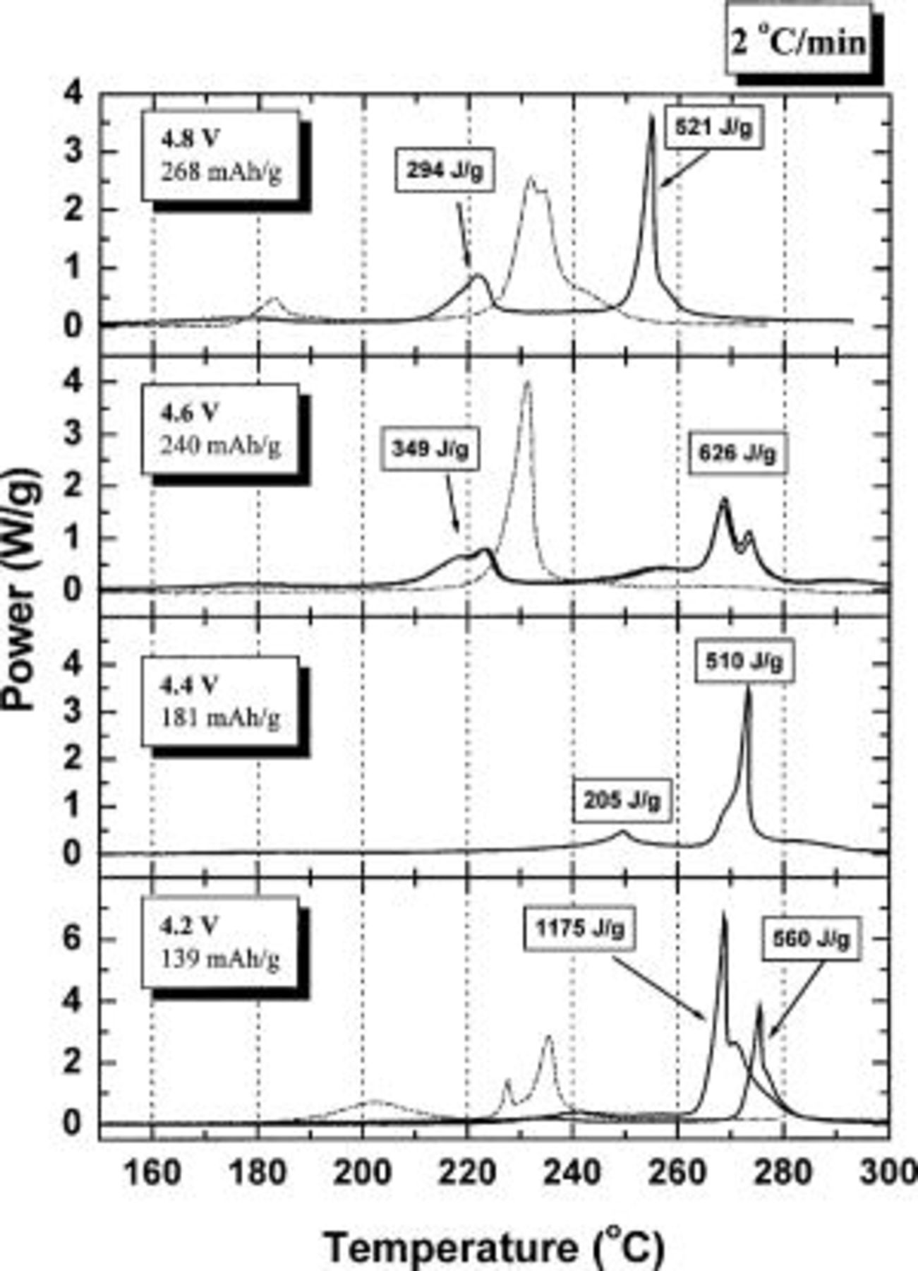
Figure 8. DSC profiles (2°C/min) of charged 
 electrodes at the indicated potentials. Some experiments were duplicated. The experiments were conducted using welded stainless steel pans to eliminate all leaking. Comparison results for
  electrodes charged to the same potentials is given as the dashed curves where data is available. The Brunauer, Emmett, Teller surface area of the
  sample was 5.0 m2/g and that of the
  was 0.2 m2/g.
As a comparison, battery grade  (FMC) was charged to 4.2 V and delivered a capacity of about 130 mAh/g. The onset temperature of the exothermic peak of the DSC curve of the wetted
  electrode (charged to 4.2 V) measured by the same methods is 185°C20 and produced a total heat of about 700 J/g.20 Therefore,
  with
with  is safer than
  if the charge potential is less than 4.4 V vs.
Conclusions
 with
with  5/12, and 1/2 can be synthesized by the mixed hydroxide method. This solid solution represents
  substitution for
  and
and  in
in  while maintaining all the remaining Mn atoms in the
  oxidation state. The electrochemical performance of
  with
with  at both 30 and 55°C is excellent. DSC results for wetted and charged electrodes of
  with
with  indicates this material would be at least as safe as
  if its charge potential were below 4.4 V.
  with
with  5/12, or 1/2 can be cycled between 2.0 and 4.6 V to give a stable capacity of about 200, 180, or 160 mAh/g, respectively, at 30°C. During the first charge to 4.8 V of these materials, an irreversible plateau was observed around 4.5 V.
  with
with  can give a stable capacity of 220 mAh/g at 55°C between 2.0 and 4.6 V using a specific current of 30 mA/g.
Clearly, these materials warrant further study in prototype Li-ion cells. They contain no cobalt, do not convert to the spinel phase, and are easily prepared. Their electrochemical and safety characteristics are comparable or better than 
Acknowledgment
The authors acknowledge the support of NSERC, 3M Co., and 3M Co., Canada, for the funding of this work.
Dalhousie University assisted in meeting the publication costs of this article.