Abstract
Lithium phosphorous oxynitride (Lipon) films were deposited in  gas atmosphere with different radio-frequency magnetron sputtering power from 80 to 160 W with 20 W step increase. Lipon films deposited at lower sputtering power showed higher ionic conductivities than the films deposited at higher sputtering power. The results of impedance measurements showed that nitrogen incorporation into the glass structure increased the ionic conductivity and this nitrogen content in the Lipon films increased as the sputtering power decreased. In addition, the Auger electron spectroscopy depth profile showed that the increased nitrogen content in the Lipon films was not the result of the target surface poisoning effect but the result of reactive incorporation of nitrogen. © 2001 The Electrochemical Society. All rights reserved.
Export citation and abstract BibTeX RIS
The miniaturization of electronic devices has resulted in very low current and power requirements for many applications [complementary metal oxide semiconductor (CMOS) CMOS back up, smart cards, implantable medical devices, microelectromechanical system (MEMS)]. Microenergy sources must be developed to drive these small electronic devices. A thin film battery (TFB) is one of the options for satisfying this demand. To make the thin film battery, a thin film solid electrolyte is indispensable.
Solid electrolytes have several advantages over liquid electrolytes, such as no leakage problem, broad operating temperature range, excellent charge-discharge cyclic properties due to a lack of side reactions occurring and only one type of carrier ion migration, and long life because of little self-discharge. Such solid electrolytes should have properties such as a very high ionic conductivity, negligible electronic conductivity, and a very low activation energy.
Ion conducting glasses are generally composed of three components, a network former, a network modifier, and a doping salt. The absence of structural constraints allows easy modification of their relative contents to optimize electrical and electrochemical properties. They are usually made by conventional melt-quenching.
Based on this theory, several solid electrolytes were studied such as  1
1  2
2  3
3  4
5
6
7
8
9
4
5
6
7
8
9  10
10  11
11  12
13
12
13  14
14  15
15  16
16  17 Among these,
  - based solid electrolytes are unstable in contact with Li metal used as an anode and also unstable in atmosphere, although they show high ionic conductivities. On the other hand, while
  -based solid electrolytes are easy to handle in atmosphere, they show low ionic conductivities and the stability problem with Li metal contact is not solved.
Recently, a new  ion conducting solid electrolyte lithium phosphorous oxynitride (Lipon) was developed and has been successfully incorporated into rechargeable thin-film lithium batteries by Oak Ridge National Lab.18
19 This material is stable with Li metal, easy to handle in atmosphere and shows high ionic conductivity. This amorphous material is deposited by sputtering
ion conducting solid electrolyte lithium phosphorous oxynitride (Lipon) was developed and has been successfully incorporated into rechargeable thin-film lithium batteries by Oak Ridge National Lab.18
19 This material is stable with Li metal, easy to handle in atmosphere and shows high ionic conductivity. This amorphous material is deposited by sputtering  in
in  gas, and its composition can be represented by
  where PON is phosphorus oxynitride. Lipon films prepared in this way show high ionic conductivity
  at 25°C, the stability window up to 5.5 V and low activation energy (0.55 (±0.22) eV). It was suggested that the incorporation of N into the amorphous structure of
  contributed to the enhancement of ionic conductivity. They also proposed the structure of Lipon using electron spectroscopy for chemical analysis in another report.20
In this study, we focused on enhancing the ionic conductivity by changing radio-frequency (rf) magnetron sputtering power and on suggesting the reactive sputtering mechanism. Because this process is reactive sputtering, the change of the rf magnetron sputtering power was thought to change the film composition, and we tried to see how the film composition affects the ionic conductivity.
Experimental
Target preparation.—
 powder (Aldrich) was used to make a
  target. The powder was first calcined at 850°C for 3 h in a furnace (Lindberg). The calcined powder was ground and sieved (60 mesh) and then ballmilled with zirconia ball in anhydrous ethyl alcohol for 24 h. To make it easy to press the target, a small amount of polyvinylbutyral (PVB, Monsanto, 1 wt % of
  powder) was added during the ballmilling process (after 12 h from the start of ballmilling).
After ballmilling, ethyl alcohol was dried at 80°C for 24 h in drying oven. The dried powder was ground, sieved, and pressed with force of 100 kg/cm2.
The pressed target was sintered at 600°C for 3 h and then at 950°C for 3 h. The duration step at 600°C is for the elimination of PVB. The sintered target was finally shaped into the 4 in. target.
Thin film deposition.—
Si wafer [100] was cleaned with trichloroethylene, acetone, and anhydrous methyl alcohol. Ti and Pt films were then deposited by dc-sputtering sequentially where Ti acts as a barrier layer for improving adhesion of Pt on the Si wafer.
Lipon films were deposited by rf magnetron sputtering in  gas atmosphere. The initial pressure was
  and the working pressure was
  The power was enhanced from 80 to 160 W by 20 W step increase.
Li was deposited by thermal evaporation on the Lipon thin films for the impedance measurements.
Electrochemical and compositional analysis.—
The surface morphology and cross-sectional views of the deposited Lipon thin films were observed by scanning electron microscopy (SEM) imaging (Hitachi S-4100). The compositions of the films were determined from inductively coupled plasma-atomic emission spectrometry (ICP-AES, Therrellash Polyscan61E), atomic absorption spectrophotometry (AAS, Varian SpectraAA800) (Li/P ratios), and Rutherford backscattering spectrometry (RBS, NEC 6SDH-2) (N/O/P ratios).
The impedance and the activation energies of the films were measured by IM6 (Zahner Elektrik). The frequency range used is from 100 mHz to 1,000,000 Hz. The area of the Li electrodes is 1 cm2. The compositional depth profile of the film was shown by Auger electron spectroscopy (AES, Perkin Elmer PHI-670). The  ion sputtering energy for AES is 3.5 kV. This corresponds to etching rate of 160 Å/min
Results and Discussion
Figure 1 shows the SEM images of the deposited Lipon films. Figure 1a shows the surface of the Lipon film and Fig. 1b is the cross-sectional view of the film. These two images show uniform and clean surfaces for the films as well as the compact structure. The Pt current collector and Ti barrier layer can be seen in Fig. 1b. The images also show that the Lipon film showed good adherence to the Pt layer.
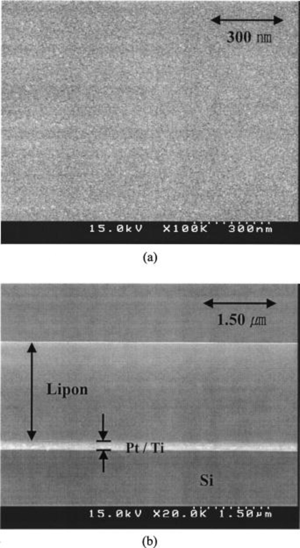
Figure 1. (a) Surface SEM image of the Lipon, (b) cross-sectional view of the Lipon film deposited at 80 W. Other Lipon films deposited at other rf sputtering power showed similar morphologies.
Figure 2 shows the impedance spectra of the Lipon films. They show the typical solid electrolyte impedance spectra. While the impedance responses of low frequencies, dominated by the electrode-electrolyte interface response,21 enhance the frequency range as the power decreases, those of high frequencies, which are the responses of the electrolyte film, do not change the frequency range much, compared with those of low frequencies. This means that Lipon films are stable by themselves, but the electrode-electrolyte interface layer is formed easily as the Lipon films are deposited at lower sputtering power. Therefore, decreasing the sputtering power may be bad for the cycling of lithium batteries while increasing the ionic conductivities.
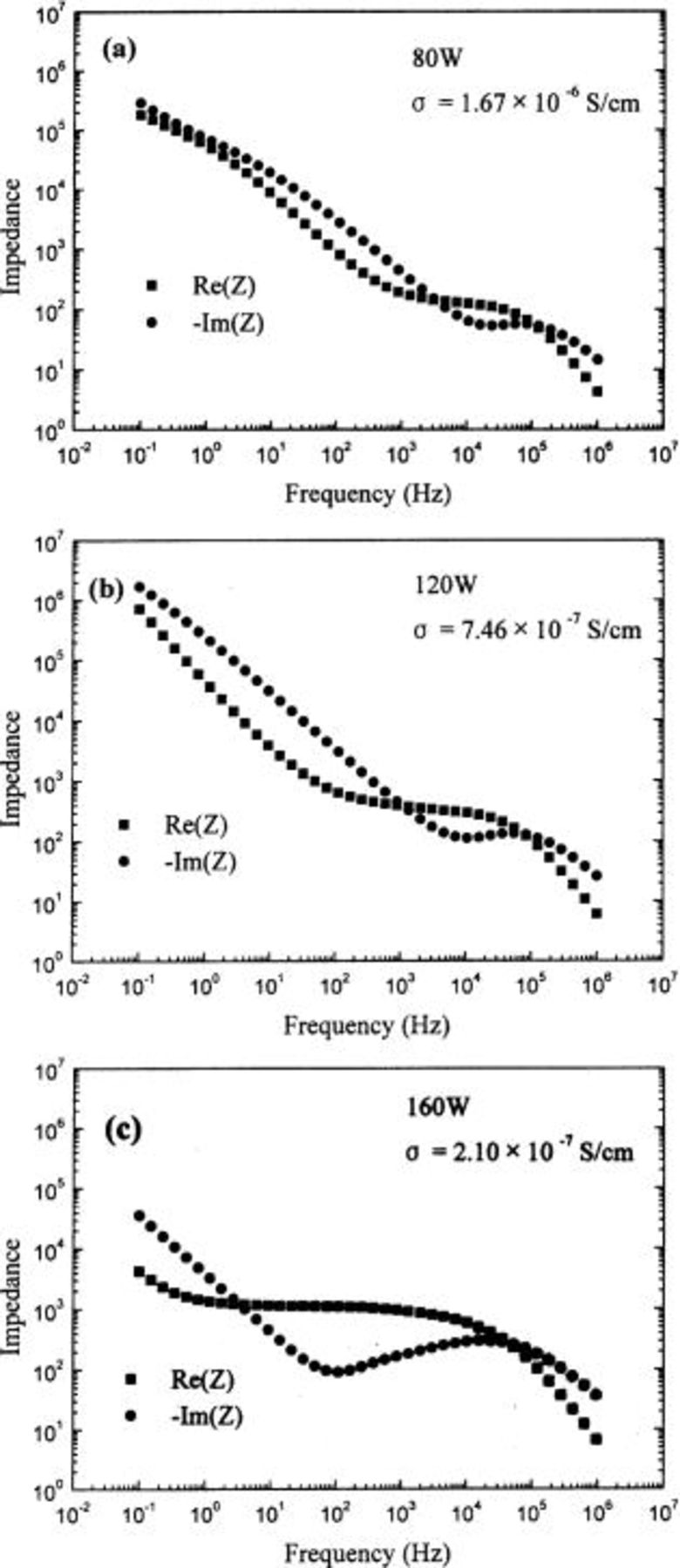
Figure 2. Impedance spectra of the Lipon films deposited at (a) 80, (b) 120, and (c) 160 W which have the structure of Li/Lipon/Pt. They show the typical solid electrolyte impedance.
The CPA model22 was used as an equivalent circuit to determine the Lipon thin film impedance. The ionic conductivities were determined by using  where d is the film thickness, A is the area of the metal contact, and R is the film resistance determined from impedance spectroscopy. These calculated ionic conductivities are shown in Table I.
Figure 3 is the result of least squares fit of the Arrhenius equation  of experimental data for the Lipon films, where σ is the ionic conductivity, T is the temperature,
  is the activation energy, and κ is the Boltzmann constant. The temperature range varies from 5 to 95°C. The slope becomes steeper as the rf sputtering power increases, that is, the activation energies of Lipon films increase as the rf sputtering power increases. The average
  0.537 eV corresponds to the result of the previous experiment.21
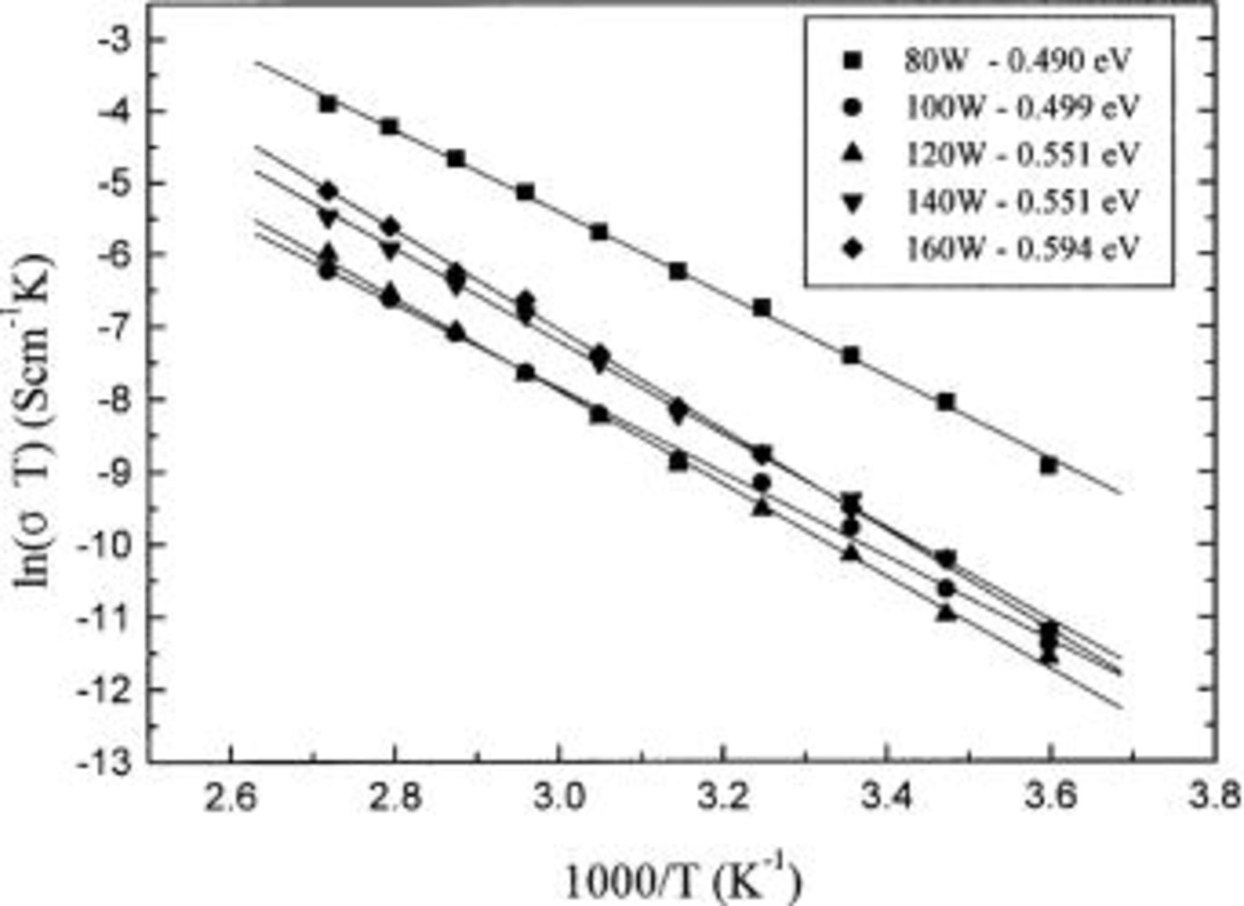
Figure 3. Arrhenius plot of ionic conductivity of Lipon deposited at rf power of 80-160 W vs. temperature. The slope becomes steeper as the power increases.
These results show that the ionic conductivities of Lipon films increase and the activation energies decrease as N content in the films increases and the rf magnetron sputtering power decreases. We speculate that the reason N content in the Lipon films increases as the power decreases is the result of increase of sputtering time, because the sputtering time must be increased to deposit the films above certain thickness to prevent short circuits. This is because solid electrolytes act as separators as well as ion conductors. Therefore, to deposit the films above a certain thickness, the sputtering time must be increased when the rf magnetron sputtering power decreases. As a result, the time that nitrogen can incorporate into the Lipon films increases.
From these results, the reactive sputtering process can be thought as follows Step 1
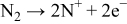
Step 2

Step 3


In these, the first and third steps are fast because the first step occurs whenever plasma occurs, and the first reaction in the third step occurs with strong momentum energy, and the last two reactions in the third step are the binding of electrons and positive ions. Therefore, the reaction time of the second step increases by reducing rf sputtering power, which results in the increase of nitrogen contents in the Lipon films.
Here, it should be noted that the quantity of nitrogen ions that are decomposed in the first step may be increased by increasing the rf sputtering power, but the nitrogen content which incorporates into the Lipon films must be negligible compared with the reaction time effect by changing rf sputtering time.
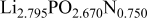
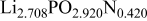
The composition, ionic conductivity, deposition rate, and activation energy of the Lipon films are shown in Table I. The ionic conductivity of Lipon films increases as the rf magnetron sputtering power decreases, and these results have been compared with the N/P ratios of the Lipon films deposited with different powers. Here, we see that the ionic conductivity of Lipon films changes linearly with N/P ratios or N contents in the Lipon films.
Table I.
| Compositions, ionic conductivities, deposition rates, and activation energies for Lipon films deposited at 80-160 W. | ||||||
|---|---|---|---|---|---|---|
| Li/P ratio | N/Pratio | Ionicconductivity (S/cm) | Depositionrate (Å/h) | Activation energy (eV) | Whole composition | |
| 80 W | 2.971 | 1.250 |
 | 872 |
 |
 |
| 100 W | 2.41 | 0.909 |
 | 1276 |
 |
 |
| 120 W | 2.795 | 0.750 |
 | 1936 |
 |
 |
| 140 W | 2.708 | 0.420 |
 | 2389 |
 |
 |
| 160 W | 2.854 | 0.400 |
 | 2759 |
 |

|
Figure 4 shows the AES depth profile of the Lipon film. The nitrogen content in the film does not change with the depth. The result shows that the nitrogen in the Lipon film was incorporated into the films uniformly during the reactive sputtering, not by the poisoning effect of the target surface. If the nitrogen incorporation into the film were accomplished by the poisoning effect of the target, the nitrogen content in the film would have increased as the film was deposited because the nitrogen content on the target surface would have increased with time.
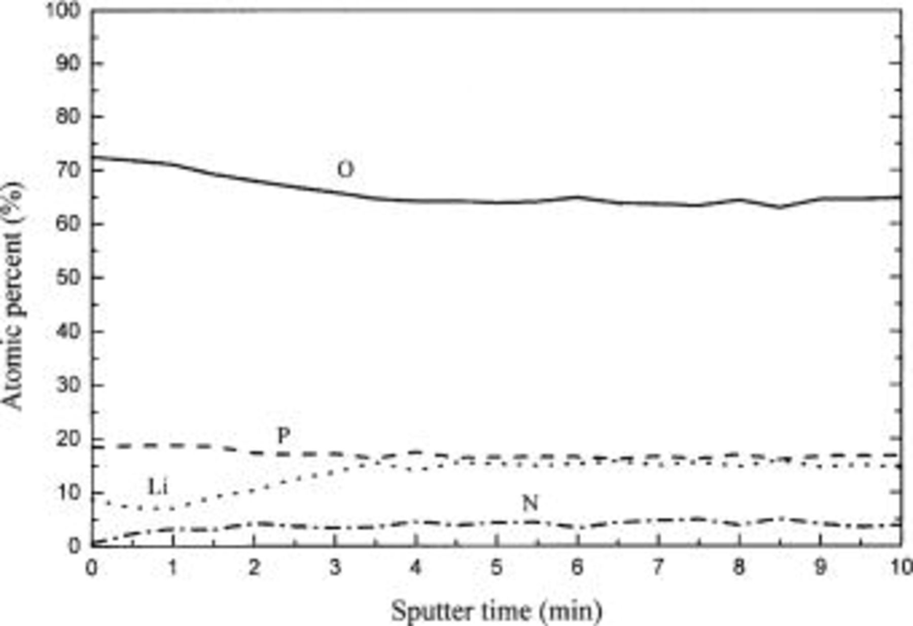
Figure 4. AES depth profile of Lipon. The contents of the film do not change with the depth of the Lipon film.
Conclusions
The ionic conductivities of Lipon films were improved by reducing the rf magnetron sputtering power, but the cycling behavior of lithium batteries may become worse because of the increase of the diffusion range. The cycling behavior of the rechargeable batteries using Lipon solid electrolyte deposited at different rf magnetron sputtering power needs further work.
The following sputtering process is suggested. First, nitrogen gas decomposes into nitrogen ions and electrons when plasma occurs. Second, some of the nitrogen ions are incorporated into  replacing some oxygen ions. Finally, nitrogen ions incorporated into
  adhere onto the substrate, and, at the same time, extracted oxygen ions and remaining nitrogen ions combine with the electrons that are produced when nitrogen gas is decomposed.
This process could be confirmed by AES depth profiling. That is, nitrogen incorporation into the Lipon films is by the reactive sputtering process not by the poisoning effect.
The Korea Institute of Science and Technology assisted in meeting the publication costs of this article.