Abstract
The characterization of new type of alkaline fuel cell based on oxidation of chemical hydride has been studied. The chemical hydride can be used as a new fuel source in a fuel cell system. As a result, we have discovered that the electrochemical reaction rate is higher at a normal temperature compared with cells containing other hydrogen fuels where a hydrogen-releasing agent,  is added to an aqueous alkaline solution of electrolyte as hydrogen fuel. That is, the fuel can be supplied very simply for the cell. If air is supplied to the oxygen cathode made of highly dispersed platinum particles supported in high-surface-area carbon paper, and the hydrogen releasing agent is fed to the alkaline solution of electrolyte at the side of metal hydride anode
  alloy), the cell can produce electric current continuously. Also it can be operated at a normal temperature and produce a large amount of energy due to its high energy density of 6,000 Ah/kg or more (for
  or
or  Therefore, the developed cell has higher electrochemical reaction rate and energy density than the conventional fuel cells using other hydrogen sources. © 2002 The Electrochemical Society. All rights reserved.
Export citation and abstract BibTeX RIS
Fuel cells produce the electric current directly by the electrochemical reaction of hydrogen with atmospheric oxygen.1 2 3 Generally, fuel cells whose anode is directly supplied with hydrogen gas as a fuel have been utilized because the electrochemical reaction can also occur at a normal temperature and its efficiency is very high. However, hydrogen fuels have the disadvantage that their storage density is lower than that of other fuels, and thus, their economical efficiency is low.
In the meantime, studies of fuel cells of the type which employ a hydrogen-containing hydrocarbon compound such as methane, propane, methanol, hydrazine, ammonia, and the like in place of the hydrogen gas in the solution of electrolyte, or of the type which supplies hydrogen reformed from such a compound for the anode, have been developed.4 5 6 7 However, these fuel cells have the disadvantage that they require high temperature (e.g., 100-300°C) for effective oxidation/reduction reactions of hydrogen/oxygen and that the reaction rate is slower. Thus, the reaction efficiency is degraded as compared with cells using hydrogen gas.
As a new fueling concept, it can be suggested that the chemical hydrides act as new fuel media supplying hydrogen at normal temperature. Chemical hydrides ( LiH, NaH, etc.) are very reactive with water, which results in releasing a large amount of
  Generally, to minimize the hydrolysis, the borohydride ion should be stabilized by hydroxide ions
  which is confirmed by the empirical rule.8 The solution can release hydrogen gas if catalyzed or acidified. Therefore, in battery applications, gas-releasing conditions are to be avoided. Release of hydrogen gas is undesirable because it can reduce the energy available and cause a variety of other undesirable characteristics for the cell. The chemical hydride (reducing agent) plays a role in reducing a metal hydride in alkaline solution through producing the hydrogen atom in the oxidation/reduction reaction.
As a representative example, Iwakura et al. have suggested that  acts as a reducing agent for improving the activation properties of a metal hydride (MH) electrode.9
They have also found that the lattice volume of alloy was expanded due to the absorption of hydrogen atoms released from  into the alloy particles and the formation of the new electroactive surfaces. It has been suggested that a key factor in modification by a reducing agent for improving the characteristics of MH electrodes is due to both the electrons and atomic hydrogen released.
Wakao et al. have also investigated the behavior of Zr-based hydrogen storage material in the alkaline solution containing the reducing agent such as hydrazine  10 When these alloys were immersed in the hydrazine solution, they rapidly extracted and absorbed hydrogen from hydrazine molecule until they were saturated by hydrogen. As a result of the extraction of hydrogen, the evolution of nitrogen gas occurred. Immersing hydrogen-absorbing alloys into the hydrazine solution is one of the interesting techniques of hydriding. Eventually, as a similar concept, knowing MH electrode characteristics of the cell reaction in borohydride solution is important to its application to the electrode of a borohydride fuel cell.
In this work, we have extensively studied approaches for overcoming these disadvantages of conventional fuel cells using other hydrogen sources. As a result, we have discovered that when a hydrogen-releasing agent,  is added to an aqueous alkaline solution of electrolyte as hydrogen fuel, the electrochemical reaction rate is higher at a normal temperature than that of cells containing other hydrogen fuels.
Theoretical Background
According to the present work, an alkaline fuel cell is provided which contains a hydrogen-releasing agent (chemical hydride) selected from the group consisting of 

 KH, and NaH. The reactions at the electrodes of the alkaline fuel cell containing the hydrogen-releasing agent are as mentioned below.
First, the added hydrogen-releasing agent releases hydrogen and electrons in the aqueous solution of electrolyte through electrochemical decomposition and oxidation by the hydrogen storage alloy catalyst. Where the hydrogen-releasing agent is  the following reactions will occur


Equations 2 to 10 can be represented by the following single equation

Where the hydrogen-releasing agent is  or the others, similar decomposition reactions to Eq. 2-10 will occur in the aqueous solution of electrolyte to produce hydrogen in the solution.
Hydrogen, which is generated by the above hydrogen-releasing agent, is stored in a hydrogen storage alloy anode as a hydrogen storage material, e.g., metal hydrides to supply the hydrogen fuel. The reaction involved can be represented by the equation

wherein M represents a metal or an intermetallic compound (hydrogen storage alloy), and  represents a metal hydride.
Thus, the generation of hydrogen and electron in the alkaline solution containing a hydrogen-releasing agent, and the subsequent storage of the hydrogen in the hydrogen storage alloy can be represented by Eq. 13


Hydrogen, which has been stored in MH electrode, produces electrons by dehydrogenation, i.e., oxidation of the hydrogen storage alloy at the anode, as in the anode of nickel/metal hydride (Ni/MH) cell (see Eq. 14)

In addition, the reduction reaction of hydrogen released from the hydrogen-releasing agent as shown in the following (Eq. 15), and the electron-releasing reaction as in the following (Eq. 16) can occur in the alkaline solution of electrolyte


In the meantime, atmospheric oxygen fuel is supplied for the oxygen cathode to cause the reduction reaction of Eq. 17 at the interfaces between the electrode and the aqueous solution of electrolyte, and thus, electrons are consumed


Thus, where the hydrogen-releasing agent is either  or
or  the overall reaction of an atmosphere/hydrogen storage alloy cell containing the hydrogen-releasing agent can produce electric energy by the following three electrochemical oxidation/reduction reactions


The key half-reaction which defines the fuel side (anode; negative electrode) of the cell is based on borohydride ions. Equation 18 is written for an aqueous system but is not limited to such a system. The new type of fuel cell uses air electrode to provide the other half-cell reaction (Eq. 17) required to make a complete cell. The theoretical voltage for net reaction of the cell is 1.64 V.
Experimental
An aqueous solution containing 1 g of  in 500
  of 6 M KOH was used. A
  alloy was used as an anode. The hydrogen storage alloy electrode was prepared by melting the weighed amount of each pure metal under an argon atmosphere, mechanically pulverizing, and then mixing with an appropriate amount of copper or nickel powder and Teflon powder. The resulting mixture was pressure molded. The hydrogen storage alloy electrode was made in disk form, and has a size of 1 cm in diam and 1 mm in thickness. The weight of the disk alloy electrode was 0.24 g. A platinum-dispersed carbon electrode (Pt/C) was used as a cathode. The Pt/C electrode was made by dispersing 5% by weight of platinum in Vulcan XC-72 (purchased from E-TEK; a carbon black). The hydrophobic/hydrophilic treatment was carried out as follows. The Pt/C powder and polytetrafluoroethylene (PTFE) were mixed in weight ratios of 70/30 for the hydrophilic side of the electrode, and 60/40 for the hydrophobic of the electrode. The mixed powders were intimately mixed in distilled water by ultrasonic agitation, and rolled in a carbon paper. The rolled powder was covered by a carbon paper which was made by dispersing and coating 20% by weight of platinum in Vulcan XC-72 (purchased from E-TEK) at a laboratory, and the moisture was removed by pressing, followed by drying at 120°C in a nitrogen atmosphere. The reaction layer was attached with the carbon paper by pressing and calcining at the melting point of PTFE, i.e., 300°C for 1 h to obtain a specimen. The final pressure had a diam of 15 mm and a thickness of 0.2 mm. In order to increase the ionic conductivity of electrolyte 2, for example, LiOH may be added to the alkaline solution of electrolyte in an amount of 0.01 to 0.1% by weight.
Results and Discussion
The developed fuel cell is further illustrated with reference to Fig. 1. The electrolyte which can be employed in this work is an alkaline electrolyte at  for example, KOH, NaOH, etc.
  containing solution is stabilized in alkaline one, retarding the evolution rate of hydrogen gas. A hydrogen-releasing agent was selected from the group consisting of

 KH, and NaH. The
  has the highest specific hydrogen storage capacity of all hydrogen-releasing agents. The hydrogen-releasing agent should be used in an amount of 0.01 to 50.00% by weight on the basis of the total weight of the alkaline solution of electrolyte. When the amount of hydrogen-releasing agent used is less than the lower limit of the range, the amount of hydrogen to be released will be lowered. This degrades the efficiency of the cell. When the amount of hydrogen-releasing agent used is more than the upper limit of range, the hydrogen-releasing agent is not dissolved in the alkaline solution, resulting in the formation of solid precipitates. This also degrades its utility and efficiency. Oxygen electrodes are made of materials which oxygen can be easily engaged in an oxidation/reduction reaction on its surface. For example, such electrodes may include carbon electrodes, platinum-dispersed carbon electrodes, nickel electrodes, and the like which have a double or triple structure consisting of a hydrophilic side interfaced with electrolyte and a hydrophobic side interfaced with atmosphere. The preferable hydrogen storage alloy is one which can reversibly absorb and release hydrogen irrespective of the hydrogen storage capacity. It should reveal the properties of a fast hydrogenation reaction rate, and a good stability in the electrolyte. The aqueous electrolyte solution provides an electrode/electrolyte interface by means of capillary action through the separator. It also acts as an ion conductor between the electrodes. It was observed by an X-ray diffraction (XRD) analysis that upon exposing the hydrogen storage alloy anode to the solution of electrolyte containing the hydrogen-releasing agent without ant external treatment, the reaction at the alloy electrode caused a change from an intermetallic compound to a metal hydride by the action of the hydrogen-releasing agent added. It can be seen from Fig. 2a, b that the hydrogen fuel could be supplied to the hydrogen storage alloy electrode without any treatment.
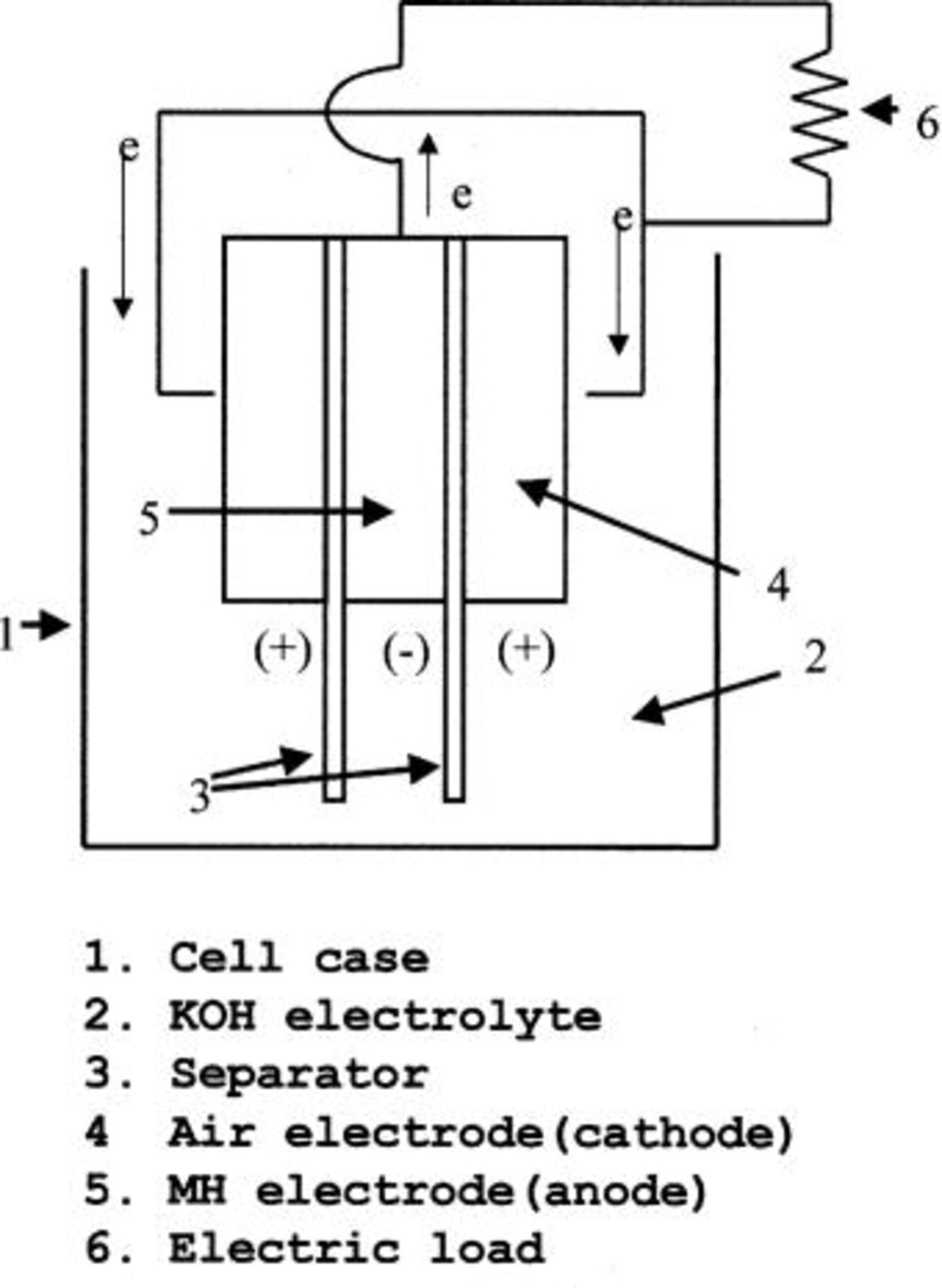
Figure 1. A schematic structure of developed fuel cell.
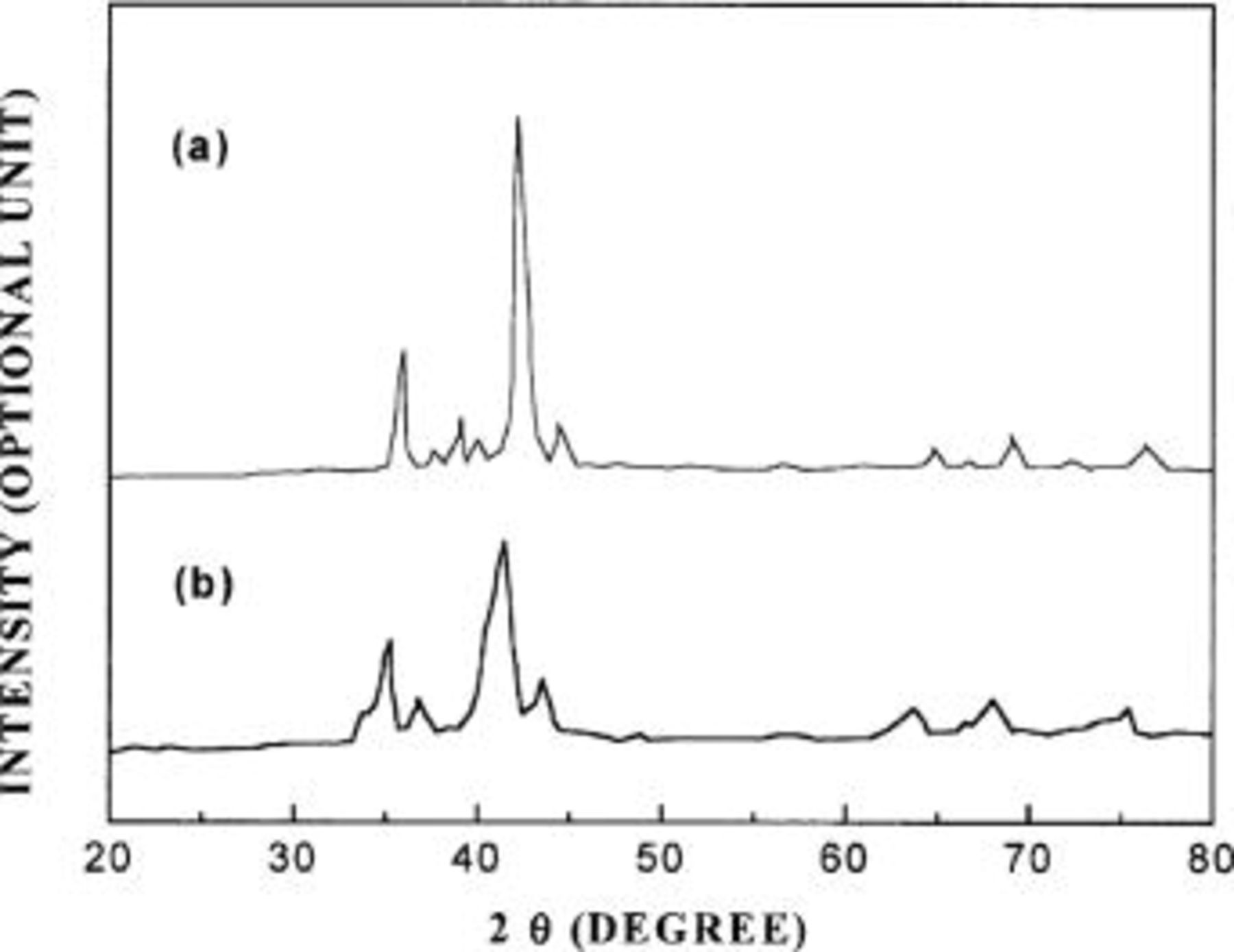
Figure 2. (a) An XRD pattern of a pressure-molded hydrogen storage alloy electrode, which is not exposed to the alkaline solution of electrolyte. (b) An XRD pattern of a pressure-molded hydrogen storage alloy electrode of Fig. 2a after the electrode is impregnated in the alkaline solution of electrolyte.
After the hydrogen storage alloy absorbed hydrogen, the cell was discharged at 10 mA with measuring of its discharge voltage. The results are indicated by a discharge curve in Fig. 3. It can be seen that the discharge voltage is about 0.7 V and that the overpotential of about 0.3 V is generated. Such overpotential is mostly generated from the oxygen cathode. However, if pure oxygen gas, not air, is supplied to the oxygen cathode and the volume of oxygen to be supplied is increased, the overpotential decreases as shown in Table I. A glass tube for gas feeding was inserted into the rear side of the oxygen electrode, and the tube was connected with the pressurized oxygen cylinder. The flow rate of oxygen (or air) was controlled by a valve or a ventilator. Table I shows the discharge voltage of the cell depending on the flow rate of either oxygen gas or air.
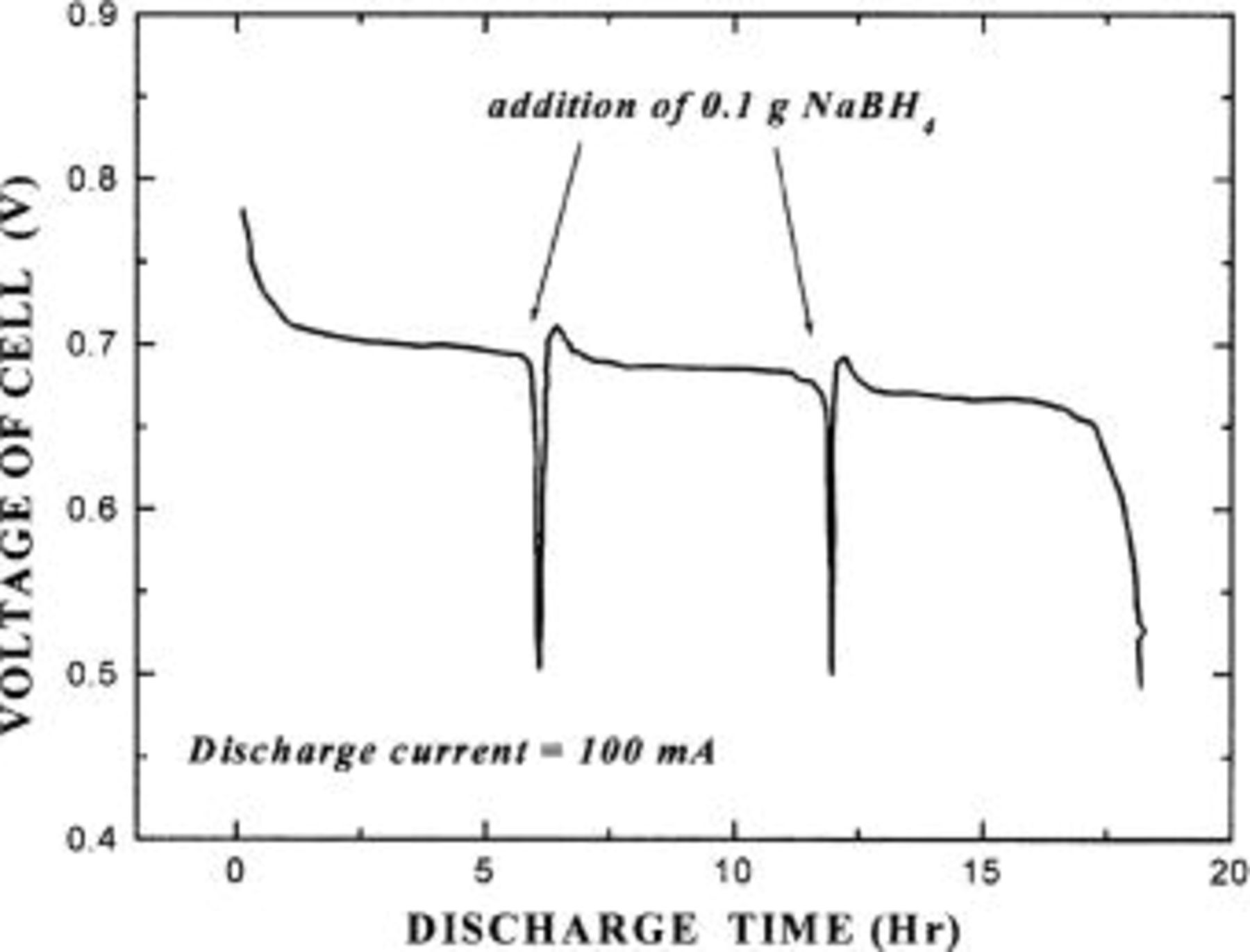
Figure 3. A current discharge curve of a fuel cell containing a hydrogen-releasing agent.
Table I.
| Discharge voltage of the cell depending on the flow rate of either oxygen gas or air. | |||
|---|---|---|---|
| Flow rate of air(L/min) | Dischargevoltage(V) | Flow rate of oxygen(L/min) | Dischargevoltage (V) |
| 0 | 0.71 | 0 | 0.8 |
| 0.1 | 0.73 | 0.1 | 0.84 |
| 0.2 | 0.78 | 0.2 | 0.88 |
| 0.5 | 0.85 | 0.5 | 0.95 |
Consequently, the developed cell has a higher electrochemical reaction rate than those of the conventional fuel cells using other hydrogen sources. It can operate at a normal temperature and produce a large amount of energy due to its high energy density of 6,000 Ah/kg or more (for  or
or  ).
).
Whenever the discharge voltage of the cell decreased to below 0.5 V, 1 g of  as a hydrogen fuel source was supplied for the solution electrolyte, the continuous generation of current was monitored continuously. It can be shown in Fig. 4 that the fuel cell continuously generates current when the hydrogen-releasing agent is added to the electrolyte solution. That is, the fuel cell (electrochemical oxidation/reduction reaction) continuously operates as long as oxygen and hydrogen fuel are supplied.
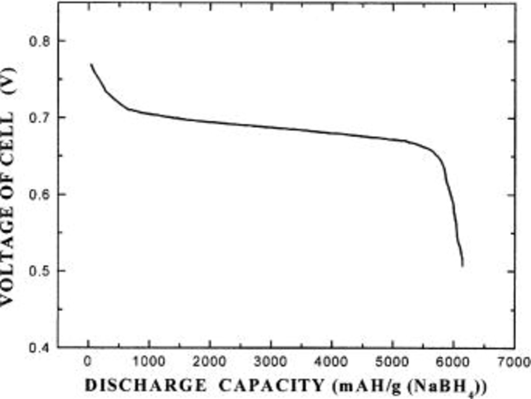
Figure 4. A current discharge curve of a fuel cell, where the hydrogen-releasing agent is intermittently added to the fuel cell.
Conclusion
The present work has been described to provide a fuel cell having a high electrochemical reaction efficiency and a good discharge capacity, which comprises an aqueous alkaline solution of electrolyte containing a hydrogen-releasing agent selected from the group consisting of 

 KH, and NaH, a hydrogen storage alloy electrode as an anode, and an oxygen electrode as a cathode.
If air is supplied to the oxygen electrode and the hydrogen-releasing agent is fed to the alkaline solution of electrolyte, the cell can produce electric current continuously. Therefore, it can operate at a normal temperature and produce a large amount of energy due to its high energy density of 6,000 Ah/kg or more (for  or
or  ).
).
The Korea Advanced Institute of Science and Technology assisted in meeting the publication costs of this article.