Abstract
The formula describing the energy density of asymmetric cells, which consists of a battery-type electrode (such as lithium intercalated compound) and an electrochemical capacitor-type electrode (such as activated carbon), was derived. From the formula, the optimal mass (or volume) ratio of battery electrode to capacitor electrodes and electrolyte can be obtained for achieving the maximum theoretical gravimetric (or volumetric) energy density. The voltage swing of the cell during charge and discharge cycles was also described. Relationships between the energy density, ion concentration of the electrolyte, specific capacity of battery electrode, specific capacitance of capacitor electrode, and maximum operational voltage were also given. Three specific asymmetric systems, including carbon/ ethylene carbonate:dimethyl carbonate
  carbon/
 and
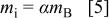
and 
 /carbon were evaluated for their maximum theoretical energy density and swing voltage. It was found that for asymmetric cells using nonaqueous electrolyte, the maximum energy density (about 30 Wh/kg) was limited mainly by the electrolyte due to the low ion concentration; however, for asymmetric cells using aqueous electrolytes, the maximum energy density (about 40 Wh/kg) was limited mainly by the capacitor electrode. The maximum operational voltage always plays an important role in the maximum energy density. © 2003 The Electrochemical Society. All rights reserved.
Export citation and abstract BibTeX RIS
The energy density of electrochemical capacitors is still less than 10% of that of advanced batteries.1
2 The low energy density of electrochemical capacitors is mainly due to the following reasons: (i) The charge is stored only at the electrode surface [such as double-layer (dl) on carbon and pseudocapacitance on  . The charge density in these materials is very low compared to that due to the large ion intercalation (such as graphite,
  in lithium-ion batteries) or chemical reaction (such as NiOOH in Ni-Cd batteries).3
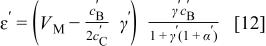
4 (ii) The potentials of both electrodes in electrochemical capacitors swing between low and high potential during charge and discharge cycles. Unlike batteries, the potentials of both negative and positive electrodes are pinned at low and high potentials, respectively. (iii) For dl capacitors, ions in electrolyte are consumed during charge;5
6 therefore, the energy density of the capacitor is dependent not only on the specific capacitance of the electrode material and the stable potential window, but also on the ion concentration of the electrolyte. For capacitors that use nonaqueous electrolytes, the limitation of the maximum energy density is due mainly to the low ion concentration of the electrolyte.5
in lithium-ion batteries) or chemical reaction (such as NiOOH in Ni-Cd batteries).3
4 (ii) The potentials of both electrodes in electrochemical capacitors swing between low and high potential during charge and discharge cycles. Unlike batteries, the potentials of both negative and positive electrodes are pinned at low and high potentials, respectively. (iii) For dl capacitors, ions in electrolyte are consumed during charge;5
6 therefore, the energy density of the capacitor is dependent not only on the specific capacitance of the electrode material and the stable potential window, but also on the ion concentration of the electrolyte. For capacitors that use nonaqueous electrolytes, the limitation of the maximum energy density is due mainly to the low ion concentration of the electrolyte.5
In order to increase the energy density and at the same time maintain the extended cycle life and fast charge capability, asymmetric cells consisting of a dl electrode and a battery electrode [such as lithium intercalation component or  were introduced.7
8
9
10
11
12 The battery electrode is selected such that the potential is either near the low or high end of the potential window, which can maximize the operational voltage as well as the energy density of the cell. For the battery electrode, nanosized materials were used for improvement in lithiation rate capability. For nonaqueous electrolyte cells, nanostructural
were introduced.7
8
9
10
11
12 The battery electrode is selected such that the potential is either near the low or high end of the potential window, which can maximize the operational voltage as well as the energy density of the cell. For the battery electrode, nanosized materials were used for improvement in lithiation rate capability. For nonaqueous electrolyte cells, nanostructural  and
and  were used as negative electrodes7
8 operated at potentials of −1.2 and −2.5 V vs. Ag, respectively, and activated carbon was used as the positive electrode. The maximum operational voltages of about 3.2 and 3.6 V, respectively, were achieved in cells using
were used as negative electrodes7
8 operated at potentials of −1.2 and −2.5 V vs. Ag, respectively, and activated carbon was used as the positive electrode. The maximum operational voltages of about 3.2 and 3.6 V, respectively, were achieved in cells using  ethylene carbonate:dimethyl carbonate (EC:DMC) electrolyte. An asymmetric cell with aqueous electrolyte utilized the high conductivity of the electrolyte in order to improve the power performance of the cell. In the cell, activated carbon (AC) and nanosized
  were used as negative9
10 and positive electrode materials, respectively. In another approach, AC and conducting polymer12 were used an asymmetric cell as negative and positive electrode materials, respectively. In these type cells, the potentials of both electrode swing during charge and discharge cycles; however, the amplitude of the swing potential of the conducting polymer electrode was smaller than that of the carbon electrode. The maximum operational voltage of 3 V was obtained.
were used as negative9
10 and positive electrode materials, respectively. In another approach, AC and conducting polymer12 were used an asymmetric cell as negative and positive electrode materials, respectively. In these type cells, the potentials of both electrode swing during charge and discharge cycles; however, the amplitude of the swing potential of the conducting polymer electrode was smaller than that of the carbon electrode. The maximum operational voltage of 3 V was obtained.
In this paper, a model was developed for calculation of the energy density and swing voltage in asymmetric cells to yield electrochemical and physical properties of electrode materials and electrolyte. With the model, the maximum energy density and the optimized mass or volume ratio of two electrodes can be obtained. The strong influence of electrolyte on the energy density of the cell is discussed.
Gravimetric Energy Density
Figure 1 shows schematic potential changes of two electrodes during the charge process for a asymmetric cell (e.g., carbon as the positive electrode and battery electrode as the negative electrode). During the charge process, a nonfaradaic reaction at the AC positive electrode causes a linear increase in potential as total charge increases; while a faradaic intercalation at the negative electrode occurs at a constant potential. The charge accumulated at the surface of carbon is proportional to the voltage swing range and can be expressed as
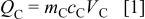
where  and
and  are the mass and specific capacitance
  of the positive electrode material, and
  is the voltage swing during charge. The maximum charge stored at the surface of carbon is determined by the maximum operational voltage
  On the other hand, the maximum charge stored at the negative electrode is
where  and
and  are the mass and specific capacity (Ah/g) of the negative electrode material, respectively. For a asymmetric cell, charges at both electrodes should be balanced and also equals the charge of ions consumed from the electrolyte. The maximum charge from ions available in the electrolyte can be expressed as5
where  and
and  are the mass and ion concentration of the electrolyte, ρ is the mass density of the electrolyte, and
  is Faraday's constant. During the charge process, the change in charges on positive and negative electrodes, and electrolyte, are the same. The maximum charge that can be stored in the asymmetric cell will be determined by the smallest value in amount of
 and
and  First, assume that the maximum charge stored in the cell is limited by the negative electrode, which can be described as
  The total energy stored in asymmetric cell can be calculated as
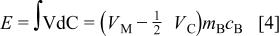
which is the area of the quadrilateral in Fig. 1 with length of capacity  and height of voltage (e.g., average voltage
  . The energy density of the cell will be the total energy divided by the sum of total masses including both electrodes and electrolyte. However, the minimum mass of required electrolyte can be obtained from the charge balance relationship of
  and is
where  is the minimum value of mass ratio of the electrolyte to negative electrode required to utilize the entire capacity of the negative electrode. After combining Eq. 2 to 5, the energy density of the asymmetric cell can be expressed as
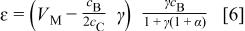
where  is the mass ratio of the two electrodes. It can be proved that
  is always less than zero, which indicates that only one maximum value of ɛ can be obtained. The maximum energy density
  can be obtained at the electrode mass ratio of
  at which
  Therefore, it can be proved that the maximum energy density can be obtained at the mass density of
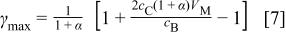
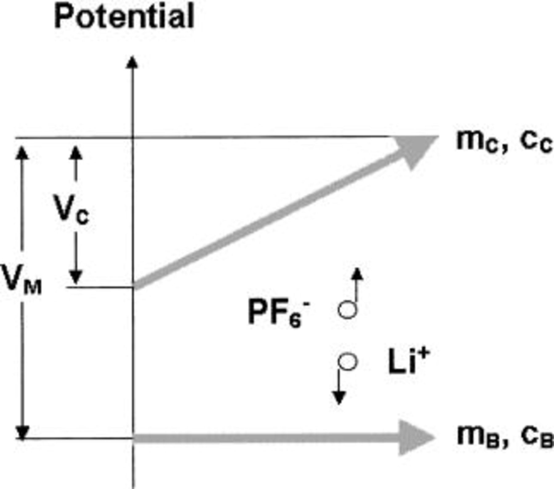
Figure 1. Schematic potential changes of dl and intercalation electrodes during the charge process.
The swing voltage can also be obtained from the charge balance relationship of  and can be expressed as
It can be seen that both energy density and swing voltage of the asymmetric cell depend on the mass ratio of two electrodes.
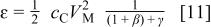
When the maximum charge in the cell is limited by the positive electrode,  The swing voltage will be
  and the total energy stored in asymmetric cell can be expressed as
The minimum mass of electrolyte can be obtained from the charge balance relationship of  and is
where  is the minimum value of mass ratio of the electrolyte to positive electrode that enable utilization of the whole capacity of the positive electrode. The energy density can be expressed as
Eq. 11 shows that the energy density decreases monotonously with increasing the mass ratio of electrodes. It can be proven that the energy density expressed in Eq. 6 will be the same as in Eq. 11, when the maximum capacity of the positive electrode  equals the capacity of negative electrode
Volumetric Energy Density
In a similar manner in which the gravimetric energy density is described above, the volumetric energy density can also be derived. If we define  and
and  to be volumetric specific capacitance (e.g., F/cm3) of the positive electrode and volumetric specific capacity (e.g., mAh/cm3) of the negative electrode, respectively;
 and
and  are the volumes of the positive electrode, negative electrode, and electrolyte, respectively; then very similar expressions in volumetric energy density can be obtained. When the maximum charge in the cell is limited by the negative electrode
  the volumetric energy density can be expressed as
where  is the volume ratio of two electrodes,
  is the minimum value of volume ratio of the electrolyte to negative electrode to be able to utilize the entire capacity of the negative electrode. Note that the volume of electrode is the space that it only occupies with active materials not including pore volume. In practical devices, the pore volume will be filled with the liquid electrolyte. The swing voltage can be expressed as
The maximum volumetric energy density can be obtained from Eq. 12 at a volume ratio of electrodes at
When the maximum charge in the cell is limited by the positive electrode  the volumetric energy density can be expressed
where  is the minimum value of volume ratio of the electrolyte to positive electrode to enable utilization of the entire capacity of the positive electrode. The swing voltage will be a constant value of
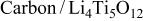
Carbon- Cell
Cell

An asymmetric cell with AC positive electrode,  negative electrode, and
  EC:DMC electrolyte was introduced by Amatucci and co-workers.7
8 The energy density of 25 Wh/kg was measured for a 400 mAh plastic cell at the maximum operational voltage of 3.2 V. The swing voltage was about 1.3 V at C/2 charge rate. Figure 2 shows the theoretical energy density and the voltage swing of the cell as a function of mass ratio of electrodes calculated by the derived equations. From calculations, the specific capacitance13 for the AC positive electrode was
EC:DMC electrolyte was introduced by Amatucci and co-workers.7
8 The energy density of 25 Wh/kg was measured for a 400 mAh plastic cell at the maximum operational voltage of 3.2 V. The swing voltage was about 1.3 V at C/2 charge rate. Figure 2 shows the theoretical energy density and the voltage swing of the cell as a function of mass ratio of electrodes calculated by the derived equations. From calculations, the specific capacitance13 for the AC positive electrode was  the specific capacity7 for the
  negative electrode was
  and ion concentration of
  for
for  EC:DMC electrolyte; a maximum operating voltage of
  were used. It can be seen that the energy density increases with increasing the mass ratio of two electrodes
  and reaches the maximum value of 32.7 Wh/kg at a mass ratio of
  From values of
  and α, it can be determined that at the maximum energy density, the mass distribution in the cell is
  From Fig. 2b, it can be seen that the value of swing voltage increases with increasing the mass ratio of two electrodes. At
  the swing voltage is about 1.53 V, and when
  the voltage swing is a constant value of 3.2 V and the energy stored in the cell is limited by the positive electrode. Since the swing voltage of 1.3 V is less than the theoretical value obtained at the maximum energy density, it can be easily concluded that the asymmetric cell reported by Amatucci et al. had a mass ratio of γ larger than the
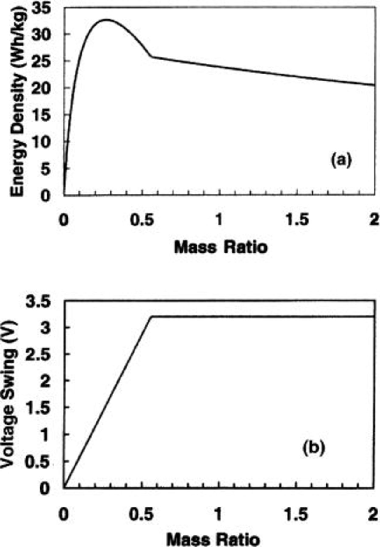
Figure 2. The (a) energy density and (b) swing voltage as a function of electrode mass ratio  for an
 cell.
cell.
Carbon- Cell

Other asymmetric cells utilize low potential intercalation  An output voltage of 3.6 V from an activated carbon/
 cell was demonstrated. Figure 3 shows the energy density and swing voltage as a function of mass ratio of the two electrodes. The volumetric specific capacity14 of 480 mAh/cm3 and mass density15 of 12.11 g/cm3 for the
  negative electrode were used during the calculation. It can be seen that the maximum energy density of 30.4 Wh/kg can be obtained at the mass ratio of
  at which the swing voltage is 1.5 V, and the mass distribution in the cell is
  It can also be seen that at
  the swing voltage is a constant value of 3.6 V and the maximum energy stored in the cell is limited by the positive carbon electrode. Compared with previous cells, the specific capacity of
  (39.64 mAh/g) is much lower than that of
  however, the maximum energy densities of asymmetric cells using
  or
or  negative electrode are almost the same. It can be understood by the fact that for an asymmetric cell using a high specific capacity electrode, the majority of the cell mass is contributed by the electrolyte. In other words, the maximum energy density is limited by the ion concentration of the electrolyte.
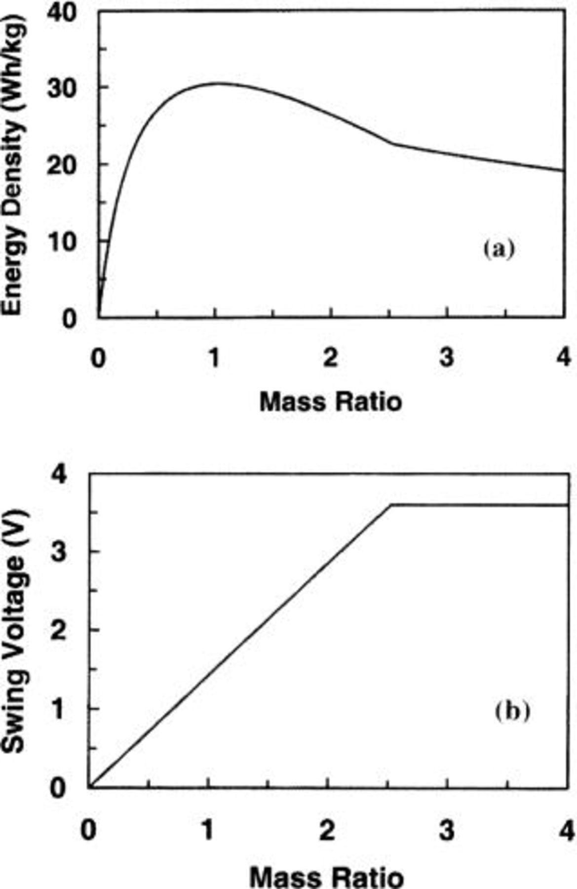
Figure 3. The (a) energy density and (b) swing voltage as a function of electrode mass ratio for an 
 cell.
cell.
Volumetric energy density and swing voltage as a function of volume ratio of the two electrodes for an 
 cell are shown in Fig. 4, in which the volumetric specific capacitance of the AC electrode is
  (because the mass density of the bulk carbon is 2 g/cm3). The maximum volumetric energy density of 55.5 Wh/L can be obtained at a volume distribution of
  (at
(at  . At the maximum volumetric energy density, the swing voltage of the cell is 0.91 V.

Figure 4. The (a) volumetric energy density and (b) swing voltage as a function of electrode volume ratio  for an
 cell.
cell.
-Carbon Cell

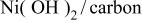
The asymmetric cell using aqueous electrolyte such as KOH solution was also reported.9 In cells, the  was used as the positive electrode and AC fiber was used as the negative electrode. The KOH solution has not only a high ionic conductivity (1/Ω cm), but also a high ion concentration (>6.25 M/L). The disadvantage of using aqueous electrolytes is that the maximum operational voltage of the cell is lower than those using nonaqueous electrolytes. Figure 5 shows the energy density and swing voltage as a function of mass ratio of the two electrodes. From calculations, the specific capacity3 for
  is 292 mA/g, the specific capacitance9 for AC is 200 F/g, a maximum operational voltage9
10 of 1.65 V, and the mass density of 1.3 g/cm3 for electrolyte were used. It was found that the maximum energy density of 41.7 Wh/kg and swing voltage of 1.225 V can be obtained at a mass ratio of
is 292 mA/g, the specific capacitance9 for AC is 200 F/g, a maximum operational voltage9
10 of 1.65 V, and the mass density of 1.3 g/cm3 for electrolyte were used. It was found that the maximum energy density of 41.7 Wh/kg and swing voltage of 1.225 V can be obtained at a mass ratio of  in the cell.
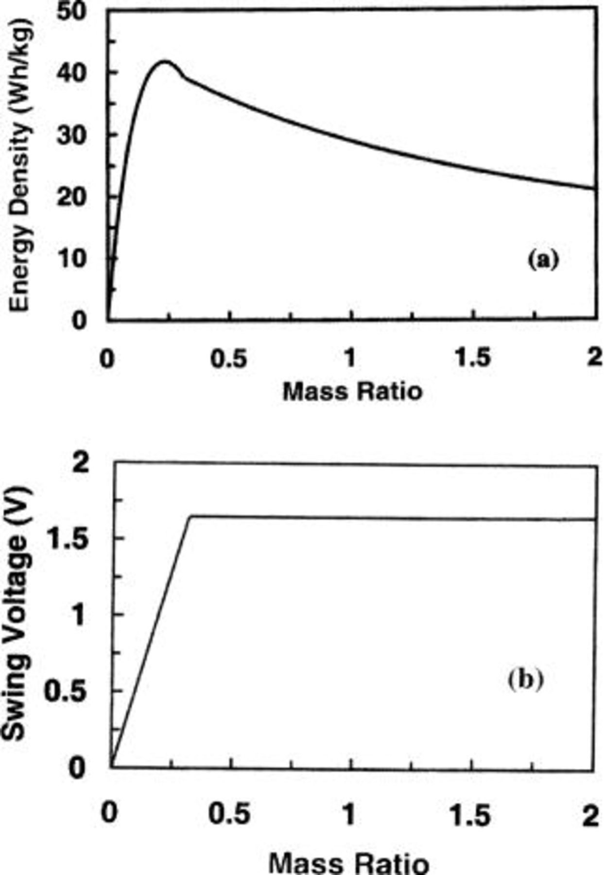
Figure 5. The (a) energy density and (b) swing voltage as a function of electrode mass ratio for a 
 cell.
cell.
Figure 6 shows the volumetric energy density and swing voltage as a function of the volume ratio of electrodes. The mass density13 of 4.15 g/cm3 and 2 g/cm3 were used for  and carbon electrodes, respectively. It is found that the maximum volumetric energy density and voltage swing of 77.7 Wh/L and 1.18 V, respectively, can be obtained at a volume ratio of
  It can be seen that at the maximum energy density, the majority of the mass (or volume) of the cell comes from the carbon electrode. Therefore, the maximum energy density of the cell for asymmetric cells using aqueous electrolytes is mainly limited by the specific capacitance of the carbon electrode.
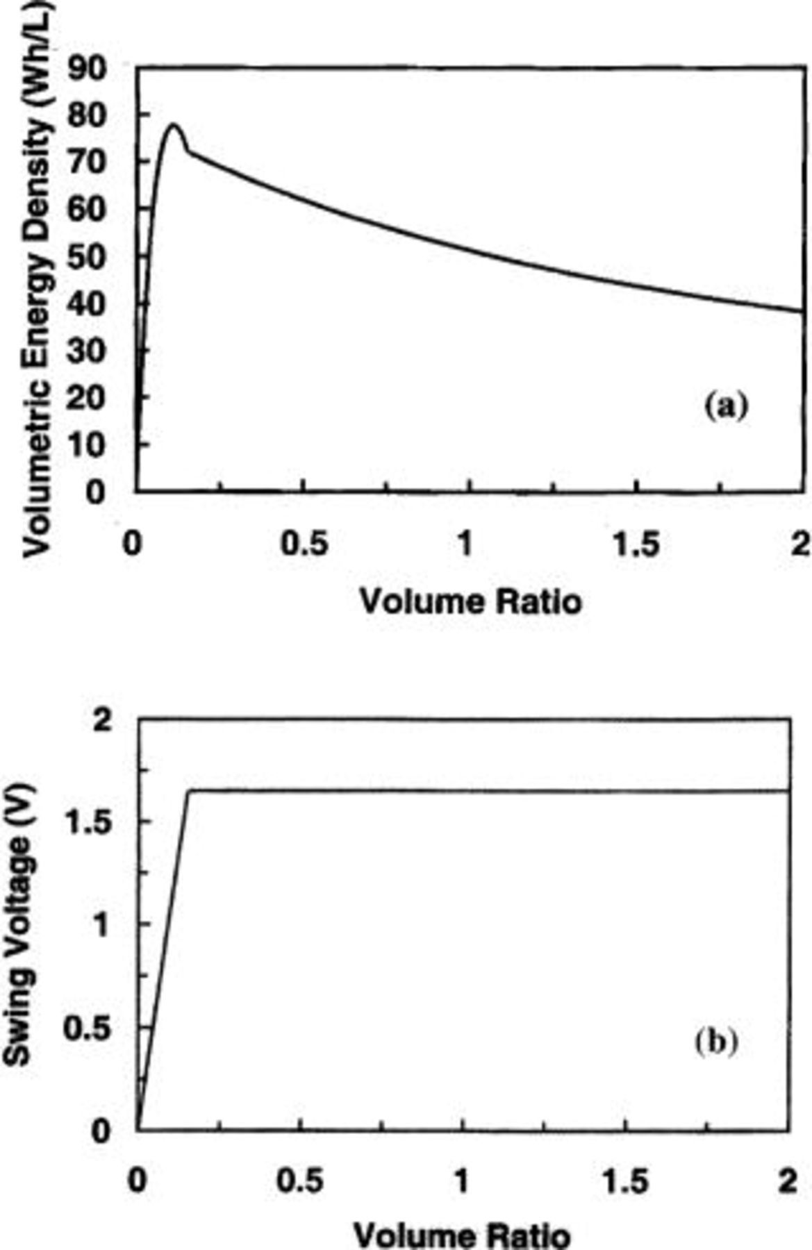
Figure 6. The (a) volumetric energy density and (b) swing voltage as a function of electrode volume ratio for a 
 cell.
cell.
A Comparison of Different Cells
Table I shows a comparison of three asymmetric cells and three electrochemical capacitors. The maximum energy densities and the mass distributions of electrochemical capacitors are calculated based on equations developed in Ref. 5. For the psedocapacitor with  electrodes, the weight of electrolyte is not included in the calculation, because the net ion exchange in electrolyte during the charge/discharge cycle does not change. Therefore, theoretically there is no minimum weight of electrolyte required in the capacitor. In Table I, the same value of specific capacitance for the activated carbon is used in both asymmetric cells and electrochemical capacitors. The advantages of asymmetric cells in the energy density and the swing voltage are evident.
Table I.
| Summary of performance of cells made with different elelctrodes and electrolytes. | ||||||
|---|---|---|---|---|---|---|
| Type of cellcathode/anode | Specific capacityor capacitance | Electrolyte | Operationalvoltage(V) | Themaximumenergydensity(Wh/kg) | Swingvoltage/operationalvoltage(%) | Massdistributioncathode/anode/electrolyte |
| Carbon/carbon | 280 F/g-280 F/g | 5.26 M/L
 in in  | 1.0 | 7.16 | 100 | 1/1/0.72 |
| Carbon/carbon | 120 F/g-120 F/g | 0.75 M/L
 in PC in PC | 3.0 | 9.41 | 100 | 1/1/5.97 |
 | 768 F/g-768 F/g | 5.26 M/L
 in in  | 1.0 | 26.7 | 100 | 1/1 |
 | 120 F/g-168 mA/g | 1 M/L  in 2 EC:DMC
 | 3.2 | 34.51 | 45 | 3.34/1/7.16 |
 | 120 F/g-40 mA/g | 1 M/L  in 2 EC:DMC
 | 3.6 | 31.73 | 38 | 0.86/1/1.77 |
 | 292 mA/g-280 F/g | 6.25 M/LKOH in  | 1.65 | 50.35 | 69 | 1/3.30/1.97 |
Ion Concentration in the Electrolyte
From the above examples, particularly, for asymmetric cells using nonaqueous electrolyte, the majority weight of the cell is contributed by the electrolyte due to the low ion concentration. Therefore, the maximum energy density of the cell is limited mainly by the ion concentration in the electrolyte. In order to further demonstrate the important role of the ion concentration in determining the maximum energy density of asymmetric cells, Fig. 7a shows the maximum energy density of the cell as a function of ion concentration of both nonaqueous and aqueous electrolytes. In the calculation, carbon- and
and  -carbon electrodes are used in cells used for nonaqueous and aqueous electrolytes, respectively. It can be seen that when the ion concentration increases, the maximum energy density increases, and at ion concentrations less than 5 M/L, the maximum energy density increases at an aggressive rate. From Fig. 7a, it can also be seen that at the same ion concentration, the maximum energy density of the cell using nonaqueous electrolytes is always greater than that using aqueous electrolytes. It is mainly due to the high operational voltage of the cell using nonaqueous electrolytes. Figure 7b shows the swing voltage of the cell as a function of ion concentration for both cells using nonaqueous and aqueous electrolytes. It can be seen that the swing voltage increases with increasing ion concentration.
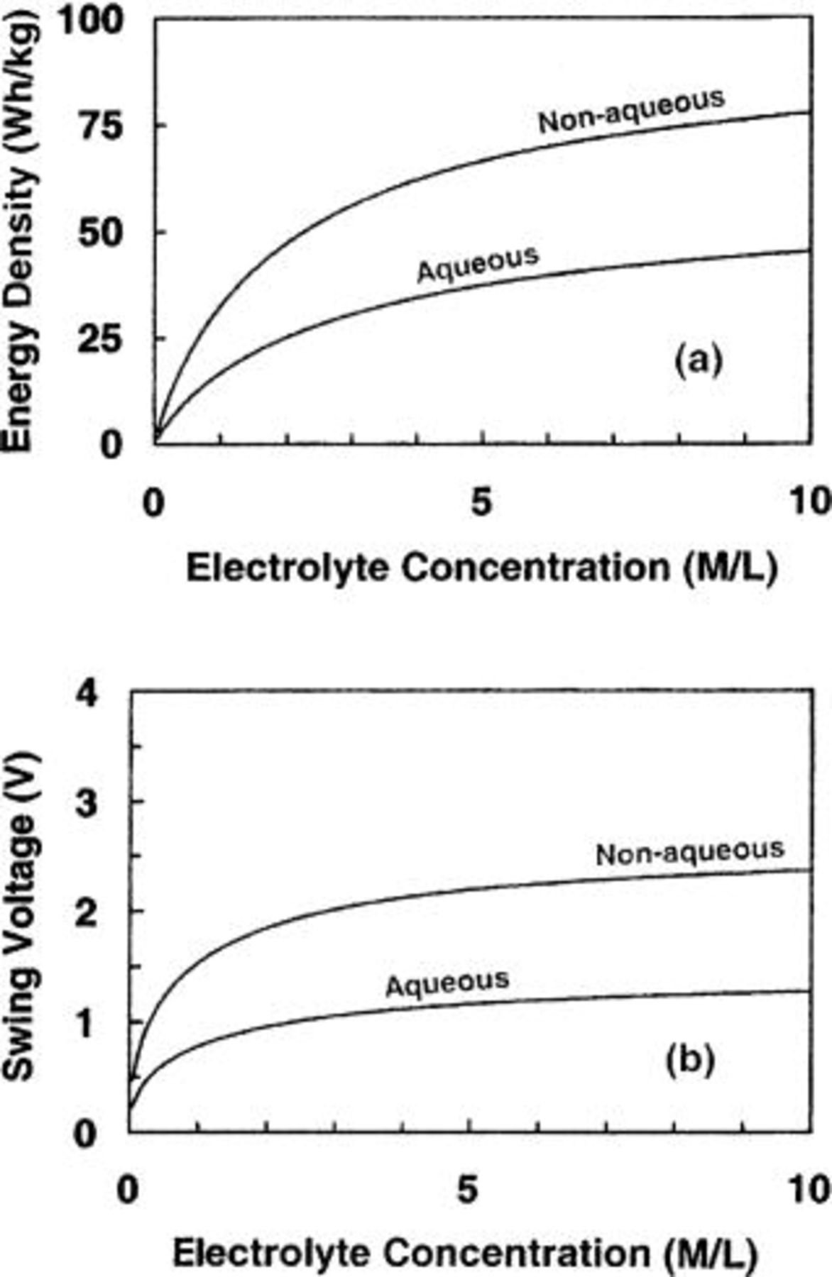
Figure 7. (a) The maximum energy density and (b) swing voltage for aqueous and nonaqueous cells as function of ion concentration of electrolyte.
It must be pointed out that for only those cells in which the salts in electrolyte will be consumed during the charge process, the ion concentration in the electrolyte will affect the energy density of asymmetric cells such as carbon/
 carbon/
 and
and 
 /carbon systems. It is not difficult to see that during the charge process, the ion concentration in the electrolyte decreases, because the
  will be intercalated into the
  or
or  anode electrode and at the same time
  will be developed near the surface of the carbon cathode electrode to establish a dl charge. Also, in cells using aqueous electrolytes,
  in the electrolyte will drift to the
  cathode to form NiOOH, and
  in the electrolyte will drift to the carbon anode to develop a dl charge at the interface of the carbon. Therefore, the salt concentration in the bulk of the electrolyte decreases during the charge process but increases during the discharge process. If the asymmetric cell is made so that during the charge and discharge cycles, ions transfer from one electrode to another electrode, with no net ion exchange between the electrode and the electrolyte such as Li ion batteries and pseudocapacitors using ruthenium oxide electrodes, then the salt concentration in the electrolyte is a constant during the entire charge and discharge cycle. In such systems, the electrolyte mainly plays the role as the ionic conductor. For this type of asymmetric cell, the energy density of the cell is dependent mainly on the specific capacity of the battery electrode, specific capacitance of capacitor electrode, and the operational voltage. The theoretical maximum energy density of the cell can still be obtained from Eq. 6 and 12 with
  However, it should be also pointed out that in practical asymmetric cells, the electrode materials for both battery and capacitor electrodes are made with porous materials. Voids in electrodes must be filled by the electrolyte in order to have a low resistance for ion transfer from one electrode to another. Therefore, the energy density of the cell will be lower than that obtained from the theoretical equations.
The energy densities described by Eq. 6 and 12 are based on the minimum required weight or volume of electrolyte in the cell. With the minimum among electrolyte, the internal resistance of the cell will be increased dramatically when the cell is charged to the voltage close to the maximum operational voltage due to ion depletion in the bulk of electrolyte. Therefore, the amount of electrolyte in practical asymmetric cells should be more than that listed in Table I, and the value of the mass or volume ratio between electrolyte and battery electrode should be greater than β and β' expressed previously.
Specific Capacity of the Battery Electrode
Figure 8a and b shows the maximum energy density and swing voltage as a function of the specific capacity of the battery electrode in asymmetric cells using electrolytes with different ion concentrations. During the calculation, the specific capacitance of the capacitor electrode is 100 F/g and the maximum operational voltage is 3.2 V. It can be seen that with increase of the specific capacity, both energy density and swing voltage increase with increasing the specific capacity; but at high value of specific capacity (e.g., >500 mA/g), they increase slowly. The energy density increase at a slow rate at high specific capacity can be easily understood from the mass ratio of  and
and  as shown in Fig. 8c and d, respectively. It can be seen that these mass ratios increase almost linearly with increasing specific capacity. At high
  the mass of
  and
and  dominate the weight of the cell.
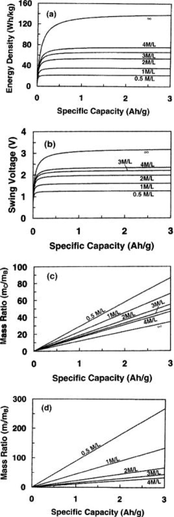
Figure 8. (a) The maximum energy density, (b) swing voltage, (c) mass ratio between capacitor electrode and battery electrode, and (d) mass ratio between electrolyte and battery electrode as a function of specific capacity of battery electrode for different concentrations of electrolyte.
Specific Capacitance of the Capacitor Electrode
Figure 9a and b shows the maximum energy density and swing voltage as a function of the specific capacitance of the capacitor electrode in asymmetric cells using electrolytes with different ion concentrations. The anode electrode is a lithium intercalation compound of  and the maximum operational voltage is 3.2 V. It can be seen that the maximum energy density of cells increases with increasing the specific capacitance of the capacitive cathode electrode. It can also been seen that the maximum energy density is increased more effectively with increasing the ion concentration of the electrolyte. For example, for a giving ion concentration of 1 M/L, when the specific capacitance increases from 100 to 200 F/g, the energy density will increase from 32.66 to 39.38 Wh/kg. However, for a given specific capacitance of 100 F/g, when the ion concentration increases from 1 to 2 M/L, the energy density will increase from 32.66 to 47.30 Wh/kg. The ion concentration of infinite value represents the situation of no net ion exchange during the charge and discharge cycles as discussed in previous section. From Fig. 9b, it can be seen that the swing voltage decreases with increasing specific capacitance, but increases with increasing ion concentration.
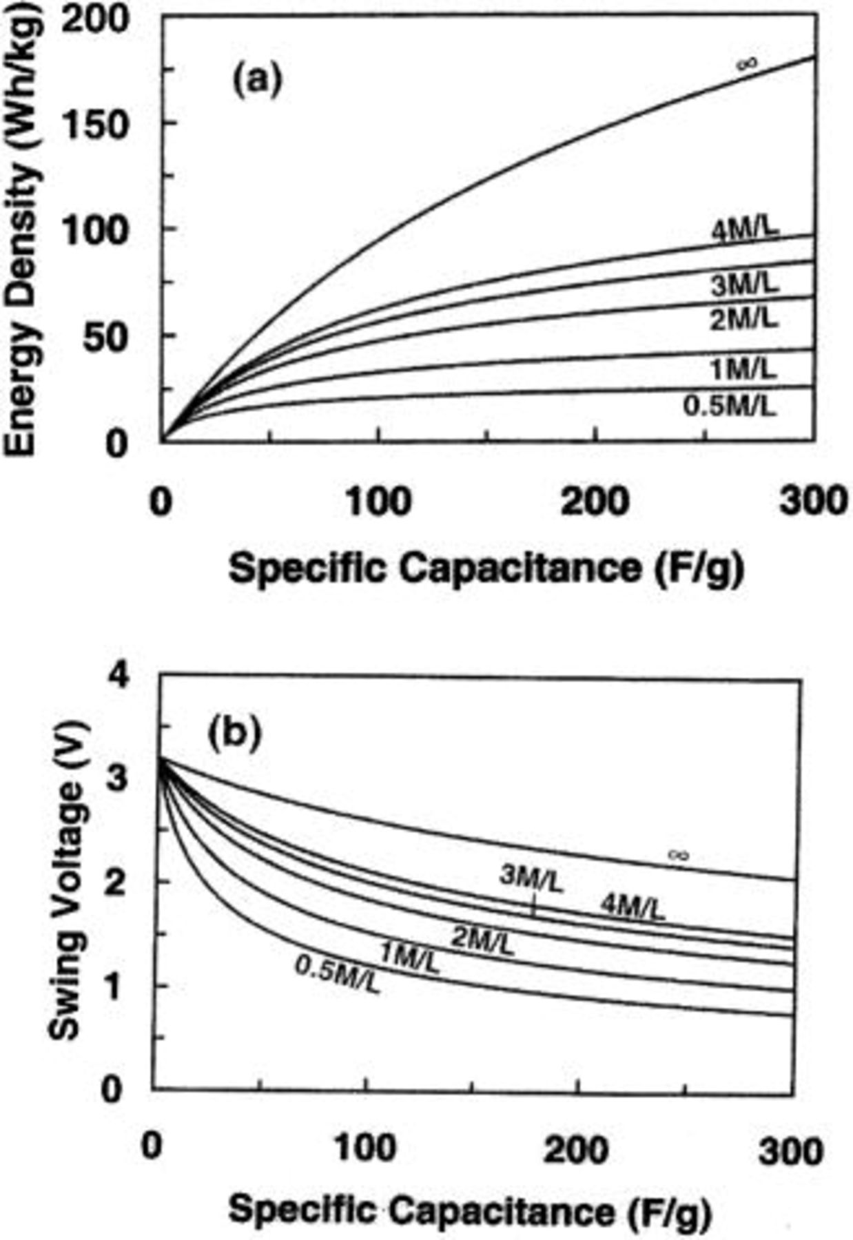
Figure 9. (a) The maximum energy density and (b) swing voltage for nonaqueous cells as function of specific capacitance of capacitor electrode.
Figure 10a and b shows the maximum energy density and swing voltage as a function of specific capacitance of the capacitor electrode in asymmetric cells with  cathode electrodes. The maximum operational voltage of the cell is 1.65 V. Ion concentration in aqueous electrolytes are high such as 5.26 and 6.25 M/L for
  and KOH, respectively, and further increase in ion concentration has very limited effect on the increase of the maximum energy density of the cell. Therefore, an effective way for increasing the energy density is to use anodes with high specific capacitance.

Figure 10. (a) The maximum energy density and (b) swing voltage for aqueous cells as function of specific capacitance of capacitor electrode.
Operational Voltage
Figure 11a and b demonstrates the maximum energy density and swing voltage as a function of the maximum operating voltage for nonaqueous cells in which the anode and cathode electrodes are a lithium intercalation compound of  and AC (100 F/g), respectively. The maximum operational voltage is 3.2 V. Figure 12a and b demonstrates the maximum energy density and swing voltage as a function of the maximum operating voltage for aqueous cells in which the anode and cathode electrodes are activated carbon (200 F/g) and
  respectively. The maximum operational voltage is 1.65 V. Figure 11a and 12a both show that the energy density increases rapidly with increasing operational voltage. However, Fig. 11b and 12b show that the swing voltages for both nonaqueous and aqueous cells increase almost linearly with increasing operational voltage.
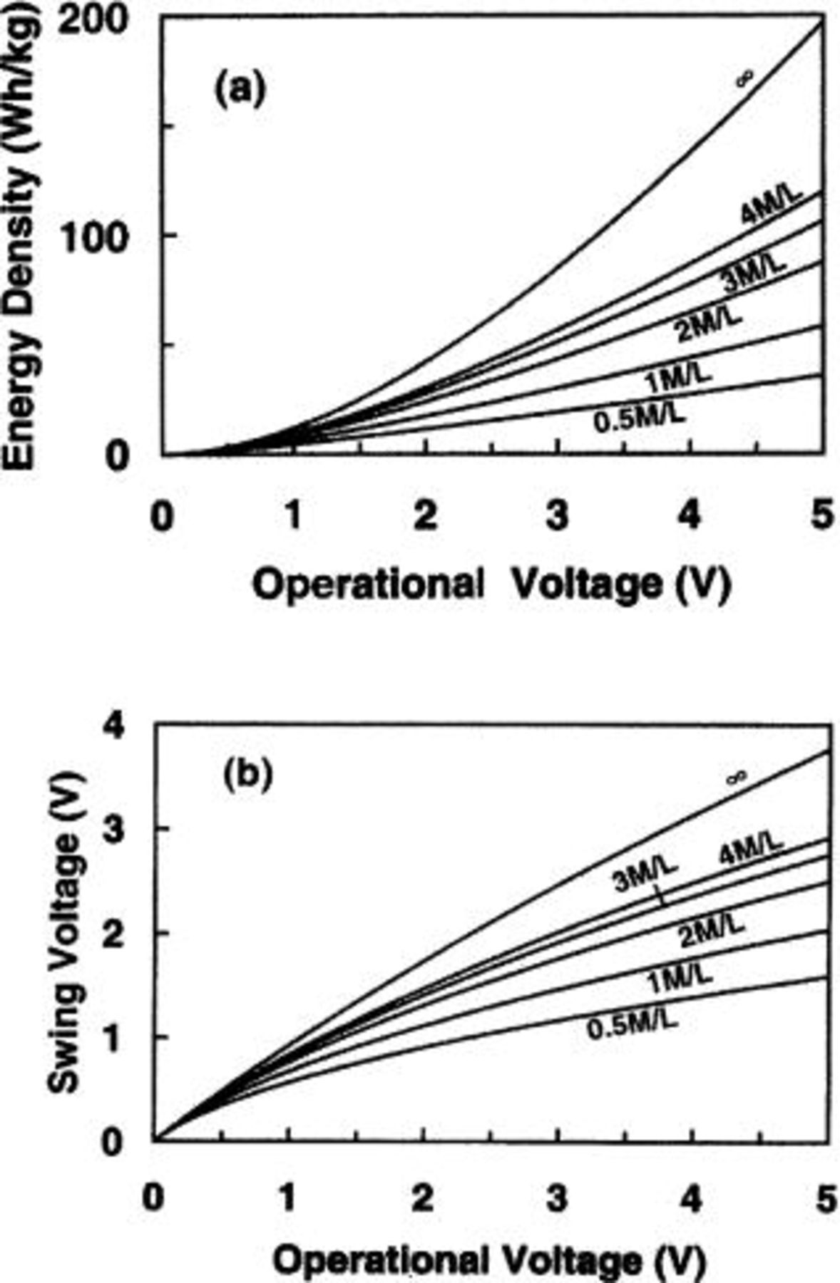
Figure 11. (a) The maximum energy density and (b) swing voltage for nonaqueous cells as function of the maximum operational voltage.
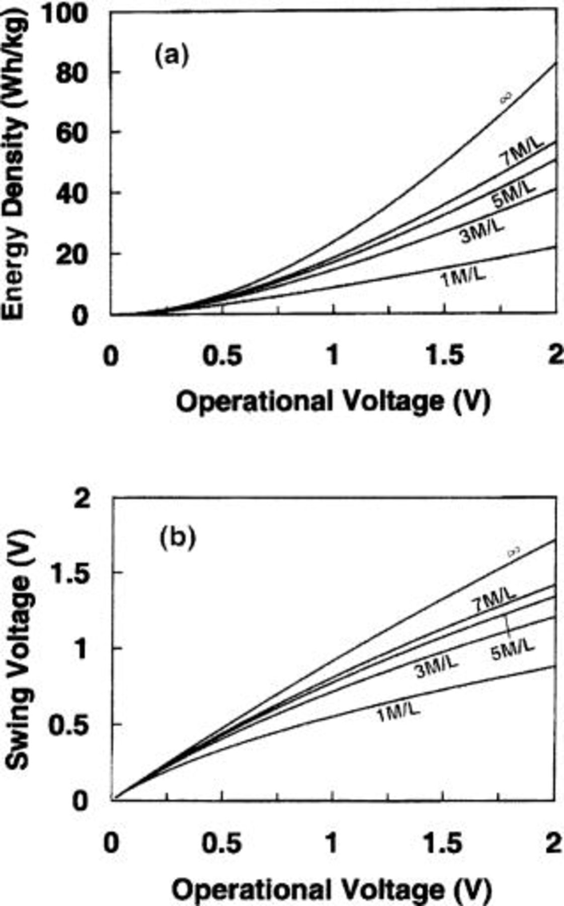
Figure 12. (a) The maximum energy density and (b) swing voltage for aqueous cells as function of the maximum operational voltage.
Open-Circuit Potential (OCP) of Capacitor Electrode
From the dependence of the operational voltage on the maximum energy density of the asymmetric cells, it can be seen that when the asymmetric cell is in the charged state, the potential difference between the anode and cathode electrodes should be as large as possible in order to obtain the maximized energy density. However, the potentials of both electrodes must be within the electrochemical stability window. The OCPs will be important in determining the maximum energy density and the stability of the cells. For the battery electrode, the potential remains almost constant during the charge and discharge cycle. A good electrode material for asymmetric cells should have the potential in the electrolyte to be close to the limit of the electrochemical stability window. For example, the potentials of  and
and  are close to the low limit of the electrochemical stability window, and
  is close to the high limit of the electrochemical stability window. Figure 13 illustrates the potential changes of electrodes during the charge process for three asymmetric cells which have capacitor electrodes with difference OCPs. For the optimal case, the OCP of the capacitor electrode is at B as shown in Fig. 13. When the cell is fully charged, the potential of the capacitor electrode will be at the maximum value, which is close to the upper limit of the electrochemical stability window. The potential difference of the two electrodes is
  The maximum energy density of the cell can be obtained from Eq. 6 or 12. If the OCP is at A as shown in Fig. 13, which is lower than the potential of B, when the cell is fully charged, and the potential difference of two electrodes is less than
  Therefore, the energy density of the cell will be less than the previous case. Contrary to the previous case, if the OCP is at C as shown in Fig. 13, which is higher than the potential of B, it can be seen that in the middle stage of the charge process, the potential of the capacitor electrode will exceed the electrochemical stability window. The continuous charge after
  point as shown in Fig. 13 will cause gas evolution in the cell,16 which will cause some negative effects to the cell including the increase of internal resistance, reducing energy efficiency and cycle life.

Figure 13. Schematic potential charges of electrodes in three asymmetric cells. The OCP of the capacitor electrode is different.
Conclusion
The gravimetric (or volumetric) energy density and voltage swing during charge and discharge cycles for asymmetric cells are found to be dependent on the mass (or volume) ratio of battery electrode, dl capacitor electrode, and electrolyte. The theoretical maximum energy density can be obtained at a mass (or volume) ratio when the capacity of the battery electrode is greater than that of the capacitor electrode. For asymmetric cells with lithium intercalation compound and AC electrodes, the maximum energy density is mainly determined by the ion concentration of the electrolyte. An energy density of about 32 Wh/kg (or 55 Wh/L) is obtained from the asymmetric cell using electrolytes with an ion concentration of 1 M/L. For asymmetric cells with AC and  electrodes, the maximum energy density is mainly determined by the specific capacitance of the carbon electrode. An energy density of about 41 Wh/kg (or 77 Wh/L) is obtained from the asymmetric cell using AC with a specific capacitance of 200 F/g. From an investigation of the dependency of the energy density on the ion concentration, specific capacity of the battery electrode, specific capacitance of the capacitor electrode, and the maximum operational voltage, it is found that the most effective way for increasing energy density for a nonaqueous cell is by using electrolyte with a high ion concentration and a wide electrochemical stable window (with the high operational voltage). However, for an aqueous cell, the high specific capacitance and wide electrochemical stability window are required for obtaining high energy density. The OCP of the capacitor electrode will play an important role in determining the maximum energy density and stability of the asymmetric cell.
This work was partially supported by grant from the NASA-FAR Program under Grant no. NAG5-9420.
Florida State University assisted in meeting the publication costs of this article.